


g
g
g
g
S
INSTRUCTION MANUAL
Model EXP-14
Broadband Tribander 10, 15,
20 Meter
Hy-
Hy-
Hy-
308 Industrial Park
tarkville, MS 39759 USA
323-9538 FAX: (662) 323-6351
ain
ain
ainHy-
ain
Ph: (662)

Table of Contents
Table of Contents
Table of Conten tsTable of Conten ts
Page CHAPTER
1............. ...... .. ... ...... ………….. …. ..... ..... .. ...... ... ...... .. ... ...... .. ...... .. ... ...... .. ..... .... ..... ... .. ...... ... ........... .. .... .... 1-1
General Description... ..... ...... …..... ...... ..... ...... ..... ...... ..... ...... ..... ..... ...... ..... ......... ..... ..... . ...... .......... . ... ... .1 - 1
Driven Element Description….…………………………………………………………………..1-1
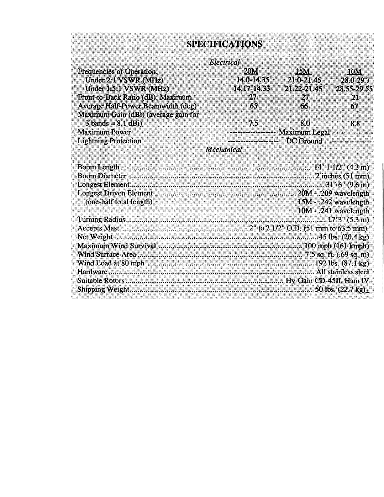
Specifications .....................................................................................….................:................................ 1-2
CHAPTER 2......: ..... ..... .:.... ...... ..... ...... ..... ...... ..... ...... .:... ..... ...... ..... ...... ..... .... ....... ...... ..... ........... ... ... ..... ... .2 -1
Preparation for Asse mbly ...... ..... ...... ..... ...... ..... ...... .. ......... ..... ..... ...... .…. ......... ..... ...... ..... ...... ........... .. ..2- 1
Option QK-710........ .... ....... ..... ..... ...... ..... ...... ..... ...... ..... ...... ..... ...... ........ …. ....... ..... ...... ..... .............. .... ...2 -1
Assembly of the Boom-to-Mast Br acke ts and Boom..... ...... ..... ..…. .....… .. ......... ........ ...... ..... ...... ... ....2-2
Element-to-B oom Brac kets.... ...... ..... ...... ..... ..... ...... ..... ...... ..... .... …....... .... …. ......... ..... ...... ..... ...... .........2- 2
Installation of Tubing Clamps .. ...... ..... ..... -..... ..... ...... ..- ..-....... .... ...... ...... .... ….. .......... ...... ..... ........... . ...2 -4
Element Assembly ... .... ....... ..... ...... ..... ..... ...... ...... ........ ..... ..... ...- -. -. ............. .... ….. .......... ...... ....... ......... ..2 -5
10-15-20 Me te r Dir ec tor E le me n t.... ... .. ... ... ... .. .. .... ... .. ... ... .. ... ... …. .... ... ... .. ... ... . … . . ........ ... .. ... ... ... .. ...... .2- 6
Front Sleeve Element...............................................................….........................…...............................2 -7
Center Driven El emen t..... ...... ..... ..... ...... ..... ...... ..... ...... ..... .... …. ......... ..... .:.... ..... ...…. ....... ...... ........... .. ..2 -8
Rear Sleeve El eme nt.... ....... ...... ..... ...... ..... ..... ...... .... ....... .… .. .......... ...... ..... ...... ..... .... …. ......... ................ .2 -7
10-Meter R efl e c tor Ele me n t.. ... .. ... ... ... .. ... ... ... .. ... ... .. ... ... ... . …. . ........ .. ... ... .. . ..... ... .. ... ... … . . ...... ... .. ...........2- 9
15-20 Meter R eflec tor Ele men t..... ...... ...... ..... ..... ...... ..... ...... ..... ...... ..... ...... ..... ...... ..... .... ……. .............. 2-10
Element Alig nment... ..... ...... ..... ...... ..... ...... ..... ...... ..... ..... --. .......... ..-. ....... ..... ...... ..... ...... ..... ...…............. 2-10
Final Assembly Para-Sleeve Driven Element System ............................................................……..... 2-13
Beta Match Assembly... ....... ..... ...... ..... ...... ..... ...... ..... ..... ...... ..... ...... ..... ........ ...... ..... ...... ..... ........... .... 2 -1 3
Para-Sleeve S pa c er Asse mbl y .. ... .. ... ... ... .. ... ... ... .. ... ... .. ... ... ... .. ... ... ... .. ... ... ... .. ... ... .. ... ... ... .. ... ... ... ..... ... 2 -1 3
Final Assembly Rope Dampening................................................................................................... 2-15
Final Assembly Chec kli st...... ..... ...... ..... ...... ..... .... ....... ...... ..... ..... ...... ..... ...... ..... ...... ..... ...... ........ ... .. .. 2 - 1 5
CHAPTER 3..................................................--..................................................................................... ..... 3- 1
Installation........ ... ..... ... ...... .. ... ..... ... ...... .. ... ...... .. .... .... ...... ... .. ...... ... ..... ... ... ..... ... ..... ... ........... ... ..... ... .. ...... 3- 1
Installation on a Crank- Up Towe r....... ..... ...... .... ....... ..... ..... ......... ..... ...... ... ....... ...... ..... ...... ..... ........... 3- 1
Attaching the Antenna to the Ma st ....... ..... ..... ...... ..... ......... ..... ..... ...... ..... ...... ..... ...... ..... ...... ........... .. .3- 1
Other Types of Towers.... ...... ..... ...... ..... ...... ........ ..... ...... ..... ...... ..... ..... ...... ..... ...... ..... ...... ..... .............. ..3- 1
Lightning Protection.............................................................................................................................3-1
Attachment of Feedli ne ....... ...... ..... ...... ..... ..... .... ....... ...... ..... ...... ..... ...... ...... ....... ...... ..... ...... ........... ..... 3- 2
VSWR Curves.... ...... ..... ...... ..... ...... ..... ...... ..... ..... ...... ..... ...... .... ....... ..... ...... .... ....... ..... ...... .......... ... ... ..... . 3-2
CHAPTER
4............. ... ..... ... ... ..… …. ..... ...... .. ... ..... ... ...... .. ... .... .... ... ...... .. ... ..... ... ...... .. ... .... .... ... ..... ........... ...... .. 4- 1
Operation………... ...... .. ... .... .... . ....... ... ...... .. ... ...... .. ...... .. ... ...... .. ... ...... .. ...... .. ... ...... .. ... ...... .. ...... ... .4- 1
Maintenance .............................……............................................................................................4-1
CHAPTER 5....... ... .. ... .. .... .. ... .. …………... ... ...... .. .. .. .. ... ... ... .. ... ... . .. ... ... .. ...... . .. ..- 5 - 1
Troubleshooting .......... ... ... .. ... ... ... .. ...... .. ... ... . .... .. .... ... .. ... ... ... .. ... ... .. ...... ... .. .. .... ... .. ... ... .. ..5-1
CHAPTER 6....... ..... ..... ...... ...... ..... ...... ..... ...... ..... ...... ..... ..... ...... ..... ...... ..... .... ....... ...... ..... .............. ... ...6 - 1
Service Inform ation ...... .. .... ...... ..... ...... ..... -..- ...- -. .......... ...... ........ ...... ..... ..... ...... ..... ...... ........... ..... ... 6- 1
Parts List.............………….................................................................................................................6-1
Converting America n Mea sureme nts to Metr ic..... ..... ...... ..... ...... ..... ..... .... ....... ...... ..... ...... ..... ...... ...6 -3
-i-

LIST OF ILLUSTRATIONS
Figure
e
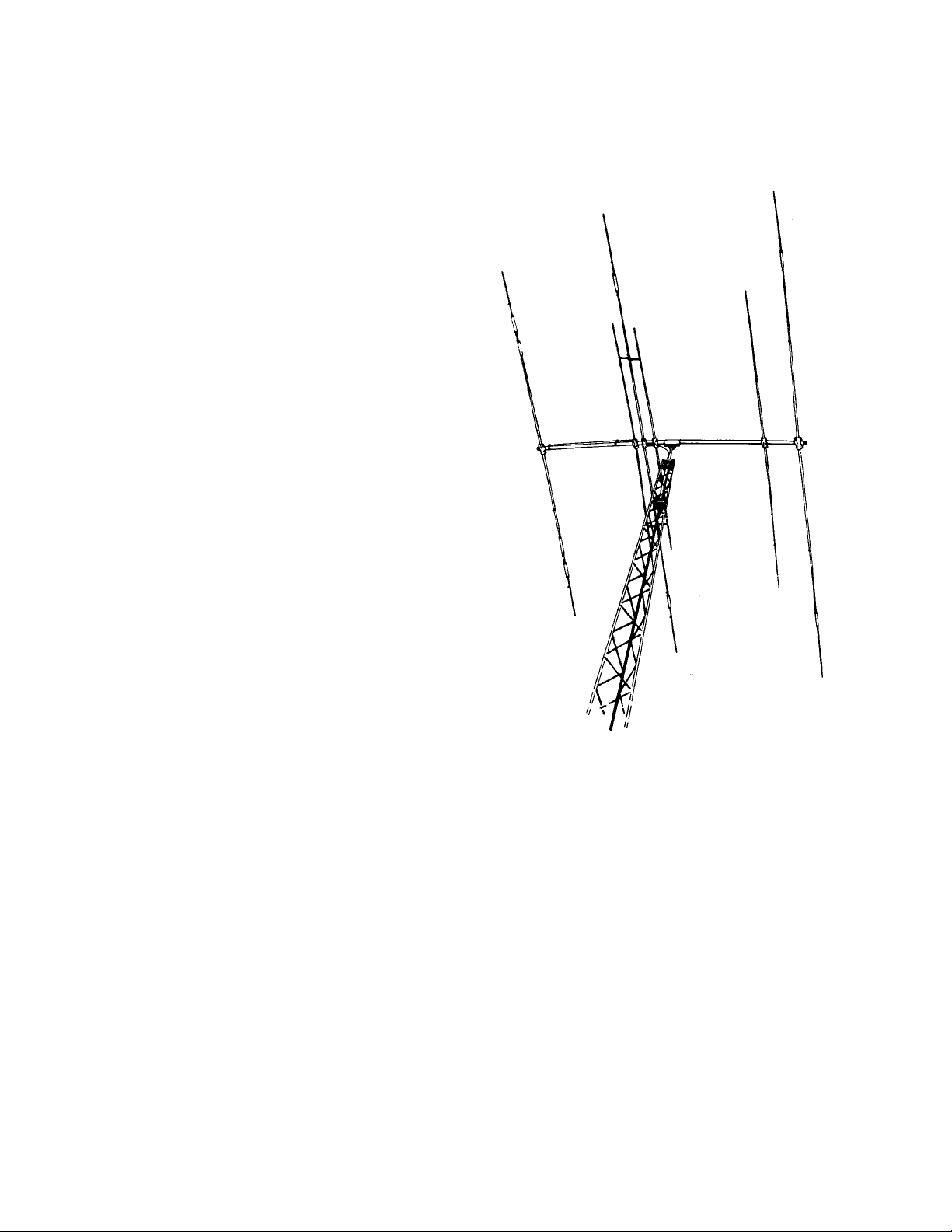
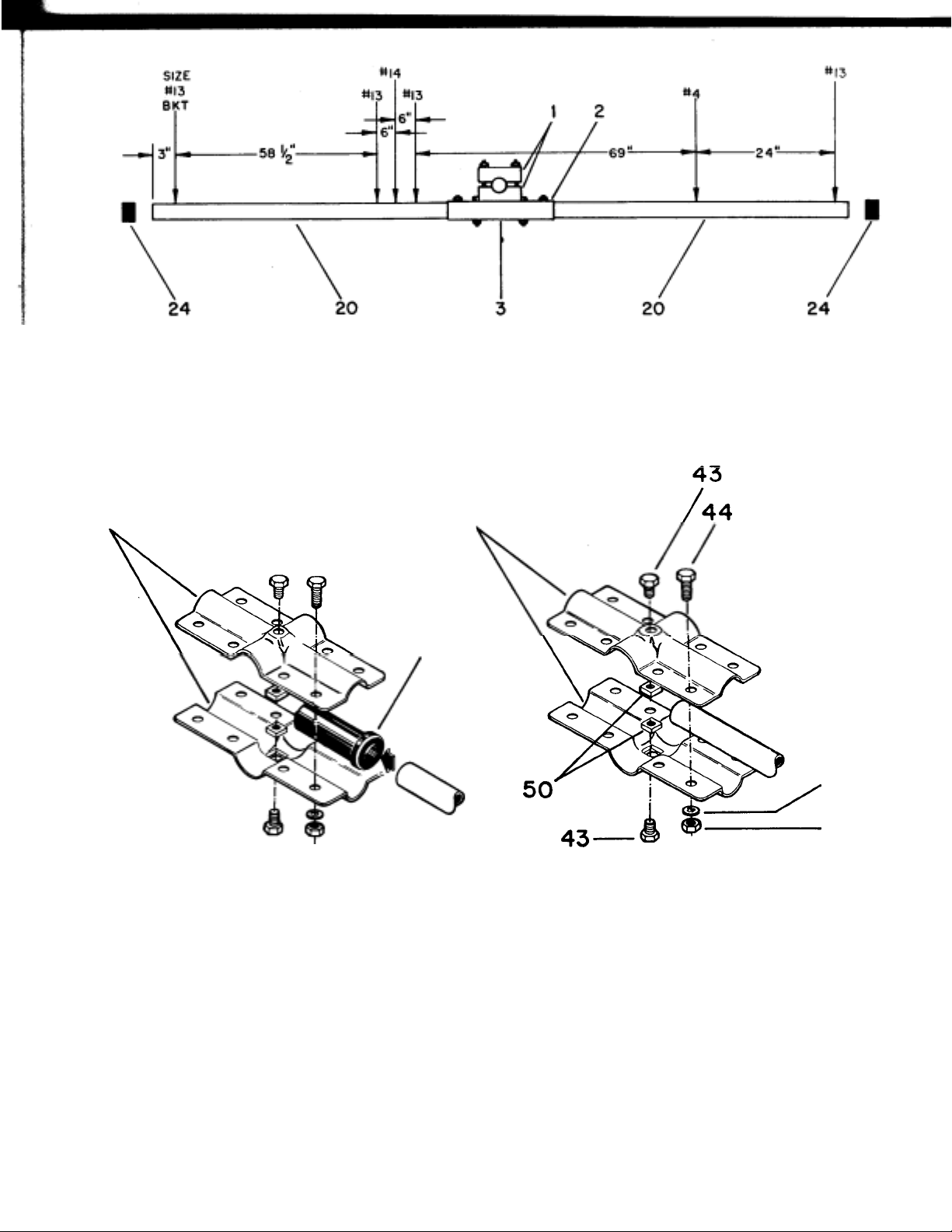
1 Overall View ................. ... ... ... ....... ... ... ... ....... ... ... ...... .... ... ... ...... .... ... ... ....... ... ... ...... .... .......1-1
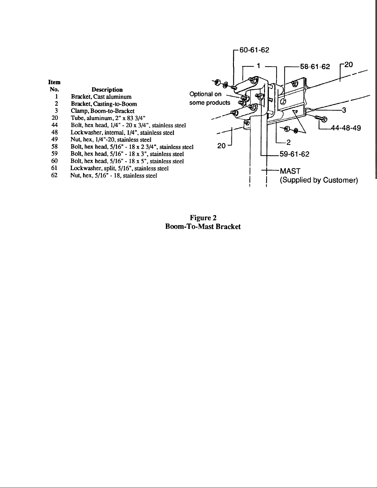
2 Boom-to-Mast Bracket....... ...... .... ... ...... .... ... ...... ... .... ...... ... ... .... ...... ... ... ....... ... ... ....... ... ...2 -2
3 Assembly of Boom .......... ... ....... ... ... ... ....... ... ... ....... ... ... ... ....... ... ... ... ....... ... ... ....... ... ... ... ....2-3
4 Element-to-Boom Brackets ........ ... .... ...... ... ... ....... ... ... ... ....... ... ... ....... ... ... ....... ... ... ... ....... 2-3
5 Tubing Clamps .......... ... .... ... ...... .... ... ... ...... .... .... .. ...... .... ... ... ...... .... ... ...... .... ... ... ...... .... ... ....2-4
6 10-15-20 Meter Director Element........ .... ... ...... .... ... ...... ... .... ...... ... ... ....... .... .. ....... ... ... ..2-6
7 Front Sleeve Element............ ...... ... .... ...... ... .... ...... ..... . ....... ... ... ... ....... ... ... ....... ... ... ....... ... 2-7
8 Rear Sleeve Element ............. ... ....... ... ... ....... ... ... ... ....... ... ... ...... .... ... ...... ... .... ... ...... .... ... ...2 -7
9 Center Driven Element ............ ... ...... .... ... ...... ... .... ..... .... ... .... ...... ... .... ...... ... ... .... ...... ... ... .2-8
10 10 Meter Reflector Element ............... .... ... ...... .... ... ...... ... ... ....... ... ... ....... ... ... ....... ... ... ....2-9
11 15-20 Meter Reflector Element......... ...... .... ... ...... ... ....... ..... . ....... ... ... ....... ... ... ...... .... ~ 2-10
12 Element Assembly and Antenna Dim e nsions ... ... ... ....... ... ... ....... ... ... ...... .... ... ...... ... . 2-11
13 Para-Sleeve Driven Element Connection s.. ... ....... ... ... ....... ... ... ....... ... ...... ... .... ...... ... 2-12
Pag
Detail A Beta Support Clamps and Insulator Assembl y ...... .... ...... ... ... ....... ... ...... .... .. 2-12
Detail B Beta Shorting Clamp Assembly ....... ... ... .... ...... ..... .. ...... ... ... ....... ... ... ....... ... ... ... 2-12
14 Para-Sleeve Spacer Detail....... ...... ... ... ....... ... .... ...... ... ... ....... ... ... ...... .. 2-14
Detail A 5/8" Clamp on Open-Sleeve Spa cer Insu lator.. ...... ... ... ....... ... ... ....... ... ...... ... .... . 2-14
Detail B 11/4" Clamp on Open-Sleeve Spacer I nsulator. ... ....... ... ... ....... ... ... ...... ..... .... 2-14
15 Rope Dampening .......... .... ...... ... ... ....... ... ... ... ........ .. ... ....... ... ... ... ....... ... ... ........ .. ... ... ...... 2-15
16 VSWR Charts ............... ..... .... ... ... ...... .... ... ... ...... ..... .. ...... ... .... ... ...... .... ... ... ....... ... ... ...... .....3-
2 Attachment
1 VSWR Record................. ... .... ... ...... ... .... ...... ... .... .... ..... ... .... ...... ... ... .... ...... ... .... ...... ..... .6 -4
Insert Element Assembly and Antenna Dimensions
CHAPTER 1
General Description
The Hy-Gain Explorer 14 is a very unique 4-element, three band beam antenna designed for
broadband, high performance, high efficiency
operation on the Amateur 10, 15, and 20 meter
bands. The boom length of 14 feet 11/2 inches
(4.17 m) and a longest element of 31 feet 6 inches
(9.6 m) combine for a modest 17 foot 3 inch
turning radius, small enough for most city lots.
Broadbanding is accomplished through the use of
a monoband reflector on 10 meters, a duoband
reflector on 15 and 20 meters and a very unique
driven element system called the Para-Sleeve
Stainless steel hardware and clamps are used on
all electrical and mechanical connections. HyGain's 50 ohm BN-86 balun and new Beta MultiMatch are supplied. Add-on kits for a 30 or 40
meter driven element are available as option QK-
710. The antenna is designed to fit masts from 2"
to 2 1/2" in diameter and can be rotated with Hy-
'
-
-
-
-
Driven Element
The Explorer 14 utilizes a new concept in driven
element design, called the Para-Sleeve System
(Patent No. 4,604,628). Basically, the design consists of on *open-sleeve dipole that has been optimized for maximum bandwidth and directivity
within a Yagi-Uda configuration of parasitic elements. The open-sleeve dipole has evolved from
the coaxial sleeve dipole; however, it is much
easier to tune and exhibits less wind loading. The
ParaSleeve System consist of a trapped driven
element for 15 and 20 meters, electrically
connected to the balun and Beta-Match; and a set
This driven element system allows half element
lengths of 0.209 wavelength on 20 meters, 0.242
wavelengths on 15 meters and 0.241 wavelength on
of two parallel sleeve element for 10 meters.
For more information on the open-sleeve dipole, see H.E. King and
*
J.L.
of a Balun-Fed Open-Sleeve Dipole in Front of a Metallic Reflector", IEEE Trans. Antennas Propagation,
Vol. AP-20,201-204,
March
1972. Also
see: Roger
Cox,
"The Open-Sleeve Antenna", CQ Magazine,
Figure 1
Wong, "An Experimental Study
Vol. 39,
CHAPTER 6
p
361/
.
Preparation For Assembly
FOR OUR OVERSEAS CUSTOMERS: If you
use the Metric System, see American-to-Metric Conversion Table in the rear of this
manual. The United States uses American
units of weights and measures.
Choose a large, clear area to assemble the
EX14. The area must be at least 14' x 32' (4.3
m x 9.7 m). You may wish to use sawhorses or
chairs to support the boom during assembly.
An alternate method involves driving a 5' (1.5
m) leng th of mas t ma te ri al in t o th e gr ound
and attaching the boom and boom-to-mast
bracket to this mast temporarily during
assembly. This permits eye level installation
of parts and allows easy alignment of
elements after assembly. If you assemble this
antenna over a grassy area, precautions
should be taken so that hardware is not
accidentally lost during assembly. A concrete
The assembly of this antenna will be easier if
you read this manual completely through at
least three (3) times before beginning
assembly. Allow at least 5 hours for assembly.
Double and tri
NOTE: An
in this manual for use when assembling the
Option QK-710
The Hy-Gain Model QK-710 is an optional kit
that will allow you to add 30 or 40 meter
operation to your Explorer 14 antenna. The
kit supplies all the necessary hardware and
instructions to add an extension onto the
Para-Sleeve driven element for either 30 or 40
If you anticipate adding this kit to your
Explorer 14, you may make the following
adjustments before adding the QK 710.
le check ALL dimensions
extra Figure 12 has been inserted
Whenunpackingyou antenna, check inside of
all tubing parts (traps, smaller tubing, etc.).
To conserve space, these smaller articles are
sometimes put inside larger pieces. Check all
parts against the Parts List to make sure no
parts are missing. The hardware supplied
with this antenna is bagged by thread size for
All tubing supplied with the EX-14 telescopes
together. Make all measurements to the given
dimensions, plus or minus, no more than 1/8
- Disassemble the Para-Sleeve spacers from
the sleeve elements (FS-1 and RS-1).
Figure 14.
Increase the distance between the central
driven element and both sleeve elements
from 6" to 7" . This wil l redu ce th e
distance to the director and 10 meter
reflector by 1" each. See Figure 12.
Increase the length of the DE-2 from
2" to 37 1/2"
Slide the 15 meter DE trap all the way
Adjust FS-2 to 48" and RS-2 to
Remove DE-3 and the 1/2" element
tubing clamps from the center driven
element. Save the compression clamps.
An extension to the spacers
-
See
Assembly of the Boom-to-mast Brack-
tighten the bolts unt
ucted to do so.
g
Select the boom-to-bracket clamp parts (Item
Nos. 2 and 3). Loosely assemble them on the
boom ends (Item No. 20), as shown in Figure 2.
Line up the holes on both brackets and both
boom ends. Secure the two brackets together
with four (4) 1/4"-20 x 3/4" bolts, lockwashers
and nuts. Secure the brackets to the boom ends
using the 5/16"-18 x 2 3/4" bolts, lockwashers
and nuts. Tighten these six (6) bolts securely.
Assemble the two cast aluminum brackets (Items
No. 1) on the mast at the desired height above
your tower. Secure the two brackets together
using the two (2) 5/16"-18 x 3" bolts,
lockwashers and nuts. You may wish to drill a
hole through your mast so that a 5/16"-18 x 3
1/2" bolt may be inserted through the cast
brackets and the mast and tightened. This bolt
will prevent the antenna from twisting on the
mast in high winds. See Figure 2. The four (4) 5inch bolts will be installed when the antenna is
installed on the mast.
-
-
To save time, loosely assemble all of the
elementto-boom brackets and their appropriate
hardware before beginning further installation of
the antenna. See Figure 4. The different size
brackets can be identified by a number stamped
into the surface of each bracket half DO NOT
il instr
NOTE: Bracket size #14 is used on the center
driven element. Bracket size #13 is used on the
driven element sleeves and on the director and
15/20 reflector. Each size number is stamped into
At this time, slide each el ement-to-boom bracket
over a boom end and position all of the brackets
close to their final attachment points. See Fi gure
3 and Fi
Hand-tighten the hardware on each element-toboom bracket to prevent losing small parts, and
to prevent bracket movement on the boom.
-
ure 12.
Ite Item
No. Description No. Description
1 Bracket, Cast Aluminum 20
2 Bracket, Casting-to-Boom 24 Caplug, 2", black
3 Clamp, Boom-to-Bracket
Tube, aluminum, 2"x 83
Figure 3 Assembly
of Boom
Driven/Sleeve Detail
NOTE: The #4, # 13 and # 14 brackets use the same size
bolts, lockwashers and nuts - in identical locations.
Item Item
No. Description No. Description
4 Bracket, Element-to-Boom, #4 43
5 Bracket, Element-to-Boom, #13 44
6 Bracket, Element-to-Boom, #14 48 Lockwasher, internal, 1/4", stainless steel
25 Insulator, Front & Rear Sleeves, 5/8" I.D. 49 Nut, hex, 1/4"-20, stainless steel
28 Insulator, Driven Element, 11/4" I.D. 50 Nut, square, 1/4"-20, stainless steel
Bolt, hex head, 1/4"-20 x 3/8", stainless
Bolt, hex head, 1/4"-20 x 3/4", stainless
Figure 4
Element -T o- Boo m B ra ck ets
-
48
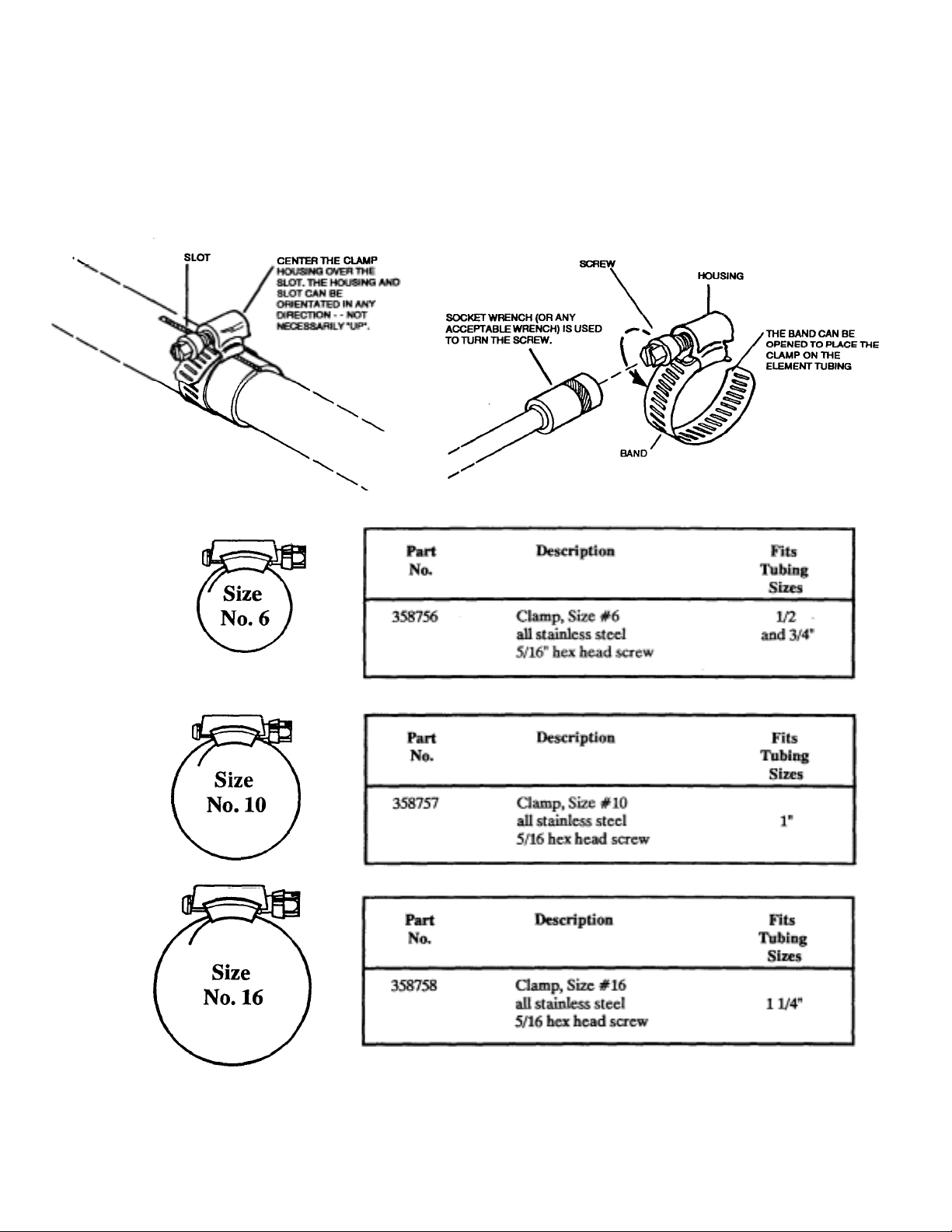
Installation of Tubing Clamps
Select the proper size tubing clamp as shown
in the chart. When installing the clamps, place
the clamp near the tube end with the top of the
clamp over the slot in the tube as shown in
Figure 5.
After adjustment of the tubing length, tighten
the clamp with a 5/16 inch nut driver, socket,
or open end wrench until the tubing will not
-
-
-

Element Assembl
y
Because of the broadband nature of the EX 14, it is supplied with only one setting for use
on all modes on all of the 20, 15, and 10 meter
bands. If assembled and installed correctly,
the VSWR should be below 2:1 on any
frequency on these bands.
The following steps will be in singular form.
Do each element assembly step, first for one
side of the boom and then for the other side.
The dimensions shown in Figure 12 are in
American units on the right side and Metric on
the left side.
The elements may be assembled indoors, perhaps in the garage or basement work area,
especially if the weather is cold, wet or windy
outside. Take your time, and recheck all
element dimensions. The elements should be
attached to the boom outside, at a location
near your tower.
After each element is assembled to the boom,
tighten the eight (8) 1/4"-20 x 3/4" bolts. After
all elements are assembled, make sure that
they all lie in a horizontal plane at 90 degrees
to the mast, then securely tighten the two (2)
anchor bolts on each element.

-
y
-
Item
Assemble the 10-15-20 meter director as
No. Description
shown in Figure 6 and 12. Use trap part
numbers 878749 and 878694 and install with
the tubing slots and trap drain holes facing
16 Tube, aluminum, 11/4" x 48", D1
17 Tube, aluminum, 11/8" x 30", swaged, D2
the ground and the labeled trap ends toward
the boom. Use Figure 6 and Detail "A" as
guides. Tighten all element tubing clamps
Detail A Trap Detail -
NOTE: Make sure that all trap caps are
firml
seated while measuring dimensions.
Figure 6 10-15-20 Meter

Select the FS-1 section (5/8" x 48") and a small
y
driven element insulator (Item No. 25). Slip the
insulator on the unslotted end of the FS-1 section, completely.
Install a #6 tubing clamp on the slotted end of
the FS-1 section and in sert one end of the FS-2
section (7/16" x 53") to the dimension shown in
Figure 7. Tighten the tubing clamp securely
Figure 7
Item
No.
13
14
22
25
AO-3955-B-
Description
Tube, al umi nu m, 5/ 8" x 48", swa ged, RS- 1, F S1 Tube, aluminum, 7/16" x 53"
Caplug , 7/ 16" , bl ac k
Front Sleeve Element
Rear Sleeve Element
Select the RS-1 section (5/8" x 48") and a
small driven element insulator (Item No. 25).
Slip the insulator on the unslotted end of the
RS-1 section, completely.
Assemble the remainder of the Rear Sleeve
Element using a #6 tubing clamp and the RS-2
section (7/16" x 53"). Set it to the dimension
shown in Figure 8. Tighten the tubing clamp
securel
and recheck the RS-2 dimension.
Item
No.
13
14
22
25
Description
Tube, al umi nu m, 5/ 8" x 48", swa ged, RS- 1, F S1 Tube, aluminum, 7/16" x 53"
Caplug , 7/ 16" , bl ac k
Figure 8 Rear Sleeve
-

TUBING CLAMP
p
easu
t
SIZE N0. 16 SIZE N0. 10
-
-
-
N
Select the DE-1 section (11/4" x 83") and a
Item
No. Description
large driven element insulator (see Figure 4).
Slip the insulator on the unslotted end of the
DE-1 section, com
letely.
7 T ube Assembly, aluminum, 11/4" x 83", R1,
DE-1
Install a #16 tubing clamp onto the slotted end
of the DE-1 and insert the unslotted end of the
DE-2 (1 1/8" x 42") to the dimension shown
in Figure 9. Tighten the tubing clamp securely
and recheck the DE-2 dimension.
Assemble the remainder of the center driven
element in the same manner using dimensions
NOTE: ON ALL TRAPS MAKE SURE ALL DRAIN
HOLES ARE FACING THE GROUND, ALL L ABELED
ENDS ARE TOWARDS THE BOOM AND ALL
INSULATORS AND TRAP CAPS ARE FIRMLY
SEATED. ALSO ON ALL TUBING ATTACHED TO
TRAPS, MAKE SURE ALL SLOTS ARE FACING THE
GROUND AND THE SMALL DRAIN HOLES ARE
ALIGNED WITH THE SLOTS.
Detail A Trap Detail -
M
ring Poin
from Figure 9. Use 15 meter trap Part Number

---
-
Assemble the 10-meter reflector as shown in
Figure 10, using #6 tubing clamps. Tighten all
element tubing clamps with the slots facing
the ground and recheck all dimensions.
Figure 10 10 Meter
Reflector Element
Item
No. Description
10 Tube, aluminum, 7/8" x 55", swaged, R21
11 Tube, aluminum, 5/8"x 26", swaged, R22
12 Tube, aluminum, 7/16" x 42 3/4", R2-3
22 Caplug, 7/16", black

N
p
-
Assemble the 15-20 meter reflector, as shown
in Figure 11, using # 16, # 10 and # 6 tubing
clamps. Use trap Part Number 878694 and
install with tubing slots and trap drain holes
facing the ground and the labeled trap end
toward the boom. Use Figure 11 and Detail
"A" as guides. Tighten all element tubing
clam
s and recheck all dimensions.
Element Alignment
Item
No.
7 8
9 22
65
Description
Tube Assembly, aluminum, 11/4" x 83", Rl, DE1 Tube, aluminum, 11/8" x 54", swaged, R2
Tube, aluminum, 7/16" x 37", R3,
DE-3 Caplug, 7/16", black
After
all elements
all elements in the horizontal plane at 90
from the mast. Also, recheck all dimensions
have been installed, align
°
Detail A Trap Detail -
between element centers as shown in Figure
12. Securely tighten each set of eight (8) 1/4 "-
Figure 11 15-20 Meter
20 x 3/4" bolts on every element-to-boom
bracket, then tighten both anchor bolts on
each bracket. See Figure 4. The anchor bolts
should be tightened flush to the al
bracket.
uminum

*NOTE: THESE MEASUREMENTS ARE
LONGER THAN THE MEASUREMENTS
OF THE TUBE ITSELF DUE TO THE
DEPTH OF THE BOOM-TODRIVEN
ELEMENT INSULATORS.

DO NOT INSTALL THE ANCHOR BOLT,
-
-
-

Final Assembly Para-sleeve Driven
Sy
y
eta Matc
ssembly
g
Element
stem
Do not allow the pigtail wires to touch either
the boom or the element-to-boom bracket.
Select the two (2) 1 1/4" aluminum tubing
clamps, four (4) 5/8" aluminum tubing clamps,
two (2) 1/4"-20 x 11/4" bolts, two (2) 1/4"-20
hex nuts, six (6) 1/4" lockwashers, four (4)
#10-24 x 1" bolts, and four (4) # 10-24 hex
nuts. Assemble the two (2) 11/4" tubing clamps
onto the center driven element and the f our (4)
5/8" tubing clamps onto the sleeve elements as
shown in Figure 13. Tighten these clamps
Select the two (2) boom jumper straps, four (4)
# 10 lockwashers and four (4) # 10 hex nuts.
Assemble these straps to the sleeve elements as
shown in Figure 13. The front boom jumper
strap is installed below the boom, and the rear
boom jumper strap is installed above the
boom. DO NOT allow these straps to short out
against the boom. Tighten the hardware
Select the BN-86, 50 ohm balun, U-bolt, four
(4) 7" pigtail wires and associated hardware
and assemble as shown in Figure 13. Tighten
all hardware securely. The balun sh ould slope
down towards the rear end, when i nstalled, so
that water may drain out during rain showers.
Para-sleeve Spacer Assembl
Select the remaining four (4) 1 1/4" aluminum
tubing clamps, four (4) 5/8" aluminum tubing
clamps, four (4) sleeve spacer insulators, four
(4) 1/4"-20 x 1 1/4" bolts, four (4) 1/4"
lockwashers, four (4) 1/4"-20 hex nuts, four (4)
#10-24 x 1" bolts, four (4) #10 lockwashers,
and four (4) #10-24 hex nuts and assemble as
shown in Figure 14. The sleeve spacers should
be installed near the ends of the FS-1 and RS-1
sections. Tighten all bolts securely.
NOTE: If the QK-710 option is used, do not
attach the spacers to the sleeve elements un til
the extension is added.
B
NOTE: The Beta Match Assembly is not used
in the 40-meter conversion of the Explorer 14,
therefore, it need not be assembled if you plan
to add 40-meter operation. Also, the two
pigtail wires going to the Beta Match need n ot
be installed for 40 meters.
Select the two (2) beta match tubes (3/4" x
60"), beta support clamp, beta support
insulator, beta top insulator, and associated
hardware and clamps, as shown in Figure 13
and Details "A" and "B". Assemble as shown
in Figure 13 and Details "A"and "B".
The shorting clamp should be flush with the
ends of the beta match tubes. The opposite
ends of the beta tubes should be even with the
front edge of the center driven element-toboom bracket. Ti
h A
-
hten all hardware securely.
-

---
---
Detail A 5/8" Clamp on
Open-Sleeve Spacer
Insulator
Item
No. Description
7 Tube Assembly, aluminum, 11/4" x 83", R1, DE1
13 Tube, aluminum, swaged, 5/8" x 48", RS-1, FS-1
14 Tube, aluminum, 7/16" x 53", RS-2, FS-2
29 Insulator, Open-Sleeve Spacer
Figure 14 Para-Sleeve
Detail B 11/4" Clamp on
Open-Sleeve Spacer
Insulator
Item
No. Description
45 Bolt, hex head, 1/4"-20 x 11/4", stainless
steel
48 Lockwasher, internal, 1/4", stainless steel
49 Nut, hex, 1/4"-20, stainless steel
Spacer Detail
-

Final Assembly Rope Dampening
)
g
g
Final Assembly Checklist
Select the dampener rope and cut it into two
equal lengths of six feet each. Slip a rope in to
the end of each 10 meter reflector element.
With abou t a 1/2" of rope extending from the
element end, separate the fibers and fold
them back over the element end. Refer to
Figure 15. Now slip a 7/16" caplug over the
element and rope. The rope inside the element
will dampen vibrations caused by low wind
speeds. Place a 7/16" caplug on each end of
the trapped elements. Select the 2" caplugs
and place one on each boom end. Check all
element spacings and dimensions and tighten
all of the bolts before continuing.
-
-
-
1. - Check the distance between elements, 58
1/2", 6", 6", 69" and 24". (Distances
will be 57 1/ 2", 7" , 7" , 68" and 24" if
option QK-710 is used.
2. - Check the exposed element lengths
against the dimensions shown in Figure
12. Check both sides of each element.
Ensure that the trap caps are firmly
seated. (Note differences if option QK-
3. - Check the tightness of each element
tubing clamp. You should not be able to turn
an element that is securely clamped
within a lar
er element.
4. - Check to ensure all elements lie in the
same pl ane and will be perpendicu lar (at
°
5. -Ensure that all trap drain holes and all
tubing slots will b e fa ci ng the g round wh en
Figure 15 Rope
Dampenin
6.-Securely tighten all bolts used in the ele-
-
-
7. -Securely tighten all bolts used in the
-
-

In
stallatio
g
n
Attaching the Antenna to the Mast
IMPORTANT
The Explorer 14 is a moderately large antenna
and requires some consideration as to how you
are going to get it to the top of the tower.
Thoroughly read this section before beginning to
install yo ur an te nna.
Installation on a Crank-Up Tower
Crank the tower down completely or as low as
it will go, and block all sections from moving
by using a 2" x 4" piece of wood or a solid
iron bar for heavier towers. The block should
be inserted through the lattice structure
before the tower is completely down, then the
tower can be cranked down until the block
takes the weight off the winch.
Use a ladder to reach the top of the tower.
NEVER CLIMB THE LATTICE
STRUCTURE OF ANY CRANK-UP
TOWER! Attach the mast to the tower and
rotator. (The cast aluminum boom-to-mast
brackets should be installed on the mast as
shown in Figure 2. See Chapter 2.) Attach a
gin pole to the tower to assist in lifting the
Explorer 14.
Attach the lifting rope to the balance point of
the antenna. Be careful not to damage the
rear sleeve assembly next to the boom-to-mast
clamp. The lifting rope should be fed through
the gin pole or other pulley arrangement attached to the tower. The other end should be
at ground level, available to the ground crew
for lifting. Guide ropes may be loosely looped
over the boom ends and used by the ground
crew to guide the antenna away from the
tower and ladder. Each guide rope's two loose
ends should be held by the ground crew, so
that the guide rope can be retrieved. Always
use a nonconductive type of rope if working
near power lines.
When the antenna reaches the mast bracket,
the four (4) 5" bolts should be inserted
through the holes in the mast brackets and
secured using 5/16"-18 lockwashers and nuts.
Tighten all bolts securely. You may wish to
use a deep well socket set to tighten these
bolts.
Other Types Of Towers
When installing the Explorer 14 on a guyed
tower, you may wish to use a different guide
system. If you have insulators on your guy
wires, y ou will need to keep th e antenna away
from the guy wires as well as the tower. You
may wish to use two ropes attached together
at the top of the tower and attached to the
gound about 15 feet apart. These two ropes
can then be used to slide the antenna on as it
is also being lefted. The two ropes will need to
be far enough from the tower base to allow
some sag and still support the antenna away
from the guy wires.
WARNING
Installation of this product near power
lies is dangerous. For your safety, follow
the instructions.
Lightning Protection
For proper lightning protection, you must
ground your antenna supporting structure.
Grounding will ensure noise-free operation
and low SWR. A proper ground consists of a
1/2" x 8" co pper clad steel groun d rod d riven
into the ground approximately 12" away from
the concrete tower base. Connect the tower to
the ground rod using #8 copper wire and
commercial noncorrosive
round clamps.

Attachment of Feedline
,
Use a good quality 50 ohm coaxial
transmission line such as Times Wire and
Cable RG-213/u or Belden 8214 (foam) or
Belden 8237, 8267 or 9251 (solid). Take extra
care when soldering connectors to foam
dielectric coaxial cable. Weatherproof all
connectors which will be exposed to rain or
ice, with Coax-Seal® or another similar
substance. There is no need to make the
feedline any multiple of wavelengths long.
Attach the transmission line to the BN-86
balun and tighten the connector securely. Tape
the coax to the boom and mast to ensure good
strain relief.
These VSWR curves are typical for this
antenna mounted 70 feet above the ground,
horizontally polarized. Similar curves can be
expected for this antenna mounted between 30
and 100 feet above the ground. DO NOT TRY
TO TUNE THIS ANTENNA FOR LOW
VSWR AT GROUND LEVEL. Higher VSWR
can be expected if mounted at less than 30 feet
or above a roof or large metallic structure.
Forty (40) and eighty (80) meter wire dipoles
should be kept at least 6 feet below this
antenna.
Guy wires should be broken up into
nonresonant lengths (less than 12 foot lengths)
and insulated from the tower if mounted
within 10 feet of the top of the tower.
Coax-Seal(R) is a registered trademark of Universal Electronics
-

Operatio
CHAPTER 4
Connect the other end of your transmission line
to a good quality SWR meter or Thruline@
wattmeter and then to your radio. While using
lower power (less than 200 watts output), check
the VSWR across each band from 14.0 to 29.7
MHz. Record this information for future
reference. See Attachment 1 on the last page of
this manual. Check the VSWR periodically to
ensure proper operation.
The front-to-back ratio may be checked by using
a steady carrier transmitted by a local station (at
least a half mile away). The front-to-back ratio
may be affected by the proximity of metallic
structures or guy wires less than 10 feet below
the antenna.
This completes your installation of the Explorer
14. Happy DX'ing!
Maintenanc
The Explorer 14 antenna is designed to be
relatively maintenance free. All hardware, except
for seven (7) long bolts used in the boom-to-mast
bracket, are made of passivated stainless steel.
The seven (7) long bolts are plated with a thick
layer of cadmium with a protective coating of
clear chromate. The internal tooth-type
lockwashers used in this antenna are made of a
slightly magnetic grade of stainless steel. The
element tubing clamps are made of all stainless
steel. All other metallic parts are aluminum. All
insulators are made of either black polyethylene
or black Cycolac®.
Hy-Gain now recommends genuine Penetrox-A©
from Burndy Corporation for use as an antielectrolytic compound within element
assemblies. This prevents aluminum oxide from
forming on the aluminum surface, thereby
maintaining high electrical conductivity between
element sections, especially in coastal
environments. No other type of conductive paste
should be used. Penetrox-A© may be obtained
from any electrical supply store.
A light amount of clear lacquer or an acrylic
spray may be used to coat the exterior surface of
the element assemblies if heavy oxidation is
likely to occur. Do not use any coating on trap
assemblies. Heavy oxidation of aluminum may
occur if the antenna is installed within 5 miles of
salt water.
When storing this antenna (or if awaiting
installation), care should be taken not to damage
any trap assembly or allow any dirt or insects to
enter any trap assembly. Do not leave the
elements in a grassy area, as wet grass will stain
the aluminum.
Optional
If you use a 1500 watt continuous duty power
amplifier or if you use RTTY at 1500 watts on
this antenna, the BN-86 balun should be replaced
with a suitable high power balun or RF choke.
Hy-Gain makes a new high-power current-type
balun rated at 2000 watts continuous, Model
/BN-4000B for beams.
Thruline® is a registered trademark of Bird Electronics.
Cycolac® is a registered trademark of Borg-Warner.
Pentroz-A® is a registered trademark of Bumdy
-
-

CHAPTER 5
g
y
Troubleshootin
If you encounter problems with the operation
of your Explorer 14, follow these steps to
isolate the cause.
Usually you can isolate problems that occure
in either
our antenna or feedline/feedpoint.
If you experience high VSWR on all bands,
your problem is probably in the feedline or
balun. If you experience high VSWR on some
bands but not all bands, look for problems in
the antenna element lengths or traps or nearby
resonant structures.
-
-

CHAPTER 25
p
g
,
If you are unable to resolve technical
problems, you should contact the Telex/HyGain Customer Service Department in
Minnea
You should fully research your problem by
going through the Troubleshooting Guides in
Chapter 5 before you contact the Customer
Service Department. You should also record
your VSWR across all three bands before
calling.
You should retain your sales receipt or other
proof of purchase for antennas that are still
under warranty. (See separate sheet for Telex
Warranty.)
olis, Minnesota.
All requests, inquiries or warranty claims
Amateur Department Telex
Communications, Inc. 9600 Aldrich
Avenue South Minneapolis, MN 55420
Phone: (612) 884-4051 or (612) 8875528
For orderin
Telex/Hy-Gain
Telex Communications, Inc.
8601 East Cornhusker
Highway P.O. Box 5579
Lincoln, NE 68505-5579
replacement parts

PARTS LIST (continued
)
plug, 7/
(
)
, 5/8",
pp
p
p
p
p
g
p
p
p
(
)
,
,
, sq
,
, 5/
Item
No. Part No. Description
Qty
22 455644 Ca
23
24 455625 Caplug, 2", black............................................................................... 2
25 461057 Insulator
26 465595 Insulator, beta support (bottom) ...................................................1
27 465600 Insulator, beta su
29 470486 Insulator, open-sleeve spacer ....................................................... 4
872222 Parts Pack, 395S, Straps .....................................................................1
30 168695 Clam
31 171329 Clam
32 170483 Stra
33 171077 Stra
34 171131 Sleeve, beta shortin
35 171162 Stra
36 177888 Clamp, beta support ........................................................................1
37 871508 "Pigtail" wire, 7" ................................................................................ 4
878682 Parts Pack, 395S, Clamps...................................................................1
38 358756 Clam
39 358757 Clam
40
41 358758 Clamp, tubing #16, stainless steel................................................. 6
-42 541363 U-bolt, # 10-24 x 2 1/2" x 2 3/4" ......................................................1
16", black .......................................................................12
NOT USED
I.D., front and rear sleeves................................... 4
ort (top) ..........................................................1
, tubing, 11/4 "
, tubing, 5/8............................................................................. 8
, boom jumper.........................................................................2
, boom-to-beta, 2" I.D. ...........................................................1
......................... ... .... ... ... .... ... ... .... ... ... .... ... ... .... l
, beta shorting, 3/8" radius ..................................................... 2
, tubing #6, stainless steel ................................................. 14
, tubinyg #10, stainless steel .............................................10
NOT USED
872224-1 Parts Pack, 395S, 1/4" Hardware....................................................... l
43 500156 Bolt
44 505266 Bolt, 1/4"-20 x 3/4", hex head, stainless steel .............................. 56
45 506518 Bolt, 1/4"-20 x 11/4", hex head, stainless steel ............................. 6
46 504098 Bolt, 1/4"-20 x 11/2", hex head, stainless steel ............................. 2
47 505763 Bolt, 1/4"-20 x 13/4", hex head, stainless steel ............................. 2
48 562961 Lockwasher, internal, 1/4", stainless steel ..................................72
49 554099 Nut
50 551367
872225-1 Parts Pack, 395S, #10 and 5/16" Hardware..................................... l
51 500160 Bolt
52 504069 Bolt, #10-24 x 1", hex head, stainless steel ................................. 10
53 500159 Bolt, # 10-24 x 11/2", hex head, stainless steel ............................ 2
54 500157 Bolt, #10-24 x 2", hex head, stainless steel................................... 2
55 565697 Lockwasher, internal, #10, stainless steel.................................. 28
56 554071 Nut, # 10-24, hex, stainless steel .................................................. 24
57 555792 Nut, #10-24, square, stainless steel............................................... 2
58 506968 Bolt
1/4"-20 x 3/8", hex head, stainless steel ..............................14
hex, 1/4"-20, stainless steel ................................................... 64
Nut
uare, 1/4"-20, sstainless steel ............................................
# 10-24 x 5/8", hex head, stainless steel ............................... 4
16"-18 x 2 3/4", hex head, stainless steel........................... 2
-
14

Item
y
No.
Part No.
500392
Bolt, 5/16"-18 x 3", hex head, stainless steel .................................. 2
Description
59
60 500349 Bolt, 5/16"-18 x 5", hex head, stainless steel .................................4
61 564792 Lockwasher, split, 5/16", stainless steel....................................... 13
62 555747 Nut, 5/16"-18, hex, stainless steel .....................................................9
63 873424 Balun, BN-86 .................................................................................... 1
64 878637 Trap, 15M, driven element................................................................ 2
65 878694 Trap, 15M .........................................................................................4
66 878749 Trap, 10M .........................................................................................2
67 850050 Coax-Seal ©.......................................................................................1
68 691138 Rope, 12 ft., black poly .....................................................................1
Qt
Converting American
Measurements To Metric
Use this scale to identify lengths of bolts,
diameters of tubes, etc. The American inch (1 ")
and foot (1') can be converted to centimeters in
1 inch (1 ") = 2.54 cm
1 foot (1') = 30.48 cm
Example:
42" x 2.54 - 106.7 cm
Coax-Seal® is a registered trademark of Universal Electronics Inc.
-

VSWR RECORD
Attachment
6-


hy-gains
prop
p
g
LIMITED WA RRANTY
by gain
and purchased from an authorized dealer or directly from
defects in material and workmanship for a period of 12 months for rotator products and
24 months for antenna products from date of purchase provided the following terms of
this warranty are satisfied.
The purchaser must retain the dated proof-of-purchase (bill of sale, canceled check,
1.
credit card or money order receipt, etc.) describing the product to establish the validity
of the warr ant y claim and subm it th e o rig i na l o r ma c hi ne re pr o duct io n of su ch pr oofof-
purchase to
to deny warranty without dated proof-of-purchase. Any evidence of alteration, erasure,
or forgery shall be cause to void any and all warranty terms immediately.
2. hygain
owner any defective product under warranty, provided the product is returned postage
prepaid
covering postage and handling.
Under no circumstances is
3.
Warrants to the original owner of this product, if manufactured by
by gain
by gain
agrees to repair or replace at
hygain
to
erty by the use of any
with a personal check, cashiers check, or money order for $8.00
at the time of warranty service.
hygain's
hygain
hygain
liable f or co n se q ue ntial dama ge s t o pe rs o n or
roducts.
hygain
option without charge to the original
to be free from
shall have the discretion
by gain
Out-of-warranty Service:
4.
the unit is shipped prepaid. All repaired units will be shipped COD to the owner. Repair
charges will be added to the COD fee unless other arrangements are made.
This warranty is
5.
6. hygain
without incurring any obligation to install such changes upon any of the products
previously manufactured.
All
7.
reserves the right to make changes or improvements in design or manufacture
hygain
iven in lieu of any other warranty expressed or implied.
products to be serviced in-warranty or out-of-warranty should be
hygain will
Mississippi 3975 9, USA
the problem in detail along with a copy of your dated proof-of-purchase.
This warranty gives you specific rights, and you may also have other rights which vary
8.
from state to state.
repair any out-of-warranty product provided
and must be accompanied by a letter describing
 Loading...