

Page 1

DIR-
73
Discoverer 73 Director
40-Meter Kit for DIS-72
K
Instruction Manual
308 Industrial Park Road
Starkville, MS 39759 U S A
PH: 662-323-9538
FAX: 662-323-6551
Page 2

TABLE OF CONTENTS
y
g
General Description ...............................….............................................................................1-1
CHAPTER 2 - PRE-ASSEMBLY
Preparation for Assembly .....................................................................................................2-1
Discoverer 7-2 Disassembl
CHAPTER 3 - ASSEMBLY
Assembly of the Boom-to-Mast Brackets and Boom.........................................................`..3-1
Element-to-Boom Brackets.....................................................................................................3-1
Assembly of the Driven Element...........................................................................................3-3
Installation of Tubing Clamps ........................................ ........................................................3-5
Assembly of the Reflector Element ................................... ....................................................3-7
Assembly of the Director Element.........................................................................................3-8
Driven Element, Reflector and Director Linear-Loading Wire Assembly.......................... 3-11
Beta Match Assembly.......................................................................................................... 3-14
Lightning Protection............................................................................................................ 3-15
Attachment of Feedline ...................................................................................................... 3-15
Boom Support Assembly...........…....................................................................................... 3-15
Information ............................................................. ............ ....2-1
Page
-
CHAPTER 4 - INSTALLATION
Installation............................................................................................................................ 4-17
Installation on a Crank-Up Tower.......................... .............................................................. 4-17
Attaching the Antenna to the Mast ............ ............................................... ........................... 4-17
Other Types of Towers ......................................... ............................................................... 4-18
Operation ............................................................................................................................. 4-19
Maintenance....................................................................................................................... 4-19
VSWR Calculations .......................................……………………………………………...4-19
CHAPTER 5 - SERVICE
Service Information .............................................. ............................................................... 5-21
Attachment .......................................................................................................................... 5-22
Parts List.............................................................................................................................. 5-23
Convertin
English Measurements to Metric..............…………………………………......5-25
Page 3

LIST OF ILLUSTRATIONS
g
y
g
y
y
g
g
g
y
pp
g
Figure Pa
1 Assembly of Boom Tubes to Casting-to-Boom Br ac k e t
and Boom-to-Bracket Clamp ........................................................................... 3-2
2 Element-to-Boom Brackets .................................................................................. 3-3
3 Assembl
4 Tubin
5 VSWR Charts ....................................................................................................... 3-6
6 Front-to-Back Ratios ............................................................................................ 3-6
7 Assembl
8 Assembl
9 Overall View of Antenna .................................................................................... 3-10
10 Linear-Loadin
11 Attachment of Linear-Loadin
12 Identification of Linear-Loadin
13 Beta Match Assembl
14 Boom Su
15 Attachin
of the Driven Element.......................................................................... 3-4
Clamps...................................................................................................... 3-5
of the Reflector Element ..................................................................... 3-7
of the Director Element........................................................................ 3-9
Wire Assembly.......................................................................... 3-11
Wire Assembly Near Insulator....................... 3-12
Wires (LLW) ................................................. 3-13
......................................................................................... 3-14
ort Assembly.................................................................................... 3-16
Boom-to-Mast Bracket............................................................................ 4-18
Page 4

CHAPTER 1 GENERAL
INFORMATION
General Description
The Hy-Gain Discoverer 7-3 Director Kit
contains all of the necessary parts and instructions
to convert the Hy-Gain Discover 7-2, 2 element,
40 meter beam into a Discoverer 7-3, 3 element,
40 meter beam.
The Discoverer 7-3 features stainless steel
hardware and clamps on all electrical and most
mechanical connections. It also features a dual
wire boom-support system which gives both
lateral and vertical support and stability.
The Discoverer 7-3 incorporates the principles o f
linear-loading which results in lower loss and
greater radiation efficiency than is possible with
loading coils when used in shortened elements.
The Discoverer 7-3 also features a low voltage
feedpoint that eliminates insulator failures and
assures full power capabilities.
WARNING
When installing your system take extreme care
to avoid any accidental contact with power lines
or overhead obstructions. Failure to exercise this
care could result in serious or fatal injury.
Page 5

*Gain and front-to-back figures verified by
computer modeling using the MININEC-3
and NEC computer codes along with actual
measurements on Hy-Gain's antenna range.
Page 6

CHAPTER 2 PRE-ASSEMBLY
y
y
y
p
y
y
y,
INFORMATION
Preparation for Assembl
FOR OUR OVERSEAS CUSTOMERS: The
United States uses American units of
measurement. If you use the Metric System,
see "Converting American Measurements to
Metric" in Chapter 5.
Choose a large clear area to assembly your
antenna. The area must be at least
(11
m
x 14 m).
If you assemble this antenna
36' x 46'
over a grassy area, precautions should be
taken so that hardware is not accidentally lost
during assembly. A concrete driveway is an
excellent area for assembl
.
TOOLS: The following tools are required for
eas
assembly of the Discoverer
7-3.
after assembly. Check the tightness of ALL
hardware after assembl
.
If you have already assembled the Discoverer
2, and are now adding the Discoverer
7
Director Kit, allow
least 2 hours for
at
7-3
assembly. If you are assembling the
Discoverer
from scratch, allow at least 5
7-3
hours for assembly.
Discoverer 7-2 Disassembly
Information
If you are assembling the Discoverer
7-3
from scratch, skip this section and proceed to
Cha
ter
If you are adding the Discoverer
Kit to a previously assembled Discoverer
The Discoverer
"Assembly".
3,
7-3
must be at ground or
7-2
Director
7-2,
rooftop level to work on it. DO NOT try to
modif
it while on your tower.
NOTE: When unpacking your antenna, check
inside of all tubing for parts (smaller tubing,
etc.). To conserve space, these smaller articles
are sometimes put inside larger pieces. Check
all parts against the Parts List and i llustrations
to make sure no parts are missing.
All tubing supplied with the Discoverer
7-3
telescopes together. Make all measurements
to the given dimensions, plus or minus (t), no
more than 1/8 inchi The assembly of this
antenna will be easier if you read this manual
completely through at least twice before
beginning assembly. Double and triple check
ALL dimensions
The following parts may be disassembled a nd
discarded, as they will be replaced by new
parts in the Director Kit. (See Figure 14,
Boom Support Assembly, in the Discoverer
Manual.)
2
The turnbuckles (Item No.
a later assembl
do not discard them.
will be used in
57)
7-
The chain links (Item No. 58) and mast
clamps (Item No. 60) and all hardware should
be saved for the Discoverer
7-3.
Page 7

The casting-to-boom bracket and boom-tobracket clamp (Item Nos. 2 and 3 of Figure 1
in the Discoverer 7-2 manual) with their
hardware should be loosened and the two
5/16"-18 x 2 3/4" bolts (Item No. 25) removed
from this assembly. The center boom sections
(Item No. 51) can then be removed from the
casting-to-boom bracket and boom-to-bracket
clamp (Item Nos. 2 and 3).
The reflector element-to-boom clamp should
be loosened so that the reflector element can
be moved to 12 inches from the boom end
(measured to the center of the element). Position the reflector element and tighten all
hardware while ensuring the element will lie
in the same horizontal plan as before. The
reflector element length will be adjusted in a
later step.
The driven element-to-boom clamp should be
loosened so that the driven element can be
removed from the boom end. The element-toboom clamp and beta match assembl y should
be disassembled and saved for later
reassembly. The length of the driven element
will be adjusted in a later step.
Page 8

CHAPTER 3
y
ASSEMBLY
Assembly of the Boom-to-Mast
Brackets and Boom
Refer to Figure 1 and begin as follows:
Select the casting-to-boom bracket and
boom-to-bracket clamp (Item Nos. 2 and 3)
and loosely assemble them on the three (3)
boom sections (Item Nos. 67 and 70) with
the hardware shown in Figure 1. To easily
accomplish this, slide the 13/4" O.D. boom
insert (Item No. 70) into one of the 2" x 8 1"
boom sections (Item No. 67) and line up the
holes. Assemble these two boom pieces
loosely to the clamp and bracket (Item Nos.
2 and 3) with a single 5/16"-18 x 2 3/4"
bolt, lockwasher and nut (Item Nos. 25, 27
& 26) to keep the hole alignment. Slide the
other 2" x 81" boom section (Item No. 67)
over the boom insert (Item No. 70) and into
the clamp and bracket assembly. Line up
the holes and install the remaining 5/16"-18
x 2 3/4" bolt, lockwasher and nut (Item
Nos. 25, 27 & 26). Tighten all hardware in
the clamp assembly at this time.
Element-to-Boom Brackets
To save time, loosely assemble ALL of the
element-to-boom brackets and their
appropriate hardware before beginning further
installation of the antenna. See Figure 2. The
different sized brackets can be identified by a
number stamped into the surface of each
bracket half. DO NOT tighten the bolts until
instructed to do so.
Slide the large driven element bracket over
the front boom end to the location shown in
Figure 3. You may wish to assemble this
bracket on the boom at this location. The
center of this bracket should be 115/8 inches
in front of the edge of the boom-to-mast
bracket assembly. The remaining two bracket s
should be slid over each boom end and
positioned. The reflector bracket will be 12
inches from the rear boom end and the
director bracket will be 14 inches from the
front boom end. Do not tighten at this time.
Attach the four remaining 2" O.D. boom
sections (Item Nos. 50 and 51) from the
Discoverer 7-2, and secure with the
hardware shown in Figure 1. Tighten all
hardware securel
If the reflector had been preassembled, ensure that the reflector element will be parallel to the ground when installed. If not, then
loosen the anchor screws on the ele ment-toboom bracket and turn the element to its
proper position. Retighten the anchor
screws.
.
Page 9

Figure 1 Assembly of Boom Tu bes to Cast ing-to-
Boom Bracket and Boom-to-Bracket Clamp
Page 10

NOTE: ASSEMBLY HARDWARE FOR THE
y
g
p
DRIVEN ELEMENT BRACKET IS THE
SAME AS USED ON THE REFLECTOR
BRACKET.
DRIVEN ELEMENT DETAIL
Figure 2 Element-to-
Boom Brackets
Assembl
of the Driven Element
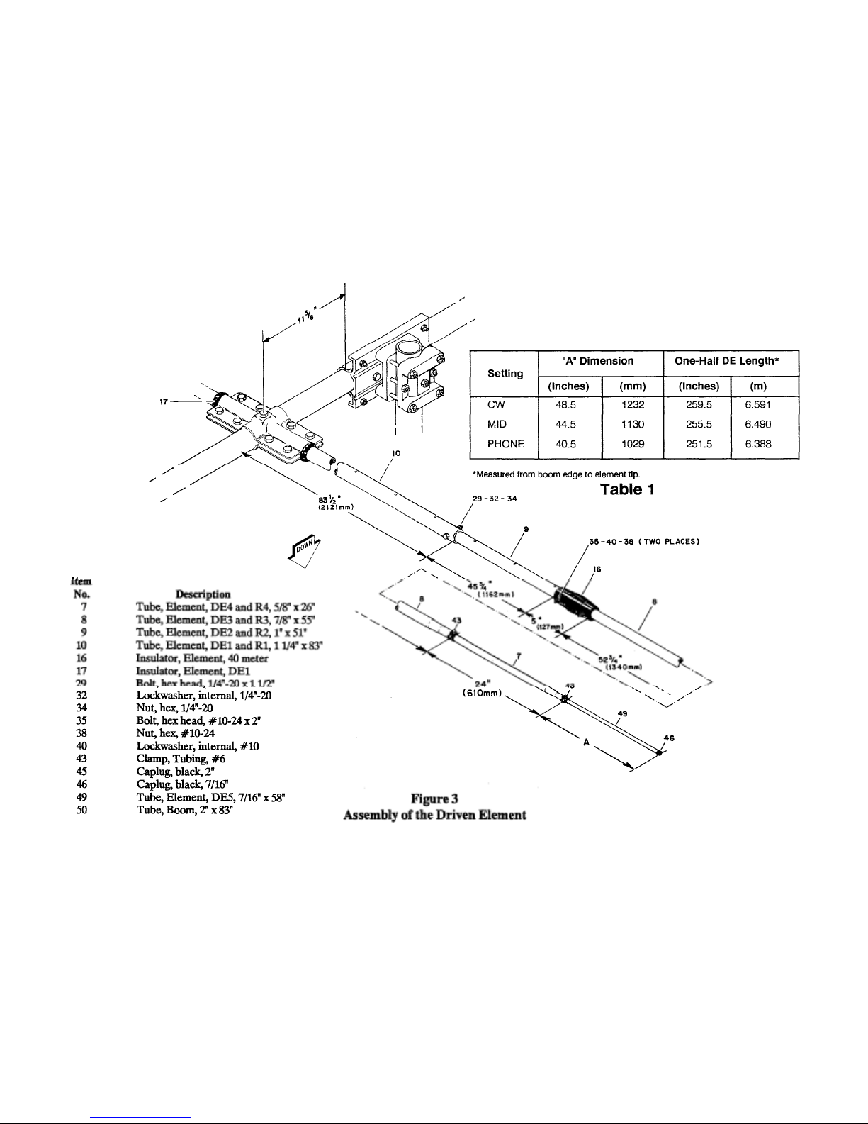
Select the parts as listed in Figure 3 and assemble them as shown in Figure 3. Before
ti
htening the hardware, make sure that:
DE1(Item No. 10) is inserted completely
into the driven element insulator.
DE 1 (Item No. 10) is positioned with the
small holes u
and down.
DIRECTOR/REFLECTOR DETAIL
NOTE: If you are adding the Discoverer 7-3
Director Kit to a preassembled Discoverer 72, then you only need to readjust the DE5
section, "A"dimension, to that shown in Table
1 and position the driven element on the
boom.
Tighten the anchor bolts on the element-toboom bracket (Item No. 28) last. This will ensure that the element will not slip on the
boom.
DE1(Item No. 10) is positioned at 90
degrees from the boom-to-mast bracket to
that the element will be horizontal when
installed on the mast.
Page 11
Page 12
Installation of
p
g
Tubing Clamps
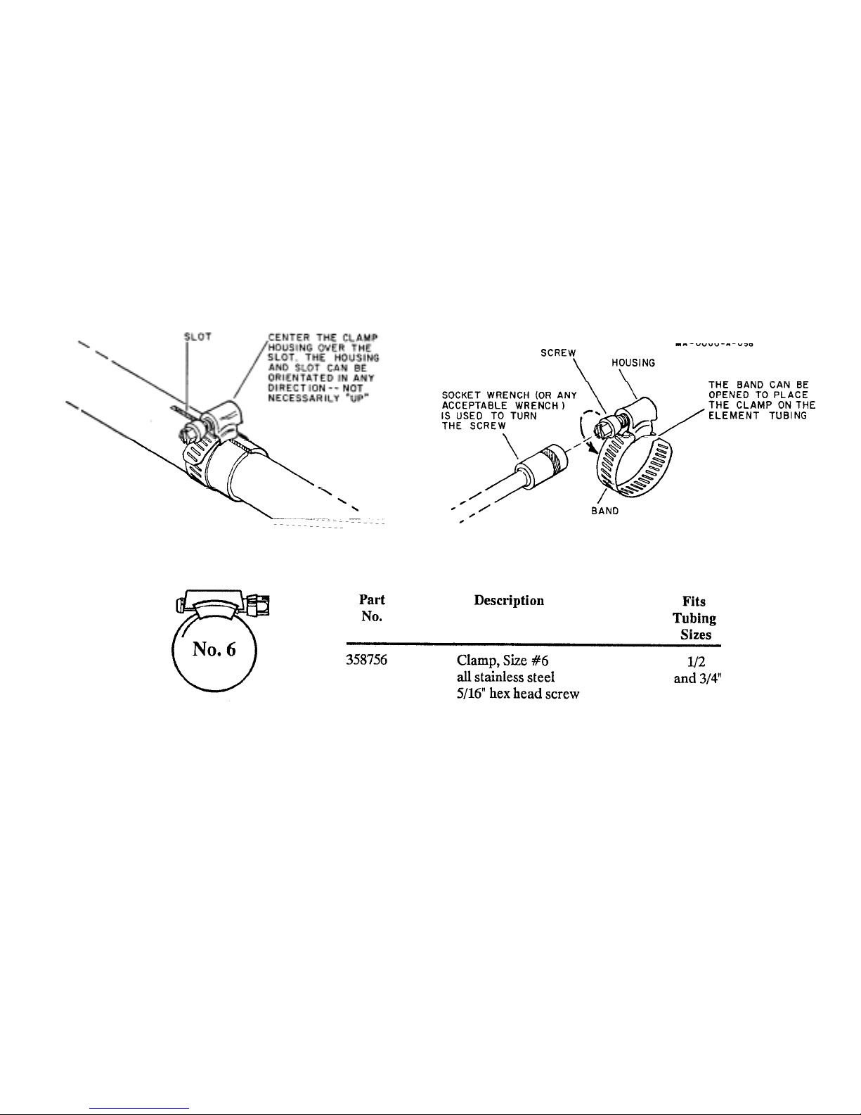
Select the proper size tube clamp as shown in
the chart. When installing the clamps, place
the clamp near the tube end with the top of
the clamp over the slot in the tube as shown
in Figure 4.
After adjustment of the tubing lengths, tighten
the clamp with a 5/16 inch nut driv er, socket,
or open end wrench until the tubing will not
twist or telesco
e.
Tighten these clamps securely after setting
Item Number 7 and 49 to their proper length.
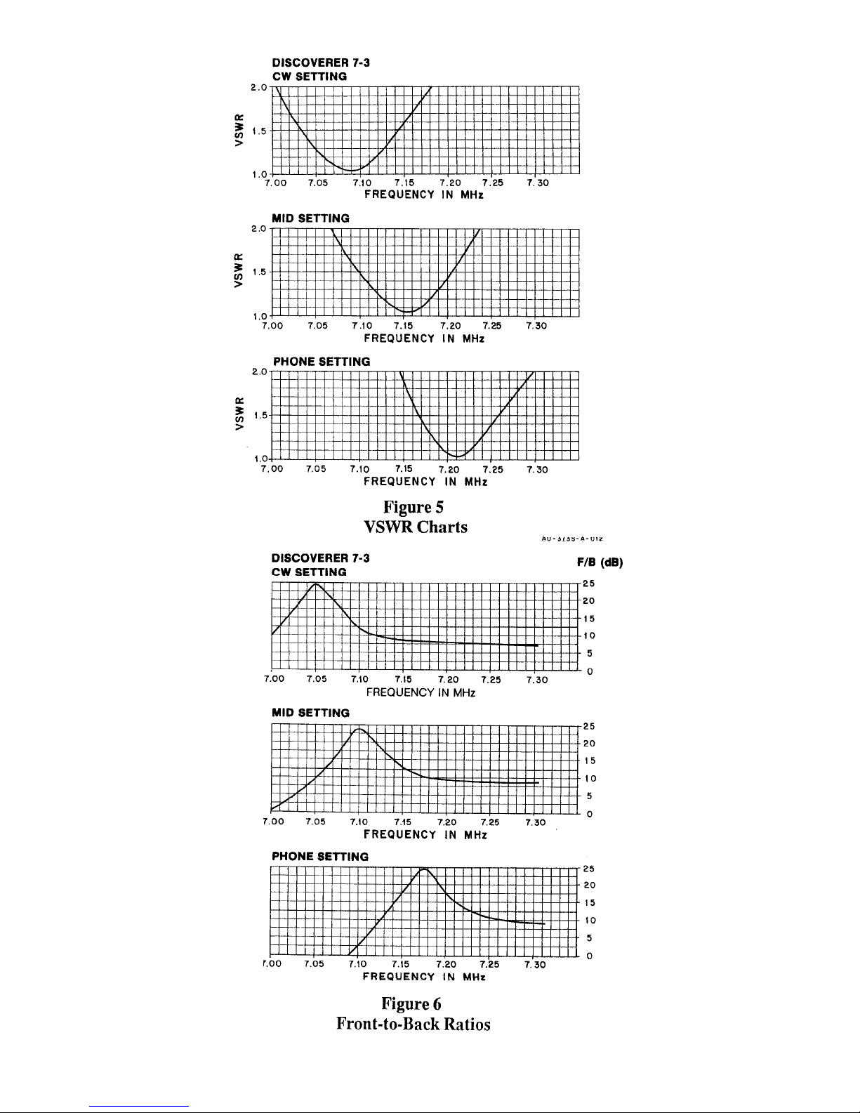
The Discoverer 7-3 is supplied with
dimensions for 3 settings within the 40 meter
Amateur band. The three settings are entitled
CW, MID, and PHONE. The CW setting is
optimized for operation from 7.00 - 7.20
MHz. The MID setting is optimized for
operation from 7.05 - 7.25 MHz, and the
PHONE setting, 7.15 - 7.30 MHz.
Figure 4
Tubing Clamps
The VSWR and Front-to-Back Ratio curves
are shown in Figures 5 and 6. From this
information, choose one of the three settings
to use.
Set the length of the DE5 section (A) to one
of the len
ths shown in Table 1.
Page 13
Page 14
Assembly of the Reflector Element
,
p
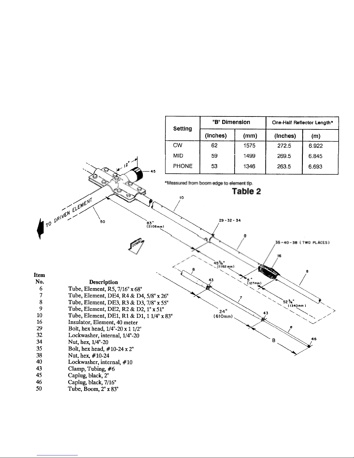
Select the parts listed in Figure 7 and
assemble them as shown. Before tightening
the hardware
make sure that:
R1 (Item No. 10) is inserted completely into
the element-to-boom brackets.
R1 (Item No. 10) is positioned with the small
holes u
and down.
R1 (Item No. 10) is positioned so that the element will be horizontal when installed on the
mast.
Figure 7 Assembly of the
Reflector Element
Page 15
Tighten the anchor bolts (Item No. 28) last.
prop
y
g
p
prop
This will ensure that the element will not slip
on the boom.
Refer to Figure 4 for compression clamp identification and assembly information. Tighten
these clamps securely after setting Item Numbers 6 and 7 to their
er length.
Assembl
of the Director Element
Select the parts listed in Figure 8 and
assemble then as shown, Before tightening
D1 (Item No. 10) is inserted completely into
the element-to-boom brackets.
Set the length of the R5 section ("B") to one
of the lengths in Table 2. The reflector and
driven element must both be adjusted to the
same settin
for proper operation.
NOTE: If you are adding the Discoverer 7-3
Director Kit to a preassembled Discoverer 72, then you only need to readjust the R5
section, "B" dimension, to that shown in
Table 2, and position the reflector element o n
the boom.
D1 (Item No. 10) is positioned with the small
holes u
and down.
D1 (Item No. 10) is positioned so that the element will be horizontal when installed on the
mast.
Tighten the anchor bolts (Item No. 28) last.
This will ensure that the element will not slip
on the boom.
Refer to Figure 4 for compression clamp identification and assembly information. Tighten
these clamps securely after setting Item Numbers 6 and 7 to their
er length.
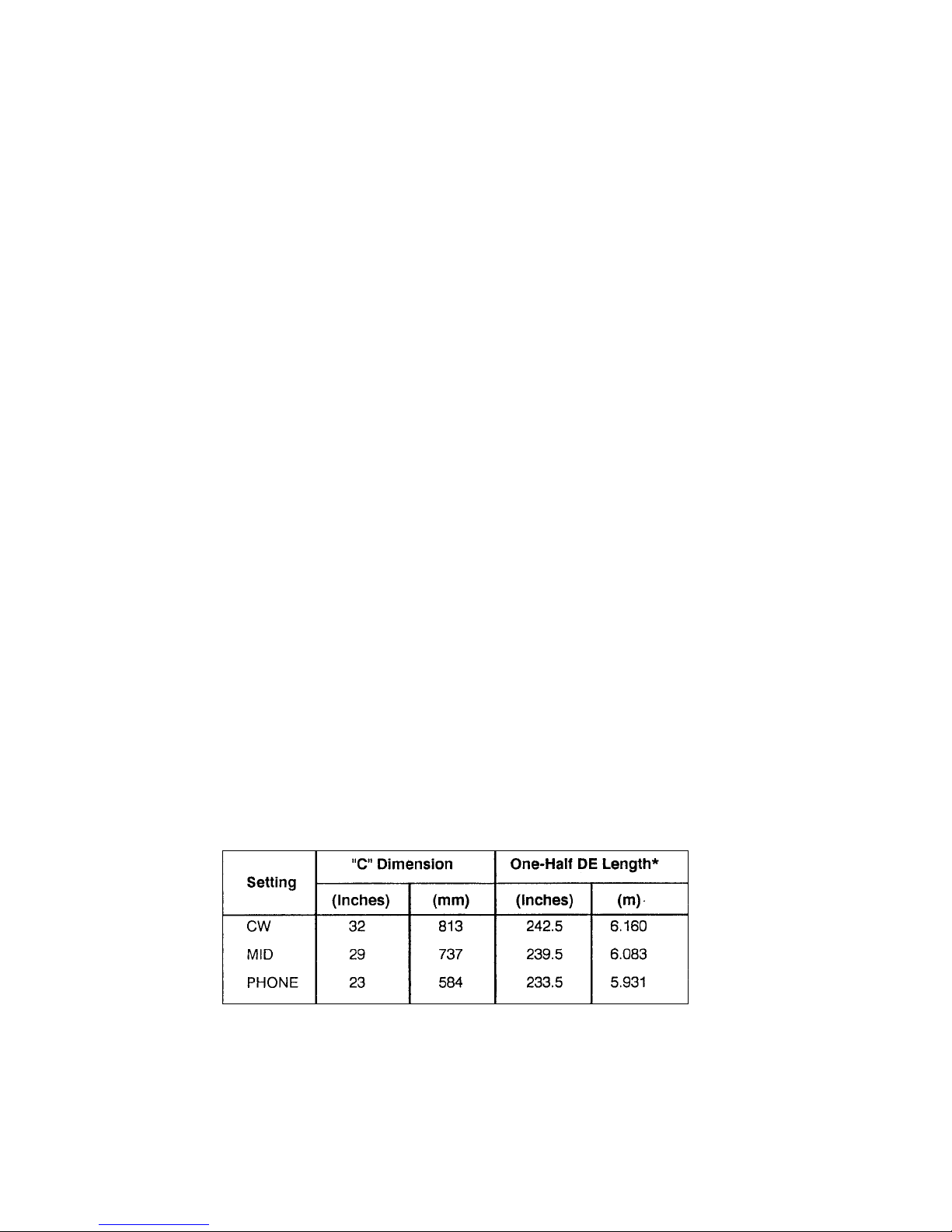
Set the length of the D5 section ("C"
dimension) to one of the lengths in Table 3.
The reflector, director and driven element
must all be adjusted to the same setting for
proper operation.
*Measured from boom edge to element tip.
Table 3
Page 16
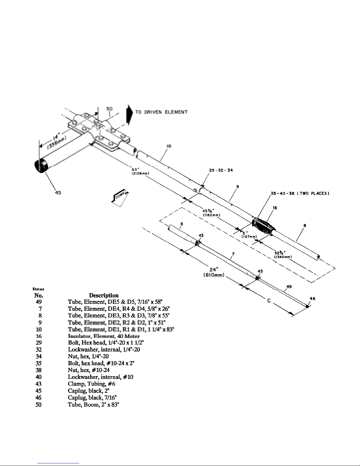
Figure 8 Assembly of the
Directo r E lem ent
Page 17
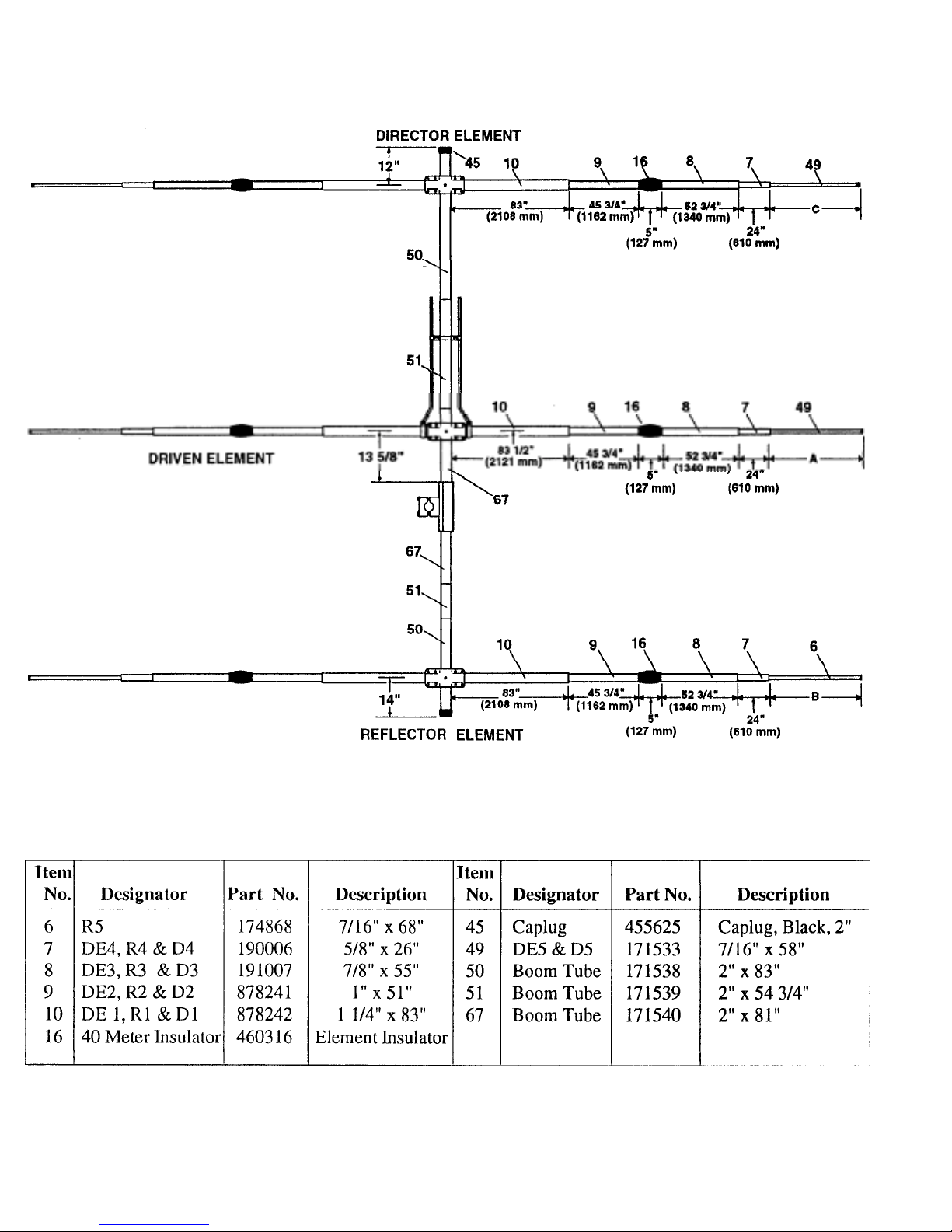
Figure 9 Overall View
of Antenna
Page 18
Driven Element, Reflector and Director
y
pp
y
Linear-Loading Wire Assembl
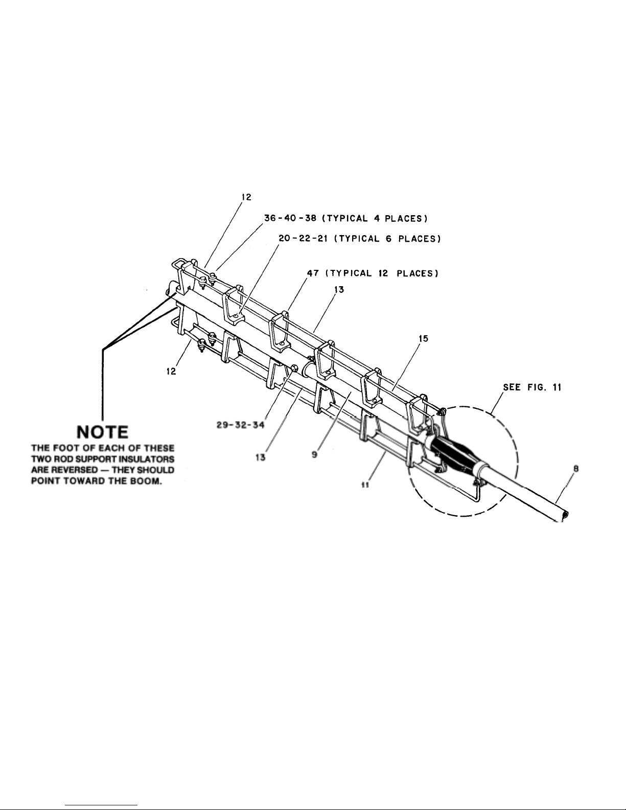
Select the parts listed in Figure 10. Assemble
the linear-loading wire assembly as shown in
Figure 10 for each half of the driven element,
reflector and director.
Start assembling the LLW sections to the element, beginning at the 40 meter insulators.
Position the tubing c lamp (I tem 42) as close as
possible to the 40 meter insulator as s hown in
Detail A, Figure 11. Other clamp and wire
positions will depend upon the final assembl y
of the linear loading wires.
Refer to Figures 11 and 12 for assistance in
identifying and assembling each assembly.
Ite
No.
8
9 Tube Element DE2 R2 & D2 1" x 51" 22 Lockwasher, internal, ' #6
11 "Hairpin", LLWI, 69" 29
12 "Hairpin", LLW2, 28" 32 Lockwasher, internal, 1/4"-20
13 "Hairpin", LLW3, 631/2" 34 Nut, hex, 1/4 -20
15 "Hairpin", LLW5, 631/2" 36 Bolt, hex head, #10-24 x 1/2
20 Bolt, round head, #6-32 x 2" 38 Nut, hex, #10-24
21 Nut, hex, #6-32 40 Lockwasher, internal, #10
Tube, Element, DE3, R3 & D3,7/8" x 55"
Description
NOTE: If the Discoverer 7-2 was previously
assembled, you need only to assemble the
linear loading wires on the new director
element.
Item
No.
47 Insulator , Ro d Su
Figure 10 Linear-Loading
Wire Assembl
Description
Bolt, hex head , l /4" -2 0 x
ort
Page 19
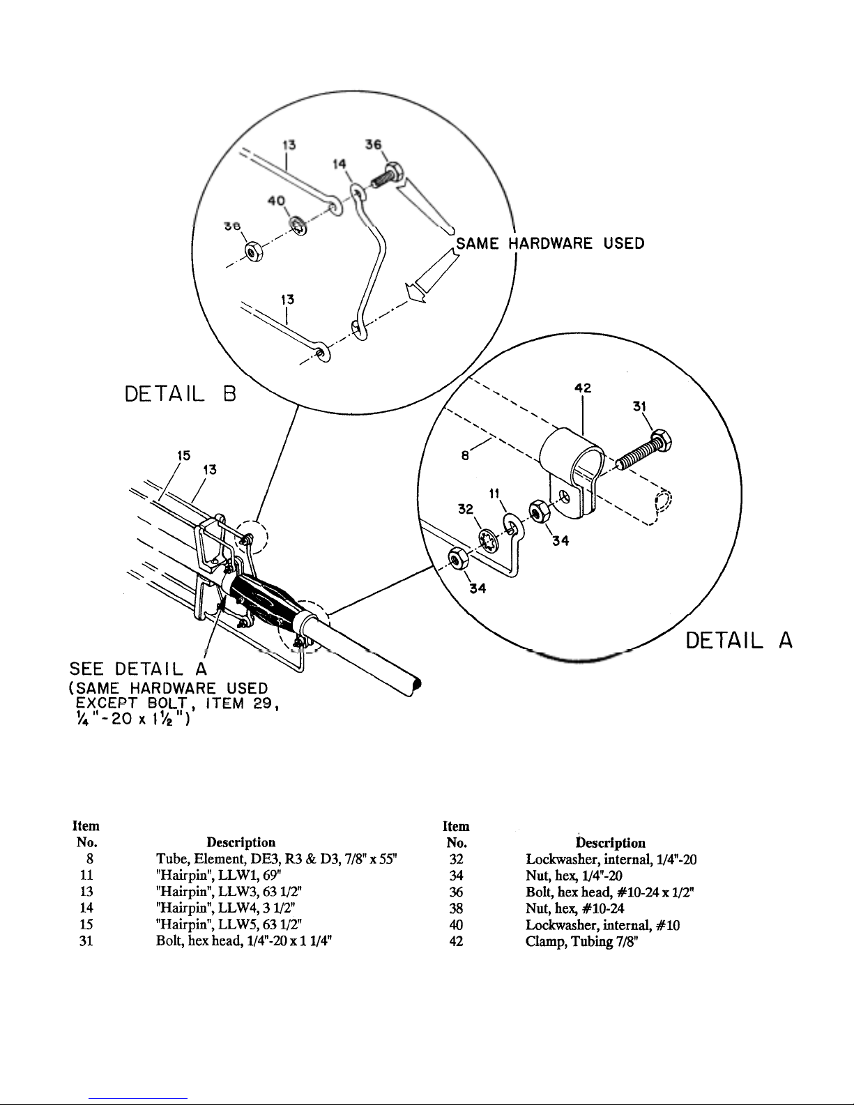
Figure 11 Attachment of Linear-Loading
Wire Assembly Near Insulator
Page 20
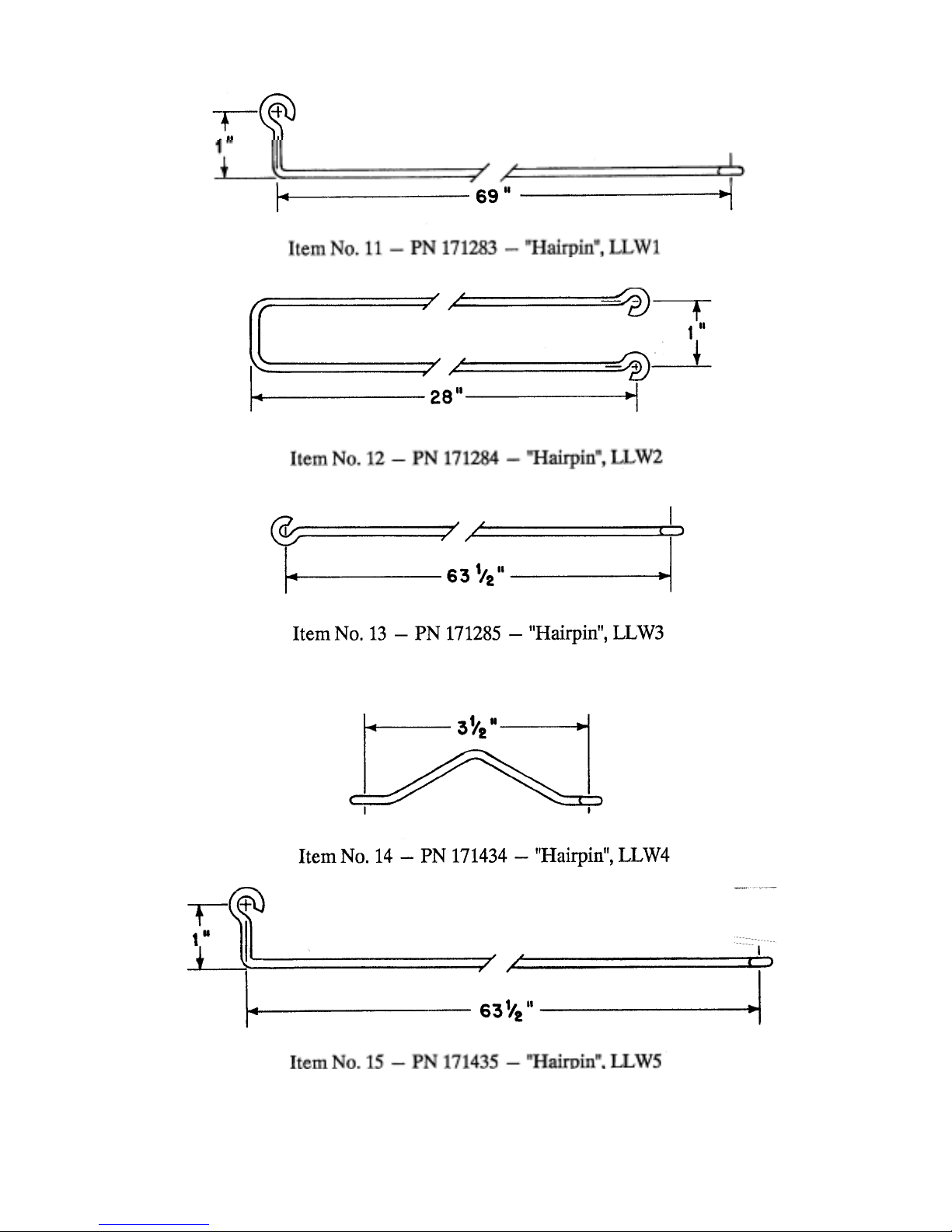
Figure 12 Identification of Linear-Loading
(
)
Wires
LLW
Page 21
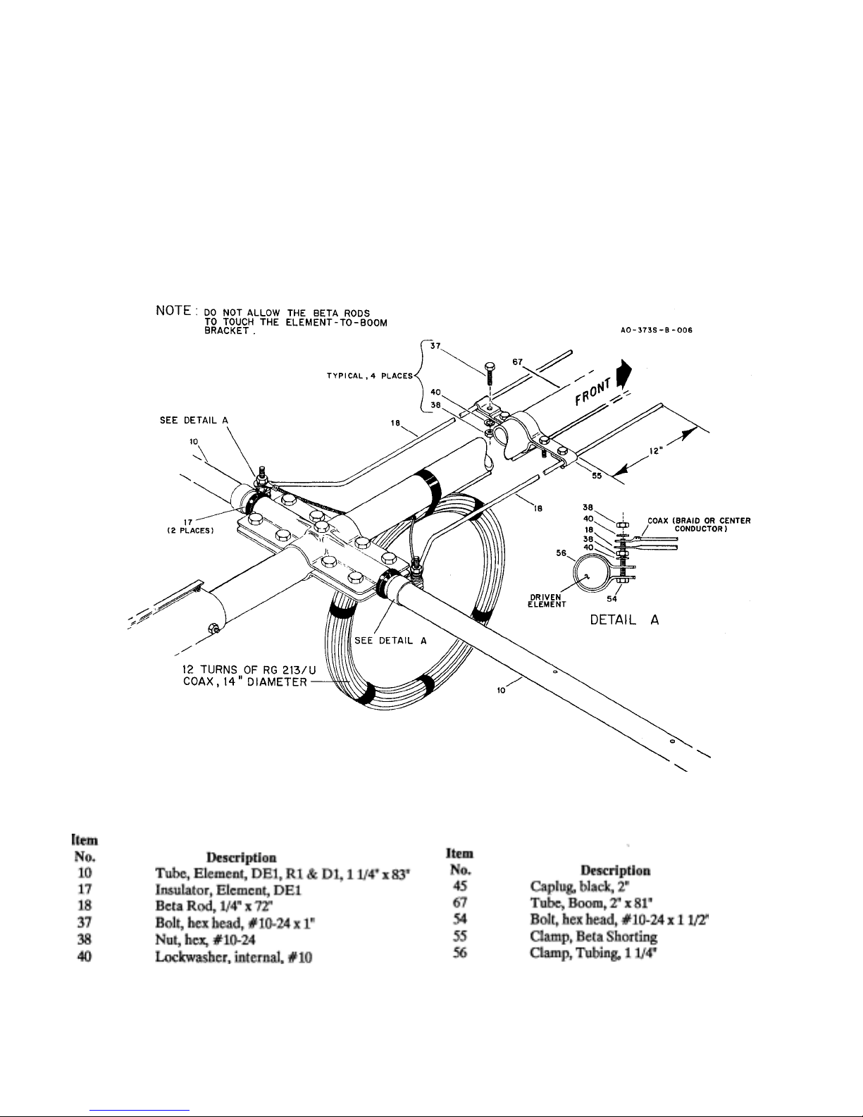
Beta Match Assembl
y
g
Select the parts listed in Figure 13 and Det ail
A and assemble them as shown. After
attaching your coax cable to the feedpoint,
ti
hten all hardware securely.
NOTE: Do not allow the beta rods to touch
the element-to-boom bracket.
Figure 13 Beta
Page 22

Lightning Protection
g
g
,
g
pp
y
(
For proper lightning protection you must
ground your antenna supporting structure.
Grounding will ensure noise-free operation
and low SWR. A proper ground consists of a
1/2" x 8' copper-clad steel ground rod driven
into the ground approximately 12 inches away
from the concrete tower base. Connect the
tower to the ground rod using #8 c opper wire
and commercial noncorrosive ground clamps.
Attachment of Feedline
Strip your coaxial cable (maximum 7 inches)
and install solder lugs (not supplied) and
connect to the driven element as shown in
Figure 13. An RF choke made from 12 turns
of RG-213/u coax in a 14 inch diameter circle
is recommended with a split coax feed.
Seal
An alternative is to use a H y-Gain BN-86 50
ohm balun for easy connection to your coax
cable. "Pigtail" leads of #10 gauge stranded
wire 7 inches long should be used from the
balun to the tubin
clamps.
Use a good quality 50 ohm coaxial
transmission line such as Beldon 8214 (foam)
or Belden 8237, 8267, or 9251 (solid). Take
extra care when soldering connectors to foam
dielectric coaxial cable. Weatherproof all
connector, which will be exposed to rain or
ice
with Coax-Seal® or another similar
Attach the transmission line to the feedpoint
and tighten the hardware securely. Tape the
coax to the boom to ensure
Boom Su
ort Assembl
ood strain relief.
Select the 1 1/4" element compression cla mps
(Item No. 66), the boom support straps (Item
No. 61),1/4"-20 x 13/4" Bolts (Item No. 69),
and 1/4" square nuts (Item No. 33), and
assemble on the director and reflector
elements 10 inches from the center of the
boom. See Figure 14. Tighten the bolts
securely.
cable to each of the four boom supports straps
(Item No. 61) already assembled in the
previous step. See Figure 14. Measure the
distance between the thimble (Item No. 59)
closest to the element and the center of the
turnbuckle (Item No. 57) with the wire taut
and the eyebolts screwed all the way in. This
distance should be approximately 17 feet.
Leave the excess wire, which should be about
2 feet long, to later thread through the
turnbuckle as shown in Fi
ure 14, Detail B.
NOTE: If you have previously assembled the
Discoverer 7-2, then you should disassemble
the mast clamps (Item No. 60), chain links
(Item No. 58) and turnbuckles (Item No. 57)
as these will be used again. Item Numbers 59,
52, 61, and 62 may be discarded from the old
antenna.
Select the two open-end chain links (Item No.
58) and the two mast clamps (Item No. 60).
Thread on chain link into the outer hole of a
mast clamp and then through the t wo e yebolts
attached to the two cable assemblies coming
from the director element. See Figure 14,
Details B and C. Squeeze the chain link
closed with a pair of hand pliers. Do the same
thing for the remaining chain link, mast cla mp
and two cable assemblies coming from the
reflector element.
Hold the two mast clamps together over the
boom-to-mast brackets. If you cannot lift the
two clamps at least 3 feet above the brackets,
or if the wires are not tensioned equally, then
adjust the length of the wires between the
thimbles until these conditions are met. The
turnbuckles should be adjusted for maximum
length.
Tape the mast clamps onto the boom on either
side of the boom-to-mast bracket, so that you
can retrieve them once you and the antenna
are at the top of your tower. The boom
support wires must be routed over the top of
the driven element! The 3/8 inch hardware
may be inserted through each clamp or carried
separately up the tower.
Select the four (4) 20 foot boom support
cables (Item No. 52), wire rope thimbles
Item No. 59) and turnbuckles (Item No. 57).
Coax-Seals® is a registered t r ad emark of Universal Elect ron ics, In c .
Page 23
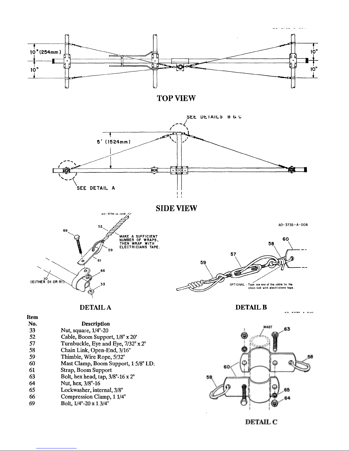
Figure 14 Boom
Support Assembly
Page 24

CHAPTER 4
g
p
g
Installation
Make sure all element compression clamps
and anchor screws are securely tightened.
Also, make sure all beta match hardware is
ti
htened securely and free of corrosion.
IMPORTANT: The Discoverer 7-3 is a very
large and heavy antenna and requires
consideration as to how you are going to get it
to the top of the tower. Thoroughly read this
section before beginning to install your
antenna.
Installation on a Crank-U
Crank the tower down completely or as low
as it will go, and block all sections from
moving by using a 2" x 4" piece of wood or a
solid iron bar for heavier towers. The block
should be inserted through the lattice structure
before the tower is completely down, then the
tower can be cranked down until the block
Use a ladder to reach the top of the tower.
NEVER CLIMB THE LATTICE STRUCTURE OF ANY CRANK-UP TOWER!
Attach the mast to the tower and rotator. (The
cast aluminum boom-to-mast brackets (Item
No. 1) should be installed on the mast as
shown in Figure 15.) Attach a gin pole to the
tower to assist in lifting the Discoverer 7-3.
This antenna weighs approximately 96
pounds, therefore, make sure that your rope is
strong enough and that you have enough help
on the ground to lift.
Tower
held by the ground crew, so that the guide
rope can be retrieved.
Attachin
When the antenna reaches the mast bracket,
the four (4) 5" bolts should be inserted
through the holes in the mast bracket and
secured using 5/16"-181ockwashers and nuts
(Item Nos. 23, 27, & 26). Tighten all bolts
securely. You may wish to use a deep-well
socket set to tighten these bolts. You may
notice a considerable amount of sag in the
boom. This is normal.
The mast clamps may now be untaped from
the boom and attached to the mast, as shown
in Figure 14, Detail C. Loosen the turnbuckles
and slide the entire assembly up the mast until
the boom support wires are straight. Tighten
the 3/8"-16 bolts securely. Take up any slack
in each wire with the turnbuckles, until the
boom is level. When taut, tie off the
turnbuckles. See Figure 14, Detail B. Tape the
transmission line to the boom and mast for
strain relief.
the Antenna to the Mast
Attach the lifting rope to the balance point of
the antenna. The lifting rope should be fed
through the gin pole or other pulley
arrangement attached to the tower. The other
end should be at ground level, avail able to the
ground crew for lifting. Guide ropes may be
loosely looped over the boom ends and used
by the ground crew to guide the antenna awa y
from the tower and ladder. The guide rope's
two loose ends should be
Page 25
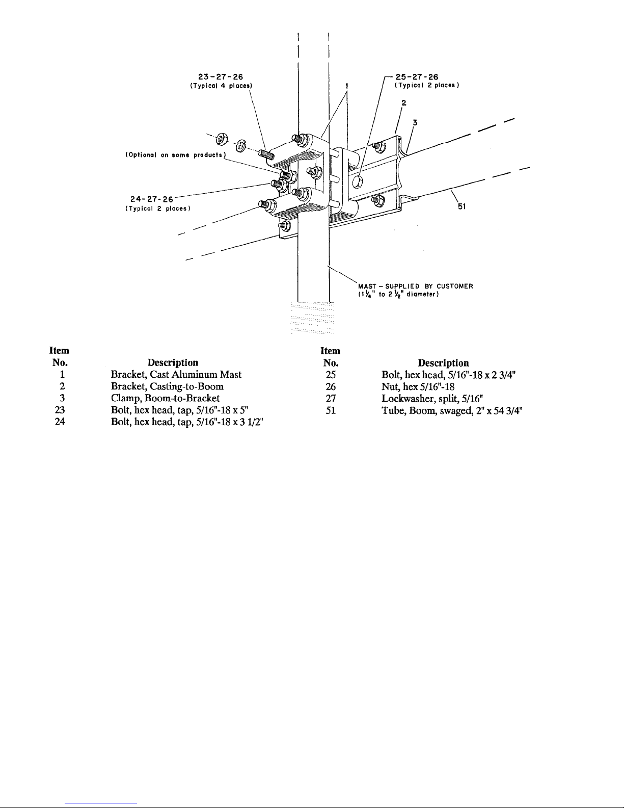
Figure 15 Attaching Boom-to-
yp
Mast Bracket
Other T
es of Towers
When installing the Discoverer 7-3 on a
guyed tower, you may wish to use a different
guide system. If you have insulators on your
guy wires, you will need to keep the antenna
away from the guy wires as well as the towe r.
You may wish to use two ropes attached
together at the top of the tower and attached to
the ground about 15 feet apart.
Installation of this product near power lines
is dangerous. For your safety follow the
instructions.
These two ropes can then be used to slide the
antenna on as if is also being lifted. The two
ropes will need to be far enough from the
tower base to allow some sag and still support
the antenna away from the guy wires.
WARNING
Page 26
Operation
prop
ppy
e
ce
Connect the end of your transmission line to a
good quality SWR meter or Thruline wattmeter and then to your radio. While using
lower power (less than 200 watts output),
check the VSWR across each band from 7.0
to 7.3 MHz. Record this information for
future reference. See Attachment 1 in Chapter
5. Check the VSWR periodically to ensure
er operation.
This completes your installation of the Discoverer 7-3. Ha
DX'ing!
When storing this antenna (or if awaiting
installation), care should be taken not to
damage any assembly. Do not leave the
elements in a grassy area, as wet grass will
VSWR Calculations
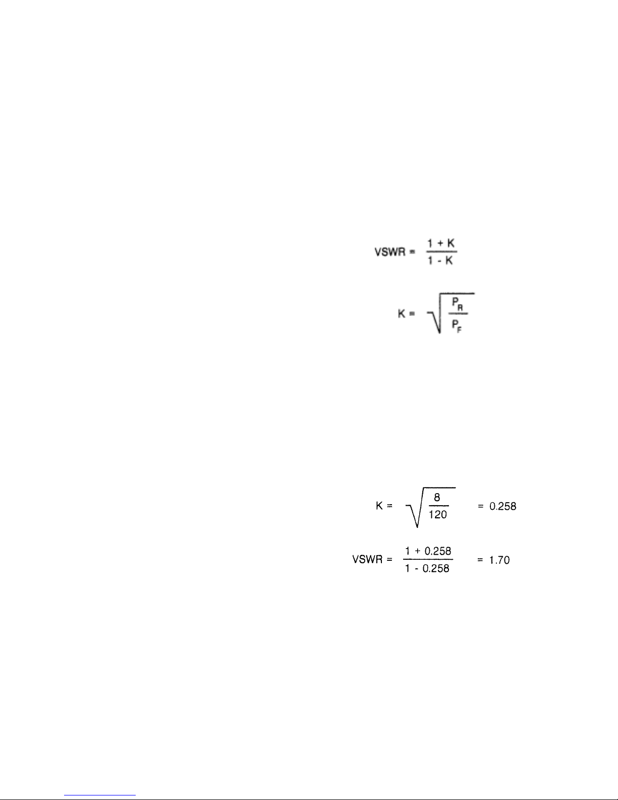
When using a meter, which indicates forward
and reflected power levels, you may wish to
convert these readings to VSWR. The correct
formulas are:
Maint
nan
The Discoverer 7-3 antenna is designed to b e
relatively maintenance free. All hardware, except for seven (7) long bolts used in the
boomto-mast bracket, are made of passivated
stainless steel. The seven long bolts are plated
with a thick layer of cadmium with protective
coating of clear chromate. The internal tooth
type lockwashers used in this antenna are
made of a slightly magnetic grade of stainless
steel. The element compression clamps are
made of T304 passivated stainless steel. All
other metallic parts are aluminum. All
insulators are made of either black
polyethylene, black CycolacO or black fiberfilled styron.
Hy-Gain now recommends genuine PenetroxAO from Burndy Corporation for use as an
antielectrolytic compound within element
assemblies. This prevents aluminum oxide
from forming on the aluminum surface,
thereby maintaining high electrical
conductivity between element sections,
especially in coastal environments. No other
type of conductive paste should be used.
Penetrox-AO can be purchased in most
electrical supply outlets.
A light amount of clear lacquer or an acrylic
spray may be used to coat the exterior surface
of the element assemblies if heavy oxidation
is likely to occur. Heavy oxidation of
aluminum may occur if the antenna is
installed within 5 miles of salt water.
For example, if the forward power is 120
watts and the reflected power is 8 watts
'I'hruline is a registered t rad emark of Bird Electron ics.
Cycolac Is a registered tr ad emark of Borg-Warner. Pen et rox A is a registered trademark of Burndy Corp or at ion .
Page 27

CHAPTER 5
p
SERVICE
Service
If you are encounter technical problems and
need assistance, you should contact Hy-Gain
Customer Service De
All requests, inquires, warranty claims, or
for ordering replacement parts, contact:
Hy-Gain
308 Industrial Park Road Starkville,
Mississippi 39759 USA Phone:
662-323-9538
artment.
Page 28
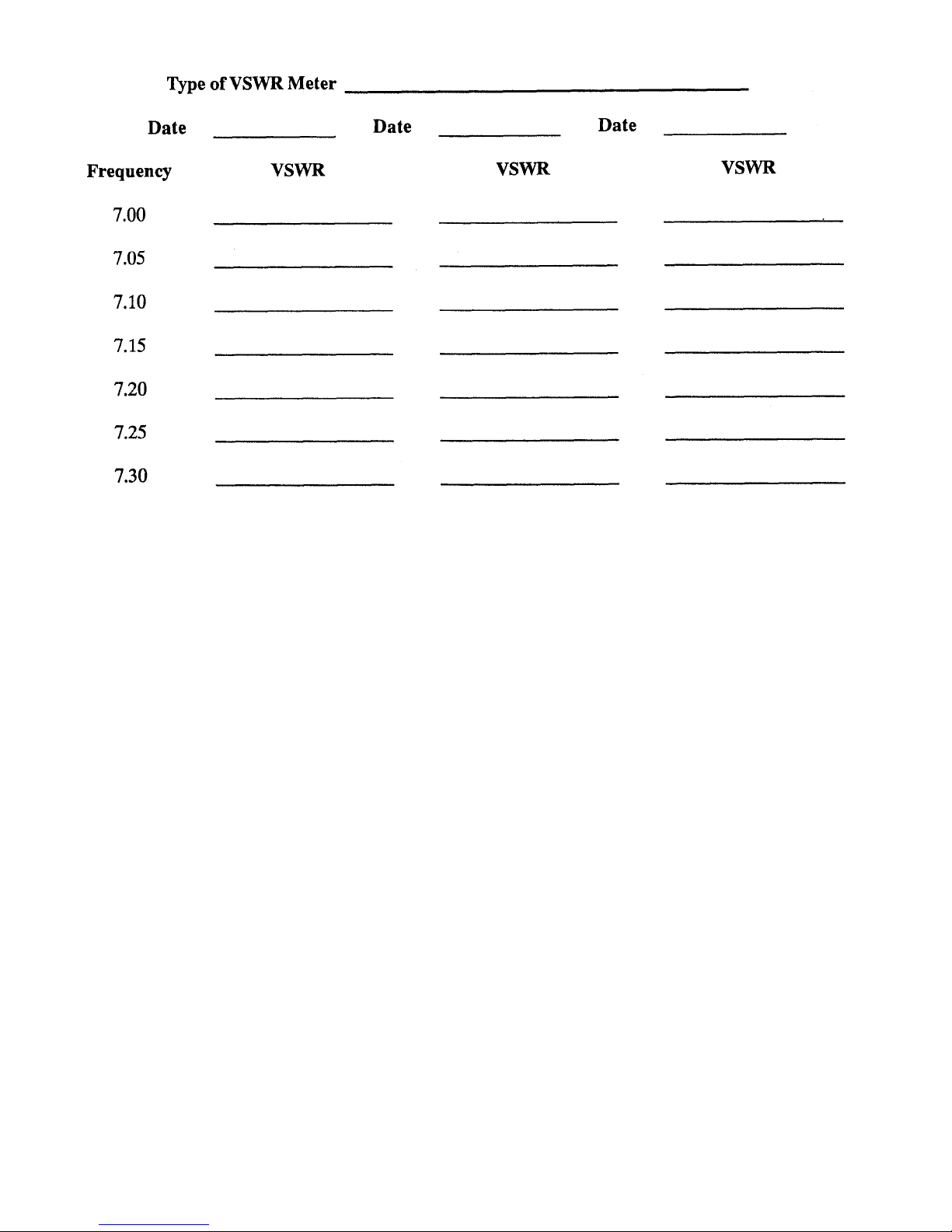
Height of Antenn a: NOTES:
Attachment l
Page 29

NOTE: Item Numbers may not neces sa ri ly be in numerical seque nce and may appear more than
p
g
p
,
(
)
,
p
p
p
p
p
,
,
,
(
)
,
,
,
,
,
,
,
,
,
,
, sp
,
,
,
one time, dependin g on how oft en a pa rt is use d or id en ti ca l p ar ts b ein g pl ac ed in d if f eren t pa rt s
acks.
Item
No.
Part No.
Descriptio n
372S
Qty
373S
1 102734 Bracket, Cast Aluminum Mast ........................................... 2 0
2 172735 Bracket, C as t in
3 172732 Clam
4 165920 Bracket
, Boom-to-Bracket....................................................1 0
Element-to -B o om, #14 .......................................2 0
5
-to-Boom ..................................................1 0
Not Used
6 174868 Tube, Element, R5, 7/16" x 68" ..........................................2 0
7 190006 Tube, Element, DE4, R4 & D4,5/8" x 26" .......................4 2
8 191007 Tube, Element, DE3, R3 & D3,7/8" x 55" .......................4 2
9 878241 Tube
Element, DE2, R2 & D2, 1" x 51"...........................4 2
10 878242 Tube, Element, DE1, RI & D1, 11/4" x 83" ....................4 2
11 171283 "Hair
12 171284 "Hair
13 171285 "Hair
14 171434 "Hair
15 171435 "Hair
16 460316 Insulator
17 465833 Insulator
18 171439 Beta Rod
19
in", LLW 1, 69............................................................. 4 2
in", LLW2, 28"....................................................... ..8 4
in", LLW3, 63 1/2" ....................................................8 4
in", LLW4, 3 1/2".......................................................4 2
in", I LW5, 63 1/2" ....................................................4 2
Element, 40 Meter .............................................4 2
Element, DE1..................................................... 2 0
1/4 x 72"...............................................................2 0
Not Used
48 165919 Bracket, Element-to -B o om, #13 .......................................2 2
49 171533 Tube
Element, DE5 & D5, 7/16" x 58".............................2 2
50 171538 Tube, Boom, 2" x 83"............................................................2 0
51 171539 Tube
52 691081 Cable
67 171540 Tube
70 171541 Tube
Boom, 2" x 54 3/ 4", swaged ......................................2 0
Boom Support, 1/8" x 20 ft...................................... 1 4
Boom, 2" x 81", swaged ............................................. 0 2
Boom, Insert, 13/4" x 711/8 "...................................0 1
878245 Parts Pack, 3728, Hardware ................................................ 1 0
878250 Parts Pack
20 500143 Bolt
373S, Hardware ................................................ 0 1
round head, #6-32 x 2" .........................................26 12
21 555888 Nut, hex, #6-32 ...............................................................26 12
22 565889 Lockwasher
23 500153 Bolt
24 500154 Bolt
hex head, tap, 5/16"-18 x 5"....................................4 0
hex head, tap, 5/16"-18 x 3 1/2...............................3 0
internal, #6...............................................26 12
25 506968 Bolt, hex head, 5/16"-18 x 2 3/4".....................................2 0
68 506966 Bolt, hex head, 5/16"-18 x 21/2".....................................0 2
26 555747 Nut, hex, 5/16"-18.............................................................9 4
27 564792 Lockwasher
28 500156 Bolt
29 504098 Bolt
30 505266 Bolt
1/4"-20 x 3/8"............................................................6 2
hex head, 1/4"- 20 x 11/2 ........................................ 8 4
hex head, 1/4"- 20 x 3/4" ........................................20 8
lit, 5/16"...................................................9 4
Page 30

Item
p
Qty
,
,
,
,
,
,
q
,
(
)
p,
p
(
)
p,
,
plug
plug,
,
pp
, Ey
p
,
p
p,
p,
,
,
,
,
,
No. Part No. Descri
tion
372S 373S
878250 Parts Pack, 373S, Hardware (cont.)
31 506518 Bolt
hex head, 1/4"-20 x 11/4 ....................................... 4 4
53 505734 Bolt, hex head, 1/4"-20 x 21/2......................................... 2 0
69 505763 Bolt
hex head, 1/4"-20 x 13/4......................................... 0 6
32 562961 Lockwasher, internal, 1/4"-20........................................ 46 20
33 551367 Nut, square, 1/4"-20 .........................................................4 4
34 554099 Nut
35 500157 Bolt
36 500158 Bolt
37 504069 Bolt
hex, 1/4"-20............................................................44 20
hex head, # 10-24 x 2".............................................8 4
hex head, # 10-24 x 1/2" ......................................26 14
hex head, # 10-24 x 1".............................................4 2
54 500159 Bolt, hex head, #10-24 x 11/2 "……..............................2 0
38 554071 Nut, hex, # 10-24 ............................................................42 20
39 555693 Nut, s
40 565697 Lockwasher
41
uare, #10-24.........................................................4 2
internal, #10.............................................42 16
Not Used
878246 Parts Pack, 372S, Clamps ....................................................1 0
42 169339 Clam
43 358756 Clam
44
Tubing 7/8" ..........................................................8 0
,Tubing, #6............................................................8 0
Not Used
55 163371 Clamp, Beta Shor ti ng ......................................................2 0
56 171333 Clam
878247 Parts Pack
45 455625 Ca
46 455644 Ca
47 463642 Insulator
878248 Parts Pack, 3725, Boom Su
57 351243 Turnbuckle
58 351244 Chain Link, O
59 351700 Thimble
60 381100 Mast Clam
61 381253 Stra
62 388861 Clam
63 500152 Bolt
30 505266 Bolt
Tubing, 11/4 ....................................................... 2 0
3725, Insulators ................................................ 1 0
, black, 2"...............................................................2 0
black, 7/16" .........................................................4 0
Rod Support ..................................................48 0
ort .......................................1 0
e and Eye, 7/32" x 2" .............................2 0
en-End, 3/16".........................................2 0
Wire Rope, 5/32".............................................4 0
, Boom Support, 5/8.................................... 2 0
Boom Support ...................... :.............................. 2 0
Boom Support, 2" LD. .......................................2 0
hex head, 3/8"-16 x 2" .............................................2 0
hex head, 1/4"-20 x 3/4.......................................... 2 0
32 562961 Lockwasher, internal, 1/4" ..............................................2 0
34 554099 Nut
64 555694 Nut
65 565696 Lockwasher
hex, 1/4"-20...............................................................2 0
hex, 3/8"-16...............................................................2 0
internal, 3/8" ..............................................2 0
Page 31
Item
p
p
(
)
pp
p
p
p
No.
Part No.
Description
3725
Qty
373S
878251
42 169339 Clam
43 358756 Clam
44
Parts Pack, 3735, Clamps and Miscellaneous ..................0 1
, Tubing 7/8" ..........................................................0 4
, Tubing, #6...........................................................0 4
Not Used
57 351243 Turnbuckle, Eye and Eye, 7/32" x 2" .............................0 2
46 455644 Caplug, black, 7/16" .........................................................0 2
47 463642 Insulator, Rod Su
59 351700 Thimble, Wire Ro
61 381253 Stra
66 380422 Clam
, Boom Support ....................................................... 0 4
, Compression, 11/4'1 ...........................................0 4
ort ...................................................0 28
e, 5/32".............................................0 8
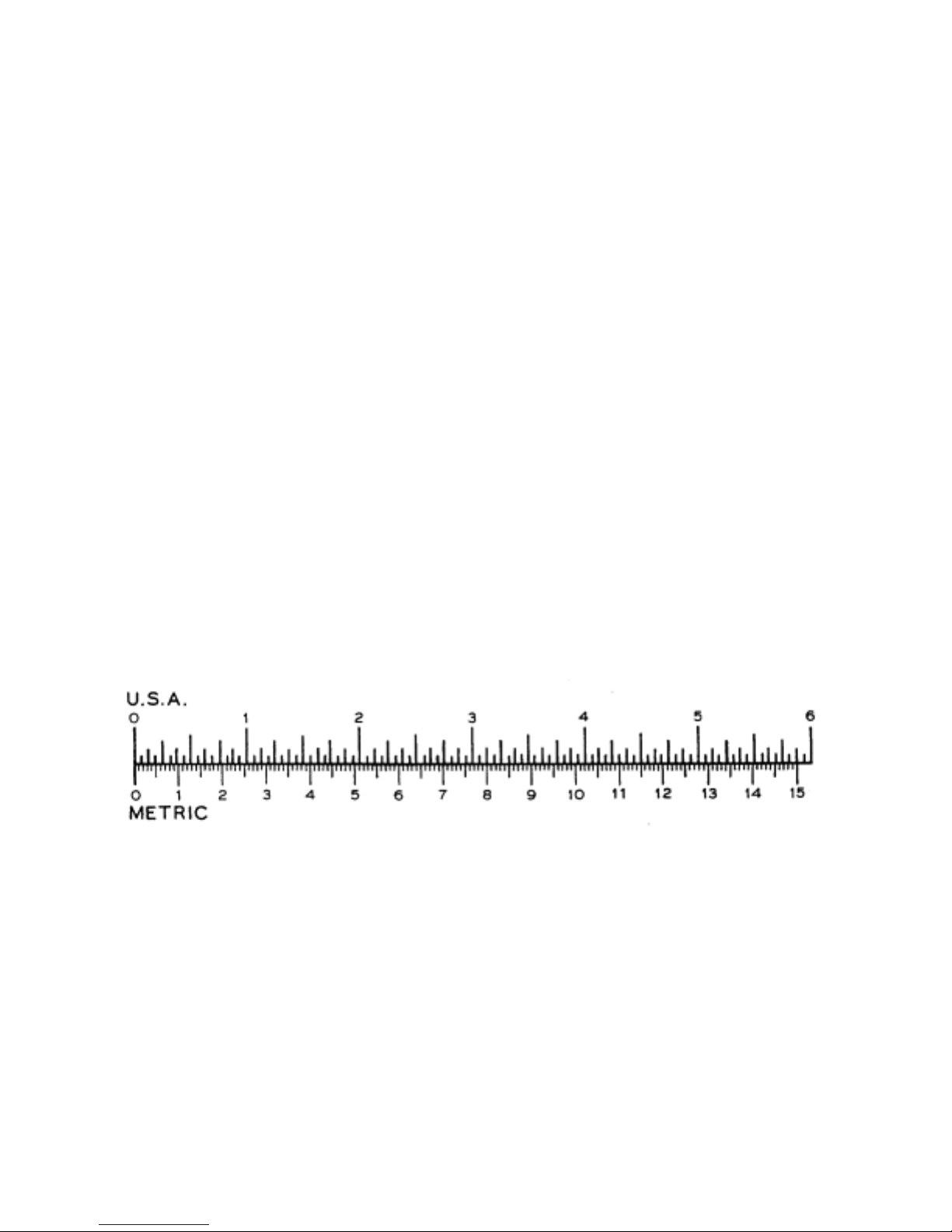
Use this scale to identify lengths of bolts, 1 inch (1") = 2.54. cm
diameters of tubes, etc.. The American inch (") 1 foot (1') = 30.48 cm
'
 Loading...