

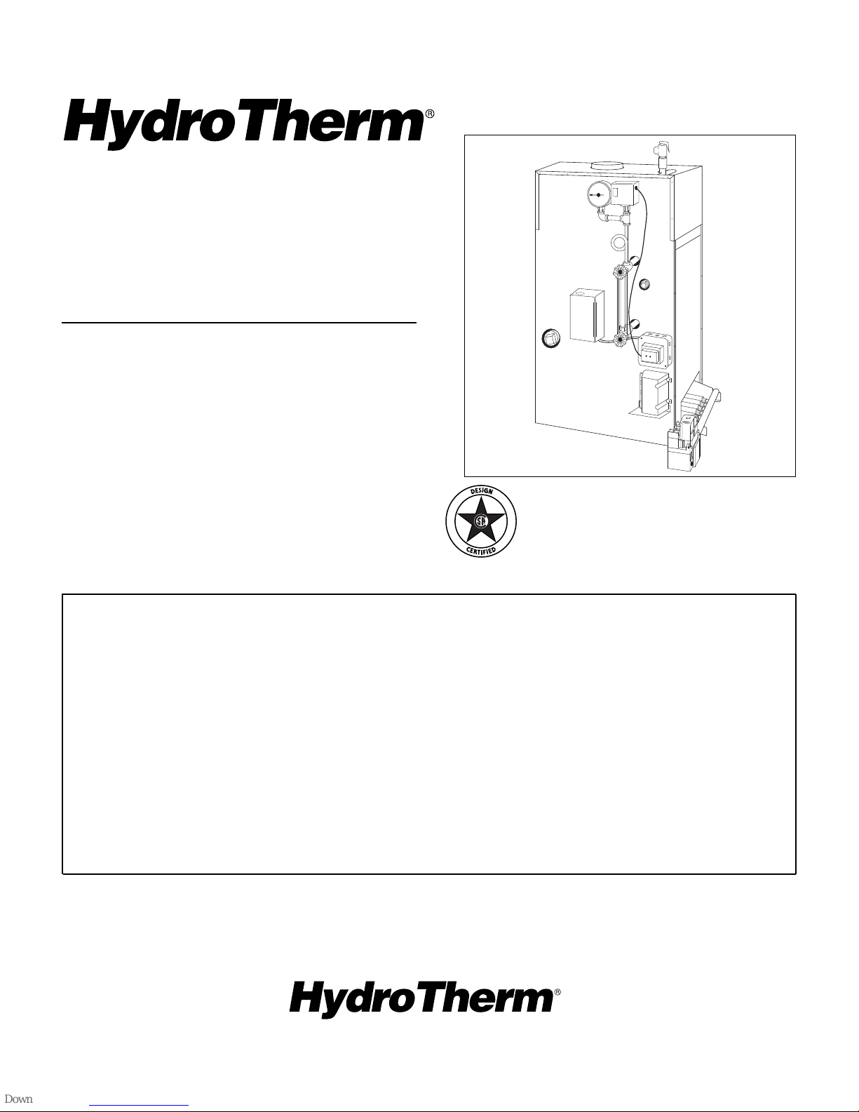
HydroTherm VS-85B, VS-110B, VS-135B, VS-165B Installation, Operation & Maintenance Manual And Replacement Parts List
Page 1
VSB2-605
42-9187
VS-B SERIES
INSTALLATION, OPERATION
& MAINTENANCE MANUAL
AND REPLACEMENT
PARTS LIST
Gas-Fired Steam
Cast Iron Boilers
85,000 to 165,000 Btuh Input
Intermittent
Pilot/Vent Damper
And
Standing Pilot/Vent Damper
260 NORTH ELM ST. • WESTFIELD, MA 01085 • (413) 564-5515 • FAX (413) 568-9613
5211 CREEKBANK ROAD • MISSISSAUGA, ONTARIO L4W 1R3 • (905) 625-2991 • FAX (905) 625-6610
SECTION 1: INTRODUCTION
Code Compliance ..........................................................2
Venting Requirements ...................................................2
Chimney Requirements .................................................3
Combustion Air Requirements ......................................3
Water Treatment ............................................................3
Shipment of Boiler .........................................................3
SECTION 2: BOILER INSTALLATION
Step 1: Locating/Setting Boiler ......................................4
Step 2: Installing Steam Piping .....................................5
Step 3: Installing Hydronic Components .......................5
Step 4: Venting Boiler.....................................................6
Step 5: Installing/Testing Gas Piping..............................7
Step 6: Wiring Boiler ......................................................9
SECTION 3: START-UP & OPERATION
Sequence Of Operation................................................11
Prior To Start-Up ..........................................................11
Start-Up & Adjustments................................................11
SECTION 4: MAINTENANCE
Before Each Heating Season .......................................15
How To Change Orifices...............................................16
Heating System Problems & Causes ...........................16
REPLACEMENT PARTS ..............................................17
TABLE OF CONTENTS
Page 2

2
SECTION 1: INTRODUCTION
The following terms are used throughout this manual to
bring attention to the presence of potential hazards or to
important information concerning the product:
CAUTION: Indicates a potentially hazardous situation which, if not avoided, may result in minor injury
or property damage.
NOTE: Used to notify of special instructions on
installation, operation or maintenance which are
important to equipment but not related to personal
injury hazards.
CODE COMPLIANCE
Boiler installations must conform to the requirements of
the authority having jurisdiction or, in the absence of
such requirements, to the National Fuel Gas Code ANSI
Z223.1-latest edition. Where required by the authority
having jurisdiction, the installation must also conform to
the American Society of Mechanical Engineers Code for
"Controls and Safety Devices for Automatically Fired
Boilers", ANSI/ASME CSD-1.
All electrical wiring must be in accordance with National
Electric Code ANSI/NFPA No.70-latest edition and any
additional state or local code requirements. If an external source is utilized, the boiler, when installed, must be
electrically grounded in accordance with requirements of
the authority having jurisdiction or, in the absence of
such requirements, with the National Electrical Code,
ANSI/NFPA No.70-latest edition. UL listed power limited
circuit cable is almost universally approved for safety
controls on heating equipment, either internally or externally, without protection of conduits or raceway.
DANGER: Indicates an imminently hazardous situation which, if not avoided, will result in death,
serious injury or substantial property damage.
WARNING: Indicates a potentially hazardous situation which, if not avoided, could result in death,
serious injury or substantial property damage.
VENTING REQUIREMENTS
When connecting to gas vents or chimneys, vent installations shall be in accordance with Part 7, Venting of
Equipment, of the National Fuel Gas Code, ANSI
Z223.1-latest edition, or applicable provisions of the local
building codes.
Vent connectors serving appliances vented by natural
draft shall not be connected into any portion of mechanical draft systems operating under positive pressure.
When two or more appliances vent into a common flue,
the area of the common flue should be at least equal to
the area of the largest flue plus 50% of the areas of the
additional flue or vent connectors.
When existing boiler is removed from common venting
system, common venting system is likely to be too large
for proper venting of appliances remaining connected to
it. At time of removal of existing boiler, the following
steps shall be followed with each appliance remaining
connected to the common venting system placed in
operation, while other appliances remaining connected
to the common venting system are not in operation:
1. Seal all unused openings in common venting system.
2. Visually inspect the venting system for proper size and
horizontal pitch and determine there is no blockage or
restriction, leakage, corrosion and other deficiencies
which could cause an unsafe condition.
3. Insofar as is practical, close all building doors and win-
dows and all doors between the space in which the
appliances remaining connected to the common venting
system are located and other spaces of the building.
Turn on clothes dryers and any appliance not connected
to the common venting system. Turn on any exhaust
fans, such as range hoods and bathroom exhausts, so
they will operate at maximum speed. Do not operate a
summer exhaust fan. Close fireplace dampers.
4. Place in operation the appliance being inspected. Follow the lighting instructions. Adjust thermostat so appliance will operate continuously.
5. Test for spillage at draft hood relief opening after 5
minutes of main burner operation. Use the flame of a
match or candle, or smoke from cigarette, cigar or pipe.
6. After it has been determined that each appliance
remaining connected to common venting system properly vents when tested as outlined above, return doors,
windows, exhaust fans, fireplace dampers and any other
gas-burning appliance to previous conditions of use.
7. Any improper operation of the common venting system should be corrected so the installation conforms
with National Fuel Gas Code, ANSI Z223.1-latest edition. When resizing any portion of the common venting
system, the common venting system should be resized
to approach the minimum size as determined using the
appropriate tables in Appendix G in the National Fuel
Gas Code, ANSI Z223.1-latest edition.
Page 3

3
CHIMNEY REQUIREMENTS
DANGER: A chimney which does not meet modern
safety standards will result in a fire or deadly carbon
monoxide poisoning of the building residents.
Chimney condition is of paramount importance for a
safe and efficient boiler installation. All new and replacement installations must include a chimney inspection by
a qualified individual or agency. Chimney construction
materials must be compatible with the fuel being used.
Particular attention should be paid on all oil-to-gas conversions. Soot may have accumulated in chimney and/or
degraded chimney liner. Most utilities require complete
chimney cleaning. Others may require installation of new
liner, spill switches or other chimney upgrades. Check
with local utility for required safety precautions.
COMBUSTION AIR REQUIREMENTS
Provisions for combustion air must be in accordance
with the National Fuel Gas Code ANSI Z223.1 - latest
edition, as well as all applicable local codes. If the boiler
is installed in an unconfined space, adequate air will be
available via normal infiltration. However, if building construction is unusually tight or the boiler is installed in a
confined space (a space whose volume is less than 50
cubic feet per 1000 Btu/hr of gas input for all fuel burning equipment), adequate air for combustion must be
provided by two openings: one located about 6” below
the ceiling, the other about 6” above the floor. When
communicating directly with the outside or through a
vertical duct, each opening must have a minimum free
area of one square inch per 4000 Btu/hr of gas input.
Horizontal ducts to the outside must have a minimum
free area of one square inch per 2000 Btu/hr of gas
input. When ventilation is provided by openings in doors,
etc. to adjoining spaces having adequate infiltration,
each opening must have a minimum free area of one
square inch per 1000 Btu/hr of gas input.
NOTE: Boiler employs atmospheric combustion.
Combustion air must not be contaminated with halogenated hydrocarbon vapors, aerosol propellants or
freon. Otherwise, boiler heat exchanger will be subject to corrosion, reducing boiler life.
WATER TREATMENT
Water treatment is recommended in areas where water
quality is a problem. A local water treatment company
should be consulted to determine the requirements for
your particular system and locality.
NOTE: Boiler is not for use in systems where water
is replenished. Minerals in the water can build up on
the heat transfer surfaces and cause overheating
and subsequent failure of the heat exchanger.
NOTE: Boiler utilizes EPDM synthetic rubber seals.
Water treatment chemicals and system cleaning
chemicals must be compatible with this and all
other construction materials.
SHIPMENT OF BOILER
Each boiler is shipped in a single carton.
Optional Vent Damper
When ordered, the vent damper is shipped in an individual carton packaged with the boiler. Mounting of the
damper and flue outlet extension are required.
WARNING: Adequate fresh air must be provided for
combustion. Improper boiler operation and inadequate venting of deadly flue gases may otherwise
result.
Page 4
4
SECTION 2: BOILER INSTALLATION
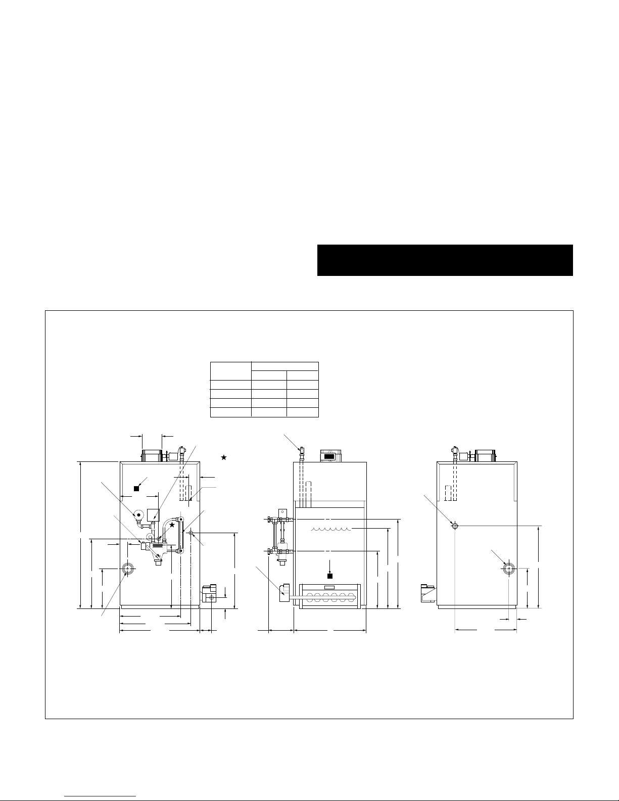
Boiler may be installed in an alcove (see dimensions in
Figure 2.1). Locate boiler so connecting flue pipe
between draft hood and chimney is as short as possible.
Observe the following minimum clearances to combustibles: 18" on sides...alcove at front...28" at top 18" at
rear...6" from flue pipe in any direction. Maintain a minimum 1” clearance between hot water piping and combustible materials. Local code requirements may specify
greater clearances and must be adhered to.
Remove boiler from carton and set it in position. Install
on non-combustible floor only, unless local codes permit
use and fabrication of a fireproof base (see Figure 2.2).
Remove all packing material from boiler. Check that
burners, draft diverter and controls are in proper position.
Boiler shall be installed such that the gas
ignition system components are protected
from water (dripping, spraying, rain, etc.)
during appliance operation and service
(low water cut-off replacement, condensate
trap, control replacement.).
NOTE: Do not loosen tie rods on boiler absorption
unit. They are intended to accommodate thermal
expansion. Loss of boiler's structural integrity and
water leaks/damage may result.
FIGURE 2.1: MODEL VS-B BOILER DIMENSIONS
WARNING: Never install boiler on carpeting as heat
damage and/or fire may result.
STEP 1: LOCATING/SETTING BOILER
15 3/8"
18 7/8"
18 7/8"
22 3/8"
PRESS.
RELIEF VALVE
GAS
VALV E
6 3/4"
DIMENSIONS
A
PRESS.
GAUGE
LOW
WATER
CUT-OFF
41"
2 1/2"
21"
14 3/4"
2" RETURN
FRONT
BOILER
MODEL
VS-85
VS-110
VS-135
VS-165
B
SPILL SWITCH
9 7/8"
16 1/2"
18 1/8"
21 7/8"
-LEFT SIDE VIEW- -FRONT VIEW- -RIGHT SIDE VIEW-
NOTE: OPTIONAL FLOAT LOW WATER CUT-OFF SHOWN.
20"
PRESSURE CONTROL
PROBE LOCATION
FOR ELECTRIC
2" STEAM
SUPPLY
WATER
LEVEL
INDICATOR
1/2"
PLUGGED
TAPPING
3 3/8"
2 3/8"
LWCO
23 1/4"
3"
MINIMUM CLEARANCES
WATER
LINE
A
TO COMBUSTIBLES
Top: 28"
Rear: 18"
Left & Right: 18"
Front: ALCOVE
3/4" PLUGGED
TAPPING
23 1/4"
18 1/4"
26 7/8"
2" RETURN
REAR
18 1/8"
14 3/4"
B
5"
6"
6"
7"
ROLLOUT SWITCH
23 7/8"
2 1/2"
Page 5
5
STEP 2: INSTALLING STEAM PIPING
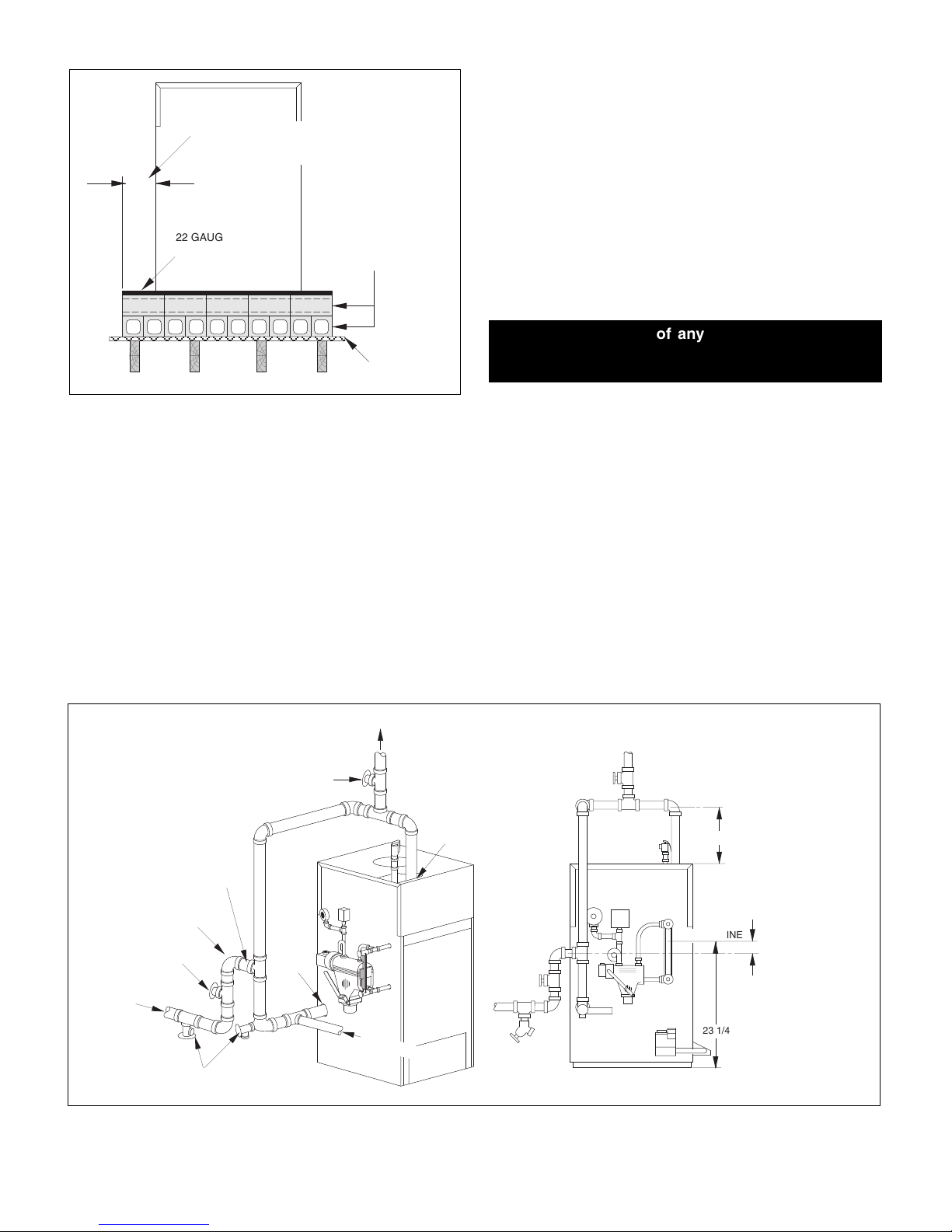
Typical piping connections are shown in Figure 2.3. All
external piping must be supported by hangers, not by
the boiler or its accessories.
Supply outlet must run full size from the boiler to a header at least 24" above top of boiler. Condensate return
piping should be connected to boiler through a "Hartford
Loop." Install gate valves in supply and return.
Proper steam piping practices must be followed at all
times. Maintain proper clearances between piping and
combustible material.
The supply and return lines should be equipped with
drain cocks to drain sediment and sludge from lowest
points of boiler.
STEP 3: INSTALLING
HYDRONIC COMPONENTS
A low-water cutoff must be installed to protect the unit
from dry fire.
Screw extension nipple into 3/4" tapping on top of the
absorption unit and install relief valve into top of nipple
with the spindle in the vertical position (i.e., with the
valve discharge in the horizontal).
Most localities require the discharge piping to terminate
within 6" of the floor. Check local code requirements if in
doubt. Discharge piping must be of same size or larger
than the relief valve outlet and should be run as short
and straight as possible. Elbows in the discharge piping
should be placed as close to the valve as possible. If
valve discharge is to be drained away, the discharge piping must not be hard-piped to the drain piping (i.e., an
open funnel or similar arrangement must be used).
CAUTION: Piping must be installed from the relief
valve discharge so there will be no danger of scalding personnel.
FIGURE 2.2: RECOMMENDED FIREPROOF BASE
6" OVERHANG OF BLOCKS
FIGURE 2.3: TYPICAL STEAM BOILER PIPING
WARNING: No Valve of any type may be installed
between the boiler and the relief valve to prevent
accidental explosion from over-pressure.
AND SHEETMETAL ALL
AROUND
6"
22 GAUGE
SHEETMETAL
4" HOLLOW CLAY
TILE (TWO COURSES)
OPENINGS THRU BLOCKS
IN TOP COURSE TO
BE AT 90° ANGLE
TO OPENINGS THRU
BOTTOM COURSE
FLOOR
MUST BE CLOSE
NIPPLE
HARTFORD
LOOP
GATE
VALVE
RETURN
DRAIN
COCKS
STEAM
SUPPLY
GATE VALVE
SUPPLY
TAPPING
3" NPT
RETURN
TAPPING
2" NPT
COLD WATER FILL
12" MIN.
WATER LINE
C/L OF HARTFORD
LOOP TO BE 2"
BELOW WATER
23 1/4"
LINE
Page 6
6
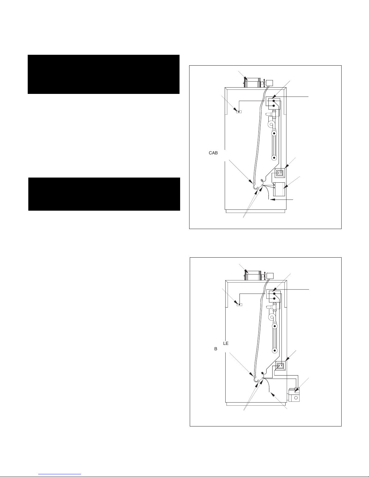
A factory-mounted spill switch is provided on all VS-B
boilers (see Figures 2.4 & 2.4A).
The flue or vent connectors must be installed flush with the
inside chimney liner surface and sealed in place with furnace cement. Horizontal positions of the single wall and
type B venting systems shall be supported by use of strap
hangers or their equivalent. Vent supports should be
placed a maximum of 15 feet apart and as required to prevent sagging. The vent connectors shall be pitched 1/4" per
foot upwards towards the chimney or vent termination.
INSTALLING VENT DAMPER
The vent damper must be mounted directly on top of the
draft diverter.The vent outlet extension must be installed
between the damper and the outlet to allow the damper
plate to open and close.
Locate the motor on the right side and position the cable so
that it does not touch the metal surface of the draft diverter
(see Figure 2.4). If necessary, turn angle connector on
vent damper upward until cable clears; tighten locknut to
secure.The direction of the flow arrow imprinted on the vent
damper must point upward. The damper position indicator,
which is located on the side of the vent damper opposite
the motor, must be visible.
CAUTION: A minimum of 6" between vent damper and
combustible materials must be maintained. The vent
damper must be accessible for servicing and checking
position indicator.
Remove hairpin shipping clip which holds damper blade in
closed position and observe that damper blade rotates
slowly to open position. Do not force it closed as it may
damage the gear train and void the warranty. The blade
should move freely and without obstruction.
Secure the vent damper housing to the draft diverter outlet
with sheet metal screws or pop rivets. Refer to Figure 2.5
for fastener locations. Install flue pipe over top of vent
damper and secure to damper housing with sheet metal
screws or pop rivets.
Attach vent damper cable to cable clamp on boiler front
panel and join the Molex connector (see Figures 2.4 &
2.4A).
TRANSFORMER
PILOT
CONTROL
VENT DAMPER
PRESSURE
CONTROL
THERMOSTAT
CONNECTION
DK. BLUE
SPILL
SWITCH
CABLE
BRACKET
THERMOSTAT
CONNECTION
MOLEX
CONNECTORS
STEP 4: VENTING BOILER
DANGER: Draft diverter, vent outlet and vent
damper as supplied must not be altered in any way,
as proper boiler operation would be jeopardized.
Flame rollout, fire or carbon monoxide poisoning
will result.
DANGER: Only the boiler may be served by the
vent damper. Do not attempt to use it to vent an
additional appliance. This will cause fire or carbon
monoxide poisoning.
FIGURE 2.4: VENT DAMPER INSTALLATION
FOR INTERMITTENT PILOT
TRANSFORMER
GAS
VALVE
VENT DAMPER
PRESSURE
CONTROL
THERMOSTAT
CONNECTION
DK. BLUE
SPILL
SWITCH
CABLE
BRACKET
THERMOSTAT
CONNECTION
MOLEX
CONNECTORS
FIGURE 2.4: VENT DAMPER INSTALLATION
FOR STANDING PILOT
Page 7
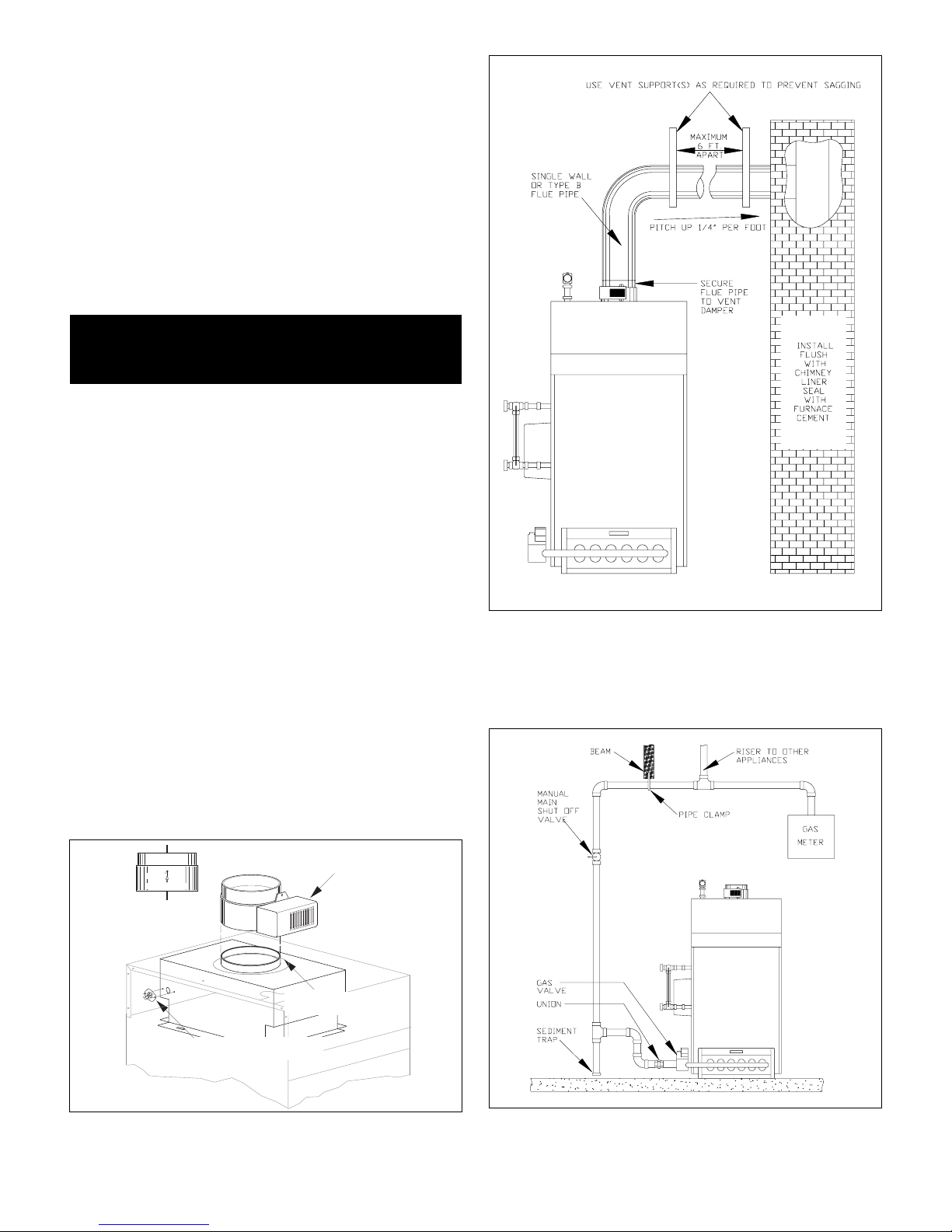
7
STEP 5: INSTALLING/TESTING
GAS PIPING
Connect the gas piping from the meter to the boiler
using a pipe size which will result in a pressure drop of
less than 0.3" W.C. for natural gas or 0.5" W.C. for
propane. See Figure 2.7 for the appropriate gas pipe
sizing and example.
Good piping practices should be followed at all times.
See Figure 2.6 for a typical gas piping arrangement. All
piping must be supported by hangers, not by the boiler
or its accessories.
Install a full-sized sediment trap at the low point in gas
line upstream of gas valve. Install a non-restrictive lubricated plug valve in the gas line close to the boiler. Install
a ground joint union at the gas valve inlet to allow for
servicing. Check local codes and utilities for any special
requirements and procedures.
Pipe joint compound (pipe dope) must be compatible
with the fuel (natural gas or propane) being used.
FIGURE 2.6: TYPICAL GAS PIPING
FIGURE 2.5A: VENTING
ADDITIONAL CHIMNEY REQUIREMENTS
Chimney condition is of paramount importance for a
safe and efficient boiler installation. All installations must
include a chimney inspection by a qualified individual or
agency. Chimney construction materials must be compatible with the fuel being used (see Figure 2.5A).
Particular attention should be paid on all oil-to-gas conversions. Soot may have accumulated in chimney and/or
degraded chimney liner. Most utilities require complete
chimney cleaning. Others may require installation of new
liner, spill switches or other chimney upgrades. Check
with local utility for required safety precautions.
DANGER: A chimney which does not meet modern
safety standards will result in a fire or deadly carbon monoxide poisoning of the building residents.
FIGURE 2.5: ATTACHING VENT DAMPER TO DRAFT
DIVERTER & FLUE PIPE
MAKE SURE MOTOR IS
CLOSED OPEN
FLOW DIRECTION
FLOW DIRECTION
ARROW POINTS UP
(REAR VIEW)
LOCATED ON RIGHT SIDE
MOUNT VENT DAMPER
OVER DRAFT DIVERTER
INSTALL SWITCH IN
OPENING
ON DRAFT DIVERTER
Page 8

Maximum Capacity of Pipe in Cubic Feet of Natural Gas per Hour for Gas Pressures of
0.5 Psig or Less and a Pressure Drop of 0.3 Inch Water Column
(Based on a 0.60 Specific Gravity Gas)
Nominal
Iron Pipe
Size,
Inches
Internal
Diameter,
Inches
Length of Pipe, Feet
10
32
72
132
278
520
1,050
1,600
3,050
4,800
8,500
17,500
20
22
49
92
190
350
730
1,100
2,100
3,300
5,900
12,000
30
18
40
73
152
285
590
890
1,650
2,700
4,700
9,700
40
15
34
63
130
245
500
760
1,450
2,300
4,100
8,300
50
14
30
56
115
215
440
670
1,270
2,000
3,600
7,400
60
12
27
50
105
195
400
600
1,150
1,850
3,250
6,800
70
11
25
46
96
180
370
560
1,500
1,700
3,000
6,200
80
11
23
43
90
170
350
530
990
1,600
2,800
5,800
90
10
22
40
84
160
320
490
930
1,500
2,600
5,400
100
9
21
38
79
150
305
460
870
1,400
2,500
5,100
125
8
18
34
72
130
275
410
780
1,250
2,200
4,500
150
8
17
31
64
120
250
380
710
1,130
2,000
4,100
175
7
15
28
59
110
225
350
650
1,050
1,850
3,800
200
6
14
26
55
100
210
320
610
980
1,700
3,500
1/4"
3/8"
1/2"
3/4"
1"
1-1/4"
1-1/2"
2"
2-1/2"
3"
4"
.326
.493
.622
.824
1.049
1.380
1.610
2.067
2.469
3.026
4.026
Maximum Capacity of Pipe in Thousands of Btu per Hour of Undiluted Liquefied
Petroleum Gases (at 11 Inches Water Column Inlet Pressure)
(Based on a Pressure Drop of 0.5 Inch Water Column)
Nominal
Iron Pipe
Size,
Inches
Length of Pipe, Feet
10
275
567
1071
2205
3307
6221
20
189
393
732
1496
2299
4331
30
152
315
590
1212
1858
3465
40
129
267
504
1039
1559
2992
50
114
237
448
937
1417
2646
60
103
217
409
834
1275
2394
70
96
196
378
771
1180
2205
80
89
185
346
724
1086
2047
90
83
173
322
677
1023
1921
100
78
162
307
630
967
1811
125
69
146
275
567
866
1606
150
63
132
252
511
787
1498
1/2"
3/4"
1"
1-1/4"
1-1/2"
2"
FIGURE 2.7: GAS PIPE SIZING TABLES & EXAMPLE
Example: Boiler Model VS-135B is to be installed. The distance from the existing gas meter to the installation site
is 30 ft. What pipe size must be used? The local utility indicates the heating value of natural gas being supplied is
1000 Btu per cu.ft. Determine cubic feet of gas per hour for above boiler model:
135,000 Btu per hour
= 135 cu.ft. per hour
1000 Btu per cu.ft.
1. Find 30 ft. in upper portion of the table for natural gas under "Length of Pipe, Feet" heading.
2. Moving down the column, match required capacity. Higher capacity is acceptable. In our case it is 152 cu.ft.
3. Move to left-hand column "Nominal Iron Pipe Size, Inches," to read required pipe size. In our case it is 1/2".
8
TESTING GAS PIPING
For any pressure testing in excess of 1/2 psi, the boiler
and its individual shutoff valve must be isolated from the
piping system by disconnecting them and capping the
outlet(s). For any pressure testing equal to or less than
1/2 psi, the boiler must be isolated from the piping system by closing its manual shutoff valve.
Minimum pressure required at the gas valve inlet is 5"
W.C. for natural gas and 11" W.C. for propane. Maximum pressure allowable at the gas valve inlet is 12"
W.C. If the gas pressure is above these limits, a pressure regulator must be installed. If the gas pressure is
DANGER: Before placing gas piping into service,
carefully test it to assure every joint is gas tight.
Bubble test all joints with a soap solution. NEVER
TEST WITH AN OPEN FLAME AS FIRE OR EXPLOSION WILL RESULT.
Page 9
9
All electrical and control wiring must be installed in
accordance with the codes listed in Section 1 of this
manual. Follow the wiring diagram for your particular
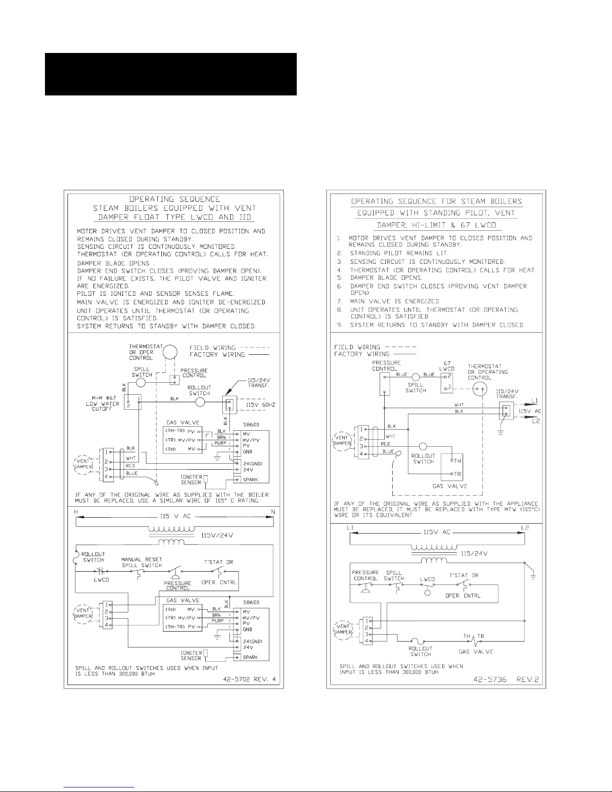
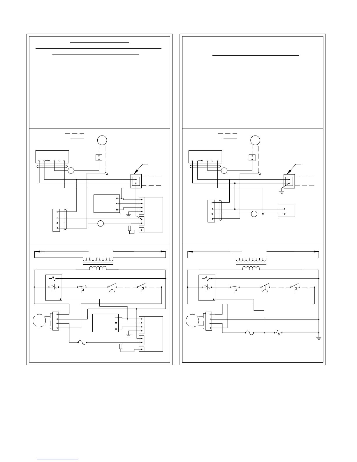
installation as shown in Figures 2.8, 2.9, 2.10 and 2.11.
For vent damper-equipped models, connect thermostat
to blue leads (see Figure 2.4).
NOTE: If any of original wire supplied with boiler
must be replaced, use similar wire of 105 C rating.
Otherwise, insulation may melt or degrade, exposing bare wire.
NOTE: Boiler transformer must not be used to
power external accessories (i.e., zone valves,
relays, etc.) Otherwise, transformer will be overloaded and burn out.
FIGURE 2.8: WIRING DIAGRAM & OPERATION
SEQUENCE FOR BOILERS EQUIPPED WITH INTERMITTENT PILOT, VENT DAMPER & M & M #67 LOW
WATER CUT-OFF
FIGURE 2.9: WIRING DIAGRAM & OPERATION
SEQUENCE FOR BOILERS EQUIPPED WITH INTERMITTENT PILOT, VENT DAMPER & M & M #67 LOW
WATER CUT-OFF
STEP 6: WIRING BOILER
WARNING: Turn off electrical power supply before
servicing. Contact with live electric components
can cause electric shock or death.
Page 10
10
FIGURE 2.10: WIRING DIAGRAM & OPERATION
SEQUENCE FOR BOILERS EQUIPPED WITH
INTERMITTENT PILOT, VENT DAMPER &
400 SERIES LWCO
FIGURE 2.11: WIRING DIAGRAM & OPERATION
SEQUENCE FOR BOILERS EQUIPPED WITH
STANDING PILOT, VENT DAMPER & 400 SERIES
PS804 LWCO
BURNER
T'STAT OR
OPER. CNTRL
SPILL AND ROLLOUT SWITCHES
ON 3 THRU 6 SECTION ONLY
DAMPER
5
2
VENT
1
4
SENSOR
PRESSURE
CONTROL
MV/PV
GAS VALVE
IGNITER
ROLLOUT
SWITCH
(TR)
(TH-TR)
SPILL SWITCH
(TH)
PV
MV
BLK
WHT
BLUE
RED
IF ANY OF THE ORIGINAL WIRE AS SUPPLIED WITH THE BOILER
MUST BE REPLACED, USE A SIMILAR WIRE OF 105∞ C RATING.
H
DAMPER
VENT
5
2
4
1
115 V AC
115V/24V
(TH-TR)
ROLLOUT
GAS VALVE
MV/PV
SWITCH
(TR)
(TH)
SENSOR
IGNITER
PV
BLK
WHT
RED
MV
WHT
WHT
SPARK
60393 REV.2
24(GND)
24V
MV/PV
GND
PV
S8600
MV
N
PV
SPARK
24V
24(GND)
GND
115V 60HZ
S8600
MV/PV
MV
STEAM BOILERS EQUIPPED WITH VENT DAMPER,
1. MOTOR DRIVES VENT DAMPER TO CLOSED POSITION AND
3. THERMOSTAT (OR OPERATING CONTROL) CALLS FOR HEAT.
5. DAMPER END SWITCH CLOSES (PROVING DAMPER OPEN).
6. IF NO FAILURE EXISTS, THE PILOT VALVE AND IGNITER
8. MAIN VALVE IS ENERGIZED AND IGNITER DE-ENERGIZED.
10. SYSTEM RETURNS TO STANDBY WITH DAMPER CLOSED.
CG-400 SERIES LWCO AND IID
REMAINS CLOSED DURING STANDBY.
2. SENSING CIRCUIT IS CONTINUOUSLY MONITORED.
4. DAMPER BLADE OPENS .
7. PILOT IS IGNITED AND SENSOR SENSES FLAME.
9. UNIT OPERATES UNTIL THERMOSTAT (OR OPERATING
CONTROL) IS SATISFIED.
FIELD WIRING
FACTORY WIRING
LOW WATER
CUTOFF
ARE ENERGIZED.
CONTROL
SWITCH
SPILL
BLUE
BLK
PRESSURE
THERMOSTAT
OR OPER.
CONTROL
OPERATING SEQUENCE
115/24V
TRANSF.
LWCO
(H)
1
(B)
P2
(N)
2
P2
(B)
(N)
2
P1
(H)
1
A
BUR
NER
BLK
BURNER
8. UNIT OPERATES UNTIL THERMOSTAT (OR OPERATING
9. SYSTEM RETURNS TO STANDBY WITH DAMPER CLOSED.
6. DAMPER END SWITCH CLOSES (PROVING DAMPER OPEN).
4. THERMOSTAT (OR OPERATING CONTROL) CALLS FOR HEAT.
1. MOTOR DRIVES VENT DAMPER TO CLOSED POSITION AND
115V/24V
MUST BE REPLACED, USE A SIMILAR WIRE OF 105∞ C RATING.
IF ANY OF THE ORIGINAL WIRE AS SUPPLIED WITH THE BOILER
OPER. CNTRL
T'STAT OR
BLUE
4
SWITCH
ROLLOUT
DAMPER
2
5
SPILL SWITCH
LWCO
VENT
(H)
1
1
(B)
(N)
P2
H
2
GAS VALVE
CONTROL
PRESSURE
115 V AC
VENT
DAMPER
BLUE
5
4
2
1
WHT
RED
BLK
SWITCH
ROLLOUT
GAS VALVE
(TH)
(TR)
BLK
WHT
PRESSURE
SPILL
SWITCH
CONTROL) IS SATISFIED.
CUTOFF
LOW WATER
(B)
FACTORY WIRING
FIELD WIRING
1
(H)
(N)
2
NER
BUR
AP2
7. MAIN VALVE IS ENERGIZED.
THERMOSTAT
CONTROL
CONTROL
OR OPER.
5. DAMPER BLADE OPENS .
3. SENSING CIRCUIT IS CONTINUOUSLY MONITORED.
REMAINS CLOSED DURING STANDBY.
60392 REV.2
N
115V 60HZ
TRANSF.
115/24V
RED
WHT
EQUIPPED WITH STANDING PILOT, VENT DAMPER
OPERATING SEQUENCE FOR SREAM BOILERS
HI-LIMIT & CG-400 SERIES LWCO
2. STANDING PILOT REMAINS LIT.
P1
NATURAL GAS 3 THRU 7 SECTION.
LP GAS 3 THRU 9 SECTION.
SPILL & ROLLOUT SWITCHES ON 3 THRU 6 SECTION ONLY.
Page 11
11
SECTION 3: START-UP & OPERATION
SEQUENCE OF OPERATION
For sequence of operation of the particular boiler being
installed, refer to Figures 2.8, 2.9, 2.10 AND 2.11 in
Section 2 of this manual.
Spill and rollout switches are mounted on all VS-B boilers (U.S. only) manufactured after December 31, 1990.
For boilers with a spill switch, the switch detects the
escape of combustion products through the draft diverter relief opening and interrupts the power to the gas
valve preventing unsafe boiler operation. Escape of flue
products could be caused by a blocked or collapsed
chimney or inadequate chimney draft. This is a manual
reset-type device and can be reactivated by depressing
the spill switch reset button mounted in the front of the
boiler’s draft diverter (see Figure 2.1 for switch location).
For boilers with a flame rollout switch, the switch prevents flame rollout from the boiler combustion chamber,
caused by blocked boiler flue passageways, by interrupting power to the gas valve to prevent unsafe boiler operation. This is a single use device and must be replaced if
it is tripped (see Figure 2.1 for switch location). Flue passages must be inspected by a qualified installer if this
problem occurs, prior to switch replacement.
PRIOR TO START-UP
Fill system with water until the water level indicator
(sight glass) is approximately 2/3 full. This water level is
23" from the surface on which the boiler sits.
SYSTEM START-UP & ADJUSTMENTS
Safe lighting and other performance criteria were met
with the gas manifold and control assembly provided on
the boiler when the boiler underwent tests specified in
ANSI Z21.13-LATEST EDITION.
1. Check combination gas valve on boiler and make
sure it is in the OFF position.
2. For vent damper-equipped models, with the thermostat set to call for heat, observe that vent damper position indicator rotates to the open position (see Figure
2.5). Damper must be in the open position when appliance main burner is operating.
a. After damper opens, spark should appear at the
pilot ignition electrodes.
b. Set thermostat to no longer call for heat. Spark
should stop. Observe that damper position indicator
rotates to the closed position.
c. Set thermostat to call for heat.
3. Light the boiler. For Model VS-B boilers with intermittent pilot, see lighting instruction on Page 15.
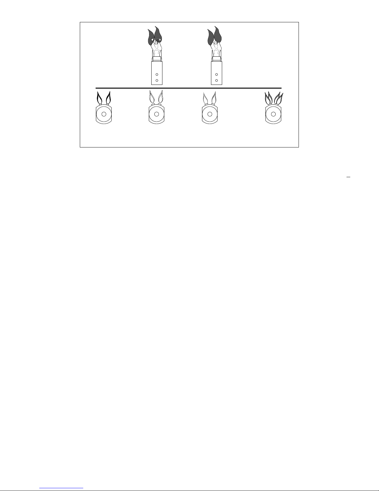
4. Observe pilot and main burner flame (see Figure 3.2).
All burner ports should be ignited and burn with a
steady blue flame.
CAUTION: Never leave the job with yellow burning
flames. This condition indicated poor combustion
and will quickly carbonize the boiler, reducing efficiency and boiler life. It may also be an indication of
improper venting or combustion air supply. If
unable to adjust flame properly, consult your local
utility.
5. Boilers are shipped from the factory with the primary
air shutters on the main burner wide open. It is recommended these air shutters be left in the wide open posi-
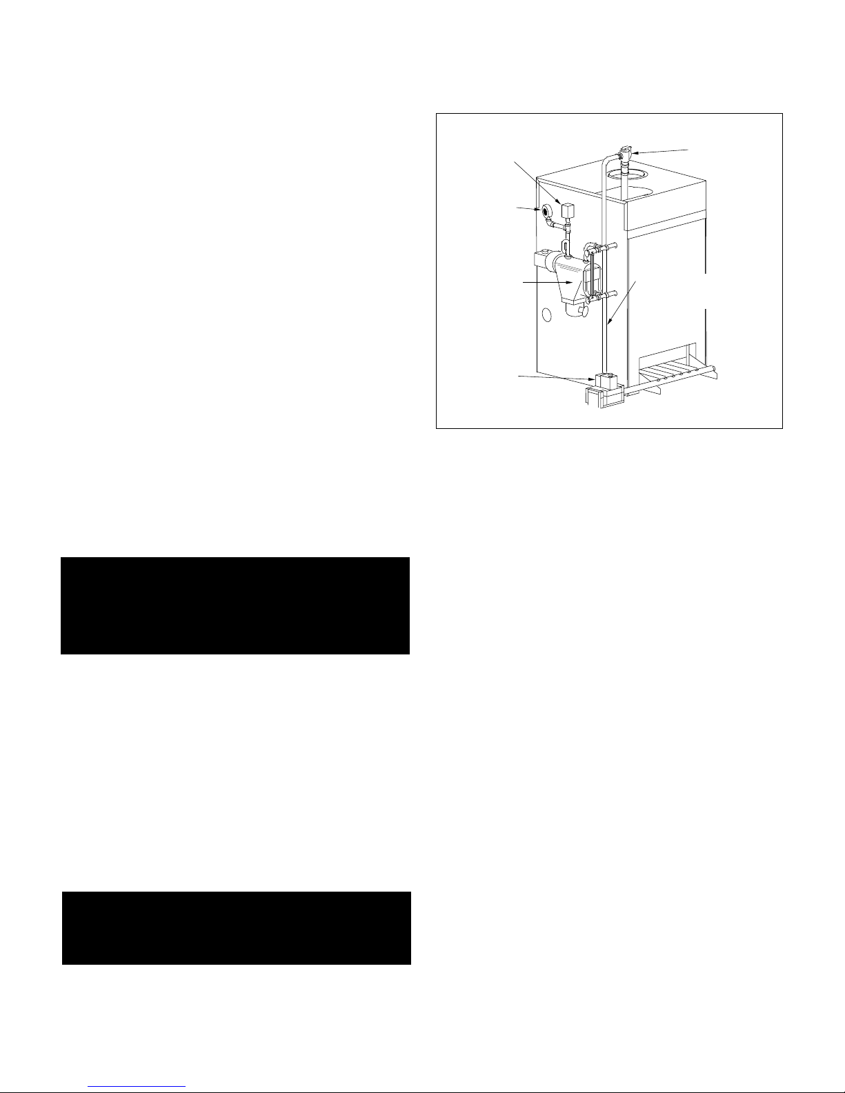
FIGURE 3.1: STEAM CONTROL ARRANGEMENT
WARNING: If boiler cannot be restored to normal
operation after re-setting of spill switch, or if flame
rollout switch has tripped, do not attempt to put the
boiler in operation. Immediately contact a qualified
service professional.
WARNING: Keep boiler area clear and free from
combustible materials, gasoline and other
flammable vapors and liquids. Otherwise fire or
explosion may result.
PRESSURE
RELIEF VALVE
OPTIONAL
FLOAT
LOW WATER
CUT OFF
PRESSURE
CONTROL
PRESSURE
GAUGE
GAS VALVE
PRESSURE RELIEF
VALVE DISCHARGE
PIPING
Page 12
tion unless there is lifting of the flame above the burner
ports. If there is lifting, the air shutters should be gradually closed until the lifting is eliminated. It may also be
necessary to adjust the primary air shutters if the input
rate is reduced by a change in the orifices.
6. After burner has been in operation for about 10 minutes, check gas input rate to boiler as follows:
a. Make sure all appliances served by the meter are
turned off during timing of gas input rate to the boiler.
b. Measure the time in seconds that it takes for the
boiler to use 10 cubic feet of gas. Divide 36,000 by
the number of seconds (this is the number of cubic
feet of gas used per hour). Multiply this figure by the
heating value of the gas to obtain Btu input per hour.
Example: A VS-110B boiler takes 5 minutes, 27 seconds to use 10 cubic feet of natural gas. The local utility
indicated the heating value of the natural gas being supplied is 1000 Btu/cu ft. Therefore:
5 minutes, 27 seconds = 327 seconds.
36,000
X 1000 = 110,000 Btu/hr
327
Therefore, the boiler input is correct.
NOTE: Before calculating the input of the heating
equipment, obtain the heating value of the gas from
the local utility.
7. If input needs to be corrected, adjust combination gas
valve pressure regulator. (Regulator is factory set at 31/2" W.C. for natural gas and 10" W.C. for propane.)
Turn adjusting screw clockwise to increase gas flow
(increase input). Turn adjusting screw counterclockwise
to decrease gas flow (decrease input). In no case
should final manifold pressure setting vary more than +
.3" from factory-set pressures. If rated input cannot be
obtained with adjustment, gas supply pressure or orifice
size may be cause. Consult local utility and Hydrotherm.
8. Gas burner orifices supplied with boiler have been
carefully designed to provide correct gas input rate for
most gas conditions typically found in the U.S. Occasionally, however, local gas characteristics may not allow
unit to be properly adjusted for input. If this is the case,
local utility or Hydrotherm may recommend orifices be
changed. When changing orifices follow the procedures
detailed in Section 4 of this manual.
9. Start and stop burners several times by raising and
lowering the thermostat setting.
10. After boiler has been firing long enough to raise boiler pressure above minimum setting of the primary pressuretol limit, check limit by turning its setting from maximum to minimum setting. This should turn boiler off.
Return limit to desired setting.
11. Check boiler safety shutoff controls.
a. For boilers with standing pilot, with boiler firing, disconnect thermocouple lead from the valve. The valve
should close.
b. For boilers with intermittent pilot, with boiler firing,
disconnect wire connected to the "PV" terminal on the
Honeywell S8600 control. The gas valve should
close.
12. On initial start-up and prior to each heating season,
boiler must be cleaned with a commercially available
steam boiler cleaner (see "Steam Boiler Cleaning
Instructions" in Section 4 of this manual).
12
FIGURE 3.2: BURNER FLAME COMPARISON/PILOT FLAME
Q345
INTERMITTENT
IGNITION PILOT
MODELS
NORMAL PILOT
FLAME
Q314A/Q309A
CONSTANT PILOT
MODELS
NORMAL
(HARD FLAME)
LIFTING
(TOO MUCH AIR)
MAIN BURNER FLAMES
YELLOW TIPPING
(MARGINAL)
YELLOW FLAME
(TOO LITTLE AIR)
Page 13
13
WARNING:
If you do not follow these instructions exactly, a fire or explosion may result with property
damage, personal injury, or loss of life.
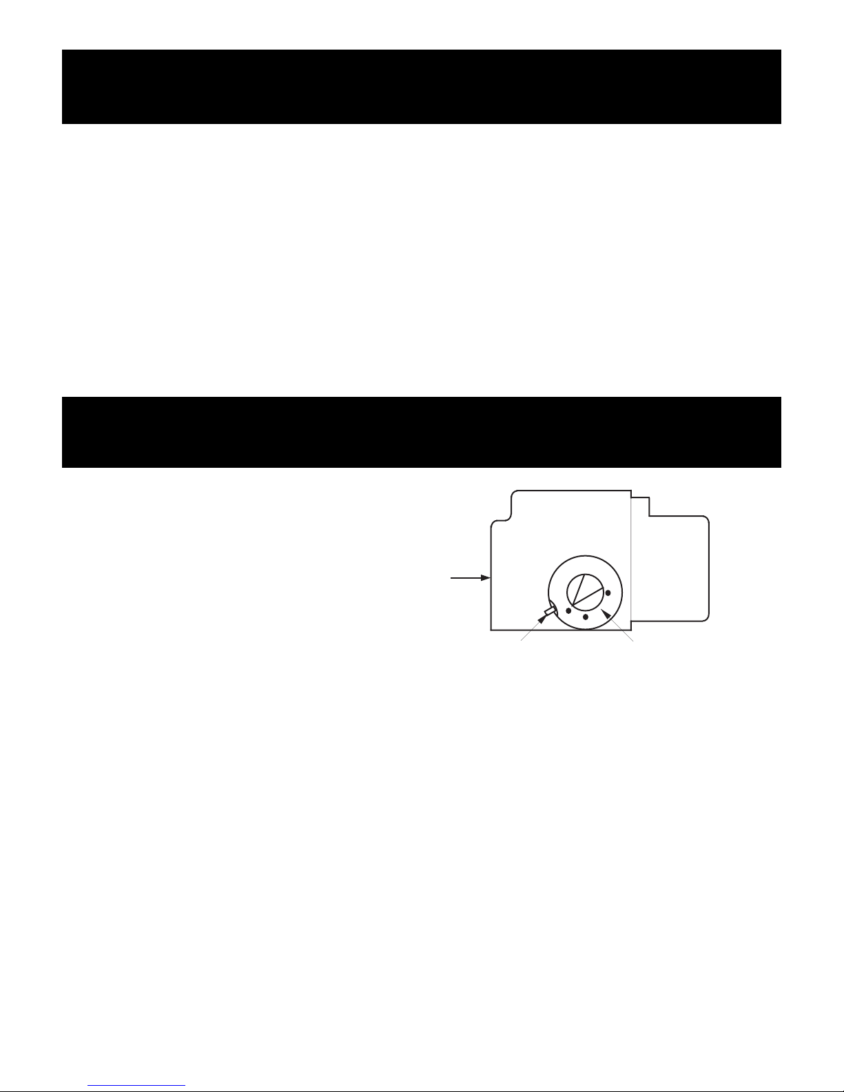
OPERATING INSTRUCTIONS
Honeywell VR8200
Natural or Propane Gas
A. Before Operating smell all around the appliance area
for gas. Be sure to smell next to the floor because
some gas is heavier than air and will settle on the
floor.
What to do if you smell gas:
• Do not try to light any appliance.
• Do not touch any electrical switch. Do not use any
phone in your building.
• Immediately call your gas supplier from a neighbor's phone. Follow the gas supplier's instructions.
• If you cannot reach your gas supplier, call the fire
department.
B. Use only your hand to push in or turn the gas control
knob, never use tools. If the knob will not push in or
turn by hand, don't try to repair it; call a qualified service technician. Force or attempted repair may result
in a fire or explosion.
C. Do not use this appliance if any part has been under
water. Immediately call a qualified service technician
to inspect the appliance and to replace any part of
the control system and any gas control which has
been under water.
1. STOP! Read the safety information above.
2. Set the thermostat to lowest setting.
3. Turn off all electric power to the appliance.
4. Remove control access panel (if applicable).
5. Rotate gas control knob clockwise to "OFF".
6. Wait five (5) minutes to clear out any gas. Then
smell for gas, including near the floor. If you smell
gas, STOP! Follow "A" in the safety information
above. If you don't smell gas, go to next step.
7. Remove the pilot access panel located below and
behind the gas control unit (if applicable).
8. Find pilot — follow metal tube from gas control. The
pilot is between the two burner tubes behind the
pilot access panel (if applicable).
9. Turn gas control knob counterclockwise to "PILOT".
10. Push down and hold the red button next to the control knob. Immediately light the pilot with a match.
Continue to hold the red button down for about one
(1) minute after the pilot is lit. Release button and it
will pop back up. Pilot should remain lit. If it goes
out, repeat steps 5 through 10.
• If button does not pop up when released, stop
and immediately call your service technician or
gas supplier.
• If the pilot will not stay lit after several tries, turn
the gas control knob to "OFF" and call your
service technician or gas supplier.
11. Replace pilot access panel.
12. Turn gas control knob counterclockwise to "ON".
13. Replace control access panel (if applicable).
14. Turn on all electric power to the appliance.
15. Set thermostat to desired setting.
CONTINUOUS PILOT – HONEYWELL VR8200
GAS
INLET
RESET BUTTON
OFF
ON
PILOT
GAS CONTROL KNOB
SHOWN IN "OFF" POSITION
Page 14
14
1. Set the thermostat to lowest setting.
2. Turn off all electric power to the appliance if service is
to be performed.
3. Turn gas control knob counterclockwise to “OFF” Do
not force.
OPERATING INSTRUCTIONS
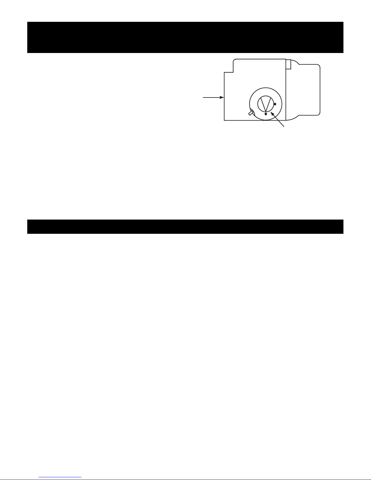
Intermittent Pilot – Honeywell VR8204
Natural or Propane Gas
TO TURN OFF APPLIANCE
1. STOP! Read the safety information on page 13.
2. Set the thermostat to lowest setting.
3. Turn off all electric power to the appliance.
4. This appliance is equipped with an ignition device
which automatically lights the pilot. Do not try to
light the pilot by hand.
5. Remove control access panel (if applicable).
6. Rotate gas control knob clockwise to "OFF".
7. Wait five (5) minutes to clear out any gas. Then
smell for gas, including near the floor. If you then
smell gas STOP! Follow "A" on page 13. If you don't
smell gas, go to next step.
8. Turn gas control knob counterclockwise to "ON".
9. Replace control access panel (if applicable).
10. Turn on all electric power to the appliance.
11. Set thermostat to desired setting.
12. If the appliance will not operate, follow the instructions "To Turn Off Appliance" and call your service
technician or gas supplier.
INTERMITTENT PILOT – HONEYWELL VR8204
INLET
GAS
ON
OFF
GAS CONTROL KNOB
SHOWN IN "OFF" POSITION
Page 15

SECTION 4: MAINTENANCE
This boiler has been designed to provide years of trouble
free performance in normal installations. Examination by
the homeowner at the beginning of each heating season,
and in mid-heating season, should assure continued good
performance. In addition, the boiler should be examined by
a qualified service professional at least once every year.
NOTE: Do not draw water from heating system for
cleaning. Minerals in the water can build up on the
heat transfer surfaces and cause overheating and
subsequent failure of the cast iron sections.
NOTE: To reduce the risk of fouling, the low water cutoff should be blown down at least once a week during
heating season.
BEFORE EACH HEATING SEASON
1. Remove and inspect draft diverter and smoke pipe
(connecting draft diverter to chimney or vent) for obstructions, soot accumulation, rust or corrosion. Clean and
replace as necessary. Check tightness of joints; seal all
joints where necessary.
2. Check boiler flue passageways in the boiler sections for
any blockage or soot accumulation. Remove draft diverter,
jacket top and flue collector. Using a flashlight, examine all
flue passageways.
a. If passageways are free of soot and obstructions,
replace collector and seal with furnace cement.
b. If passageways need cleaning, remove flueway baffles
and burners as described in paragraph 3 below. Insert
long-handle bristle flue brush down between section
tubes and upward through sections from combustion
chamber in both diagonal directions to remove carbon
from finned surfaces. Vacuum debris. Replace the draft
diverter and seal with furnace cement.
c. Reinstall jacket top panel and draft diverter.
3. Check and clean burner assembly. Remove burner
access panel. Lift burners up and to rear until burners are
disengaged from orifices. Brush top of burners with soft
bristle brush and blow out with air or vacuum.
4. Check gas manifold for proper position and reassemble
burners to the manifold. Line up holes in burners with the
orifices, and slide assembly back into position. BE SURE
TO REINSTALL BURNERS WITH BURNER PORTS ON
THE TOP SURFACE (UPRIGHT).
5. When a low water cut-off has been utilized, follow the
manufacturer’s maintenance instructions. As a minimum,
Inspect the probe and test the operation of electronic controls at least once a year. Remove, clean and inspect the
probe. Float type controls should be flushed once a month
during heating season. If the LWCO fails to operate properly it must be replaced.
6. Follow "System Start-Up & Adjustments" procedures in
Section 3 of this manual.
STEAM BOILER CLEANING INSTRUCTIONS
The following procedures must be followed on initial startup and if the presence of sediment, sludge or impurities
hamper proper boiler operations.
1. With gate valves closed on supply and return lines, start
burner and allow boiler to become pressurized so that the
pressuretol may be adjusted and set for limit cut-off
desired (normally about 3 psi). Turn off burner and allow
pressure to drop to 0 psi., then proceed with the following
cleaning procedure.
2. Remove the pressure relief valve.
3. Add caustic soda (lewis lye) through this opening at the
rate of one pound per thousand square feet of radiation
capacity. Scout, Squirk or similar steam boiler cleaners
may be used instead of lye. Trisodium phosphate (1/4#) is
also an excellent cleaner.
4. Provide pipe connection (full size) from pressure relief
valve opening to a convenient drain to serve as a vent.
5. Fill the boiler with a manual fill valve until water starts to
trickle from this pipe.
DANGER:To avoid fire and explosion hazards: Do
not store anything against the boiler or allow dirt or
debris to accumulate in the area immediately surrounding the boiler. Keep boiler area clear and free
from combustible materials, gasoline and other
flammable vapors and liquids. Lint, paper or rags
must not be allowed to accumulate near the burners. Do not place clothing on boiler casing to dry.
15
WARNING: Improper installation, adjustment, alteration, service or maintenance can cause property
damage, personal injury exposure to hazardous
materials or loss of life. Installation and service
must be performed by a qualified installer, service
agency or the gas supplier who must read and follow the supplied instructions before installing, servicing or removing this boiler, This boiler contains
crystalline silica materials that have been identified as carcinogenic or possibly carcinogenic to
humans when inhaled.
Page 16

16
6. Fire boiler at sufficient rate to generate and maintain
steam. Entrain water and impurities will then discharge
(with steam) from open vent. Add water as necessary so
that the low water cutoff does not shut off burner.
7. Continue this process for a minimum of one hour. The
process should continue until the steam is dry (no water
coming from the vent when the water in the gauge glass is
at a normal level, approximately 2/3 full). The time required
could vary up to 3 hours.
8. Turn gas valve to off position. While boiler is still hot,
drain completely through boiler drain. Make sure that all
low points in the return line are also completely drained.
These areas could trap chemicals and dirt.
9. Close boiler drain and refill with clean untreated warm
water. If warm water is not used, fill very slowly so as not
to crack boiler sections. Fill until water overflows through
vent pipe and runs clear.
10. Completely drain boiler again.Refill with clean
untreated water to normal level.
11. Remove vent drain piping and reinstall pressure relief
valve. Open gate valves on supply and return lines. Turn
on burner. System is now ready to operate.
HOW TO CHANGE ORIFICES
1. Shut off power supply and gas supply to the boiler.
2. Remove burner access panel. Lift burners up and to
rear until burners are disengaged from orifices.
3. Check orifices for proper drill size. Size is stamped onto
the body of the brass orifice (see Figure 4.1). Size can
also be checked by using a pin gauge.
4. All orifices are screwed into the manifold and may be
removed by using a 5/8" wrench or socket.
5. Reverse procedures above to install orifices and
burners. BE SURE TO REINSTALL BURNERS WITH
BURNER PORTS ON TOP SURFACE (UPRIGHT).
HEATING SYSTEM PROBLEMS & CAUSES
No Heat
1. Blown fuse or circuit breaker.
2. Switch turned off.
3. Pilot outage
4. IID system malfunction.
5. Flue damper not open.
6. Water level too low.
Insufficient Heat
1. Incorrect thermostat anticipator setting.
2. Low pressuretol setting.
3. Boiler undersized or underfired.
4. Insufficient radiation.
Odor, Excessive Moisture In Building
1. Leak in piping.
2. Carbon build-up in flueways.
3. Blocked chimney.
Yellow Flame, Carbon Build-Up
1. Unit overfired.
2. Air shutter misadjustment.
3. Wrong orifices.
4. Burning in burner mixing tube.
Noise
1. Ignition or ignition noise due to incorrect air shutter
adjustment.
2. Whistle due to burr on orifices.
3. Burner "fluteings" due to air shutter opening too wide.
Overheating
1. Wrong thermostat anticipator setting.
2. Bad thermostat location.
3. Bad thermostat.
FIGURE 4.1: VS-B ORIFICE SIZES
Boiler
Model
VS-85B VS-110B VS-135B VS-165B
(1) Nat. Gas
Drill Size
(2) Prop. Gas
Drill Size
41 41 37 38
53 53 52 52
CAUTION: Label all wires prior to disconnection
when servicing controls. Wiring errors can cause
improper and dangerous operation.
Verify proper operation after servicing.
Page 17
17
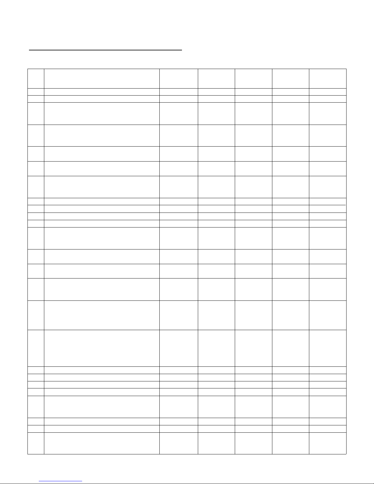
1 Side Panel - L.H. - Base Ass'y BM-8055 1111
2 Side Panel - R.H. - Base Ass'y BM-8053 1111
3 Rear Panel - Base Ass'y BM-8063 1
Rear Panel - Base Ass'y BM-8064 1 1
Rear Panel - Base Ass'y BM-8065 1
4 Front - Base Ass'y BM-8056 1
Frontl - Base Ass'y BM-8057 1 1
Frontl - Base Ass'y BM-8058 1
6 Manifold Bracket - L.H. - Side 03-7345 1 1 1
Manifold Bracket - L.H. - Side 03-7347 1
7 Manifold Bracket - R.H. - Side 03-7346 1 1 1
Manifold Bracket - R.H. - Side 03-7348 1
8 Burner Support Bracket 03-7366 1
Burner Support Bracket 03-7368 1 1
Burner Support Bracket 03-7369 1
9 Jacket Support Bracket - L.H. - Side 03-7135 1111
10 Jacket Support Bracket - R.H. - Side 03-7136 1111
11 Burner 03-7114 2334
12 Burner w/Pilot Bracket 03-7118 1111
13 Base Door Ass'y 03-7517-1 1
Base Door Ass'y 03-7518-1 1 1
Base Door Ass'y 03-7519-1 1
14 Igniter Sensor - N.G. - Q345 62-3668 1111
Igniter Sensor - L.P. - Q345 BM-9613 1111
– Pilot Orifice - N.G. (BCR18) 62-3326 1111
Pilot Orifice - L.P. (BBR10) 62-3327 1111
15 Manifold 24-1411 1
Manifold 24-1413 1 1
Manifold 24-1414 1
16 Gas Valve - 24 V Nat. Gas 02-1543 1111
VR8204 H 1006
Gas Valve - 24 V L.P. Gas 02-1546 1111
VR8204 H 1014
17 Burner Orifice - #37 (N.G.) 25-1121 4
Burner Orifice - #38 (N.G.) 25-1137 5
Burner Orifice - # 41 (N.G.) 25-1134 3 4
Burner Orifice - # 52(L.P) 25-1129 4 5
Burner Orifice - # 53 (L.P.) 25-1128 3 4
18 Hold Down Bracket 03-7296 4444
19 Section, Rear BM-9677 1111
20 Section, Intermediate 01-1703 1223
21 Section, Front (No Coil Opening) BM-9672 1111
22 Abs. Unit Ass'y BM-3182 1
Abs. Unit Ass'y BM-3183 1 1
Abs. Unit Ass'y BM-3184 1
23 Port Seal - 5" 59-2004 2334
24 Port Seal - 2" 59-2003 2334
25 3/8 - 16 X 8 1/2" Lg. Tie Rod 44-1018 1
3/8 - 16 X 12" Lg. Tie Rod 44-1010 1 1
3/8 - 16 X 15 1/2" Lg. Tie Rod 44-1019 1
REF
NO. NAME OF PART PART NO. VS-85B VS-110B VS-135B VS-165B
MODEL VS-A SERIES REPLACEMENT PARTS LIST
ORDERING INFORMATION: When ordering parts, provide
model and serial number shown on unit rating plate as well
as part number and name as shown in parts list. Parts may
be obtained from your local Hydrotherm heating contractor.
VS-B SERIES
REPLACEMENT PARTS LIST
Page 18

26 3/8 - 16 X 12" Lg. Tie Rod 44-1010 3
3/8 - 16 X 15 1/2" Lg. Tie Rod 44-1019 3 3
3/8 - 16 X 18 1/2" Lg. Tie Rod 44-1063 3
27 3/8 - 16 Hex. Nut 57-2601 7777
28 3/8 Flat Washer 57-4602 7777
29 Pipe Plug - 2" Sq. Hd. 56-4552 1111
30 Pipe Plug - 1" Sq. Hd. 56-4601 1111
31 Bushing - 3" X 2" 56-4217 1111
32 Flue Baffle BM-8080 2334
33 Nipple - 1/2" X 4" (Brass) 53-1085 2222
34 Low Water Cut-Off (CG400) 21-2018 1111
35 Pigtail - 1/4" 56-5400 1111
36 Tee - 1/4" 56-1000 1111
37 Nipple - 1/4" X Close 53-1026 1111
38 Pressuretrol 02-4807 1111
39 Tee - 1/2" X 1/2" X 1/4" 56-1351 1111
40 Press. Gauge 20-3002 1111
41 Water Gauge 20-2005 1111
42 Nipple - 3/4" X 14" 53-1136 1111
43 Coupling - 3/4" 56-5001 1111
44 Pressure Relief Valve - 15 P.S.I. 22-1401 1111
45 Draft Diverter BM-8081 1
Draft Diverter BM-8082 1
Draft Diverter BM-8083 1
Draft Diverter BM-8084 1
46 5/16 - 18 X 1 1/4 Lg. Weld Screw 57-5908 4444
47 5/16 - 18 Hex. Nut 57-2602 4444
48 Transformer - 115/24V 26-3005 1111
49 Junction Box - 4" X 4" 58-1800 1111
- Silicone Sealant 11 oz. (Not Shown) 10-6627 1111
- Fiberglass Rope - 5ft. (Not Shown) 10-6651 1111
18
REF
NO. NAME OF PART PART NO. VS-85B VS-110B VS-135B VS-165B
Page 19
ALTERNATE LOW WATER CUT-OFF AND CONNECTING FITTINGS (SEE FIGURE 2)
58 Low Water Cut-Off (Hon. RW700A) BM-1223 1111
59 Water Gauge 20-2005 1111
60 Nipple - 1/2" X 3 1/2" (Brass) 53-1107 1111
61 Coupling - 1/2" (Brass) 56-5012 1111
62 Tee-1/2" X 1/2" X 1/4" (Brass) 56-1352 1111
63 Nipple - 1/2" X 4" (Brass) 53-1106 1111
ALTERNATE LOW WATER CUT-OFF/FEEDER AND CONNECTING FITTINGS (SEE FIGURE 2)
64 Low Water Cut-Off & Feeder (M-M#47-2) 21-2002 1111
65 Water Gauge 20-2005 1111
66 Tail Piece 21-2300 1111
67 Bushing - 1/2" X 1/4" 56-4201 1111
68 Bushing - 2" X 1/2" 56-4208 1111
69 Coupling - 1/2" (Brass) 56-5012 2222
70 Union - 1/2" 56-4800 1111
71 Elbow - 1/2" 56-3303 2222
72 Nipple - 1/2'" X 2" 53-1078 1111
73 Nipple - 1/2" X 3" (Brass) 53-1111 2222
74 Nipple - 1/2" X Close 53-1076 1111
75 Nipple - 1/2" X 3" 53-1080 2222
PARTS FOR VS-B JACKET ASSEMBLY (SEE FIGURE 3)
- Jacket-Complete BM-2648 1
Jacket-Complete BM-2649 1 1
Jacket-Complete BM-2650 1
58 Front Panel BM-2651 1111
59 Rear Panel BM-2652 1111
60 Side Panel-L.H. BM-2653 1
Side Panel-L.H. BM-2654 1 1
Side Panel-L.H. BM-2655 1
61 Side Panel-R.H. BM-2656 1
Side Panel-R.H. BM-2657 1 1
Side Panel - R.H. BM-2658 1
62 Top Panel BM-2659 1
Top Panel BM-2660 1 1
Top Panel BM-2661 1
64 Ignition Control S8600M BM-8143 1111
65 Vent Damper W/Harness Ass'y. 02-5865 1
Vent Damper W/Harness Ass'y. 02-5866 1 1
Vent Damper W/Harness Ass'y. 02-5854 1
66 Spill Switch (Manual Reset) 58-2524 1111
67 Rollout Switch (Thermal Fuse) 58-1895 1111
Cable Bracket - Not Shown 03-7144 1111
19
REF
NO. NAME OF PART PART NO. VS-85B VS-110B VS-135B VS-165B
Page 20
17 Pilot Ass'y NG-Q314ALB, Q309A, BCR18 BM-8072 1111
Pilot Ass'y LP-Q314ALB, Q309A, BBR10 BM-8073 1111
18 Pilot Orifice NG (BCR18) 62-3326 1111
Pilot Orifice LP (BBR10) 62-3327 1111
19 Thermocouple Q309A 04-1302 1 1 1
Thermocouple Q309A (3 FT) 04-1306 1
20 Pilot Line w/ Fittings BM-8078 1 1 1
Pilot Line w/ Fitting BM-8079 1
22 Gas Valve - NG VR8200H1129 02-1540 1111
Gas Valve - LP VR8200H1137 02-1541 1111
56 Transformer 115/24V 20VA 26-3005 1111
REF
NO. NAME OF PART PART NO. VS-85B VS-110B VS-135B VS-165B
PARTS FOR STANDING PILOT
20
Page 21
21
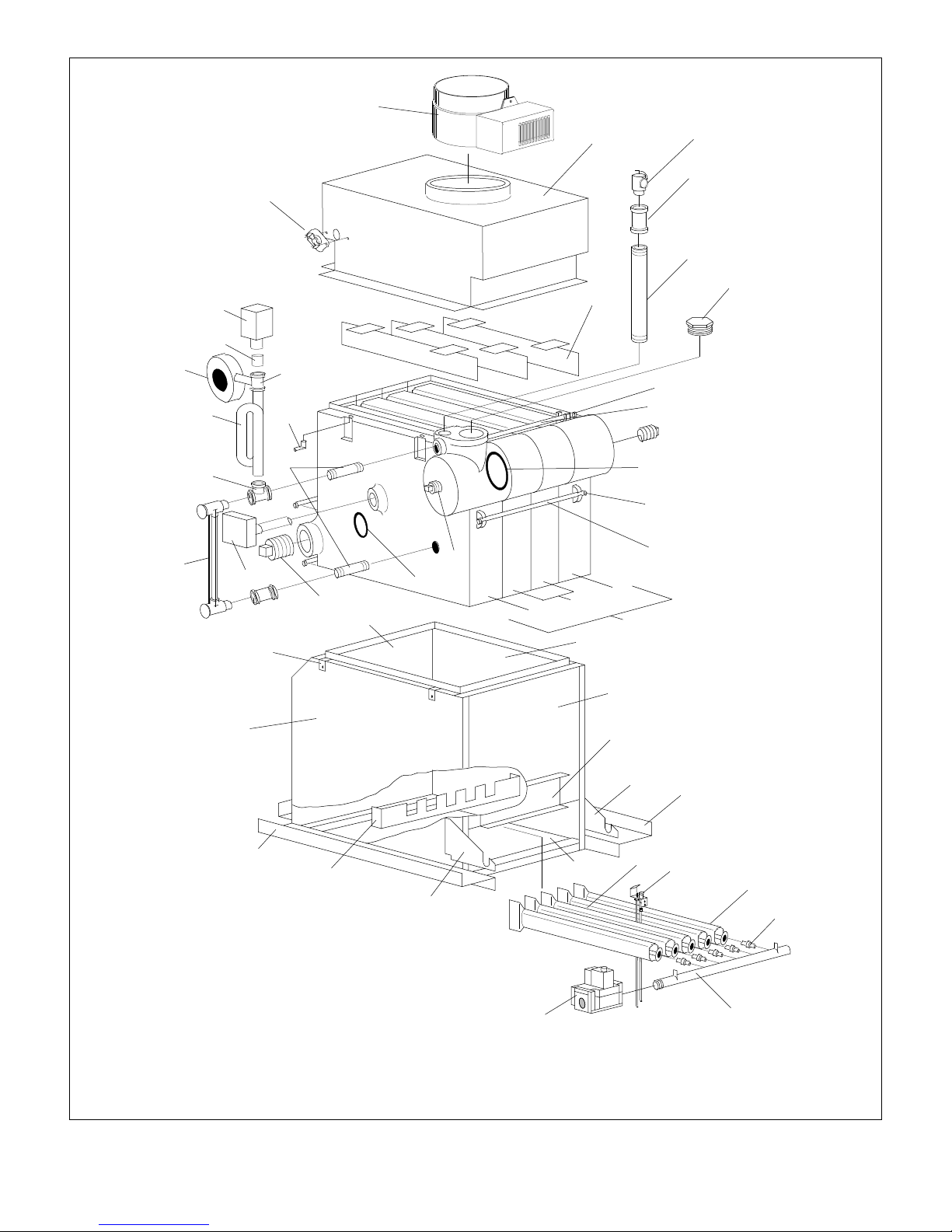
FIGURE 1: VS-B GENERAL ASSEMBLY
66
65
44
45
43
42
40
41
35
39
38
37
34
1
18
36
46/77
33
29
32
27/28
25
23
27/28
30
24
20
3
21
2
26
19
22
4
13
31
9
8
5
6
16
7
12
10
14
11
17
15
Page 22
22
67
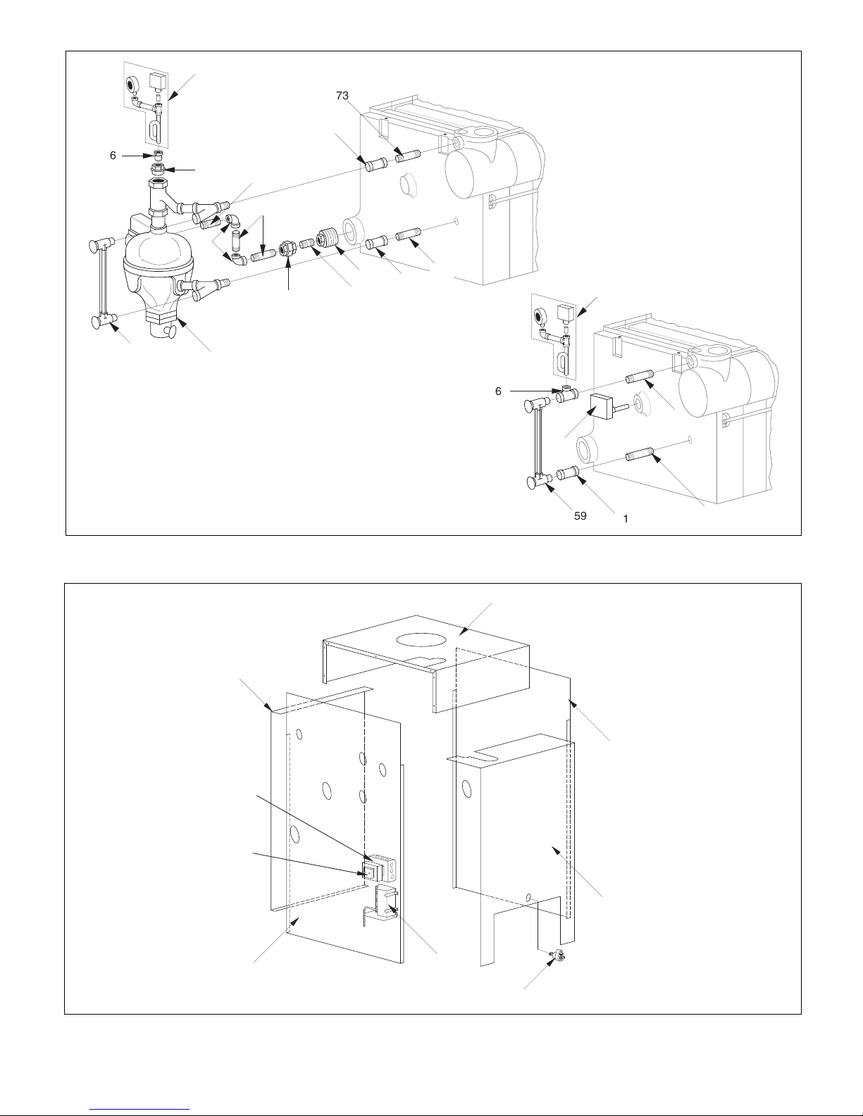
FIGURE 2: LOW WATER CUT-OFF AND FITTINGS
FIGURE 3: JACKET ASSEMBLY
SAME AS IN FIGURE 1
66
71
72
75
73
69
65
68
70
74
McDONNELL MILLER # 47-2
LOW WATER CUT-OFF/FEEDER
64
AND FITTINGS
HONEYWELL RW700A
LOW WATER CUT-OFF
59
73
69
AND FITTINGS
62
62
58
SAME AS IN FIGURE 1
59
61
60
63
49
48
60
61
58
64
67
Page 23

23
NOTES
Page 24

260 NORTH ELM ST. • WESTFIELD, MA 01085 • (413) 564-5515 • FAX (413) 568-9613
5211 CREEKBANK ROAD • MISSISSAUGA, ONTARIO L4W 1R3 • (905) 625-2991 • FAX (905) 625-6610
 Loading...