

HydroTherm VGX 88, VGX 177, VGX 147, VGX 118, VGX 206 Installation And Operation Instructions Manual
...
This manual is intended only for use by a qualified heating installer/technician. Read and follow this manual, all supplements and related
instructional information provided with the boiler. Install, start and service the boiler only in the sequence and methods given in these
instructions. Failure to do so can result in severe personal injury, death or substantial property damage.
Do not use the boiler during construction. Construction dust and particulate, particularly drywall dust, will cause contamination of
the burner, resulting in possible severe personal injury, death or substantial property damage. The boiler can only be operated with a dustfree air supply. Follow the instruction manual procedures to duct air to the boiler air intake. If the boiler has been contaminated by operation
with contaminated air, follow the instruction manual guidelines to clean, repair or replace the boiler if necessary.
Affix these instructions near to the boiler/water heater. Instruct the building owner to retain the instructions for future use by a qualified
service technician, and to follow all guidelines in the User’s Information Manual.
VGX
Gas-fired residental steam
boilers
Models 88-288
Boiler manual
Installation and
operation instructions
VGX2-910
22-VGX2
USING THIS MANUAL 2
A. MANUAL ORGANIZATION . . . . . . . . . . . . . . . . . . . . . . . .2
B. SPECIAL ATTENTION BOXES . . . . . . . . . . . . . . . . . . . . .2
1. PREINSTALLATION 3
A. GENERAL . . . . . . . . . . . . . . . . . . . . . . . . . . . . . . . . . . . . .3
B. CODES & REGULATIONS . . . . . . . . . . . . . . . . . . . . . . . . .3
C. ACCESSIBILITY CLEARANCES . . . . . . . . . . . . . . . . . . . . .3
D. CLEARANCE FROM COMBUSTIBLE
CONSTRUCTION . . . . . . . . . . . . . . . . . . . . . . . . . . . . . . . .3
E. AIR COMBUSTION AND VENTILATION . . . . . . . . . . . . .4
2. BOILER PLACEMENT & ASSEMBLY 7
A. PACKAGED BOILER . . . . . . . . . . . . . . . . . . . . . . . . . . . . .7
3. VENTING 7
A. CHIMNEY OR VENT . . . . . . . . . . . . . . . . . . . . . . . . . . . . .7
B. AUTOMATIC VENT DAMPER
INST ALLATION – GENERAL . . . . . . . . . . . . . . . . . . . . . . .7
C. BOILER REMOVAL FROM COMMON
VENTING SYSTEM . . . . . . . . . . . . . . . . . . . . . . . . . . . . . .8
4. BOILER PIPING 9
A. STEAM BOILER PIPING – SINGLE
BOILER . . . . . . . . . . . . . . . . . . . . . . . . . . . . . . . . . . . . . . .9
B. STEAM BOILER INDIRECT WATER HEATER
PIPING . . . . . . . . . . . . . . . . . . . . . . . . . . . . . . . . . . . . . . .10
5. FUEL PIPING 10
A. INSTALLATION . . . . . . . . . . . . . . . . . . . . . . . . . . . . . . . .10
B. OPERATION . . . . . . . . . . . . . . . . . . . . . . . . . . . . . . . . . . .10
6. CONTROLS & TRIM 12
A. STEAM BOILER CONTROLS & TRIM . . . . . . . . . . . . . . .12
7. ELECTRICAL 13
A. CONNECT SUPPLY WIRING . . . . . . . . . . . . . . . . . . . . . .13
B. INSTALL CONTROL WIRING . . . . . . . . . . . . . . . . . . . . .13
C. WIRING DIAGRAM INDEX . . . . . . . . . . . . . . . . . . . . . . .13
8. BOILER OPERATION 17
A. SYSTEM INSPECTION . . . . . . . . . . . . . . . . . . . . . . . . . .17
B. FILL THE BOILER (STEAM BOILERS) . . . . . . . . . . . . . . .17
C. LIGHTING INSTRUCTIONS . . . . . . . . . . . . . . . . . . . . . . .17
D. PILOT CHECK . . . . . . . . . . . . . . . . . . . . . . . . . . . . . . . . .17
E. MAIN BURNER CHECK . . . . . . . . . . . . . . . . . . . . . . . . . .18
F. CONTROLS CHECK . . . . . . . . . . . . . . . . . . . . . . . . . . . .18
G. CLEAN THE BOILER . . . . . . . . . . . . . . . . . . . . . . . . . . . .18
H. BOILER SHUT-DOWN . . . . . . . . . . . . . . . . . . . . . . . . . . .19
9. MAINTENANCE 22
A. GENERAL . . . . . . . . . . . . . . . . . . . . . . . . . . . . . . . . . . . .22
B. DAILY MAINTENANCE . . . . . . . . . . . . . . . . . . . . . . . . . .22
C. WEEKLY MAINTENANCE . . . . . . . . . . . . . . . . . . . . . . . .23
D. ANNUAL MAINTENANCE . . . . . . . . . . . . . . . . . . . . . . . .23
E AS REQUIRED MAINTENANCE . . . . . . . . . . . . . . . . . . .23
10. TROUBLESHOOTING 24
11. BOILER DIMENSIONS & RATINGS 27
12. REPAIR PARTS 29
TABLE OF CONTENTS
A. INSTRUCTION MANUALS
The Installation, Operation & Maintenance Manual is
divided into four basic sections:
1. Preinstallation (Section 1)
2. Installation (Sections 2 through 8)
3. Star t-Up (Section 9)
4. Maintenance (Section 10)
USING THIS MANUAL
Indicates special attention is needed, but not directly
related to potential personal injury or property
damage.
NOTICE
Indicates a condition or hazard which will or can
cause minor personal injury or property damage.
CAUTION
DANGER
Indicates a condition or hazard which will cause
severe personal injury, death or major property
damage.
Indicates a condition or hazard which may cause
severe personal injury, death or major property
damage.
WARNING
INSTALLATION AND OPERATING INSTRUCTIONS
2
A. GENERAL
Boilers are supplied completely assembled as packaged
boilers. All items should be inspected for damage upon
receipt and any damage reported to the trucker and
wholesaler. All components should be stored in a clean
dry area.
Carefully read these instructions before beginning work.
Understand all aspects of the installation.
This boiler must be installed by a qualified contractor.
The boiler warranty may be voided if the boiler is not
installed correctly.
B. CODES & REGULATIONS
1. All work should be performed in strict accordance
with the requirements of state and local regulating
agencies and codes dealing with boiler installations.
2. In the absence of such local requirements the
following should govern.
a. ASME Boiler & Pressure Vessel Code, Section
IV – “Heating Boilers”
b. ASME Boiler & Pressure Vessel Code, Section
VI – “Recommended Rules for the Care and
Operation of Heating Boilers”
c. ANSI Z223.1/NFPA 54 – “National Fuel Gas
Code”
d. ANSI/NFPA 70 – “National Electrical Code”
e. ASME CSD-1 – “Controls & Safety Devices for
Automatically Fired Boilers”
f. ANSI/NFPA 211 – “Chimneys, Fireplaces, vents,
and Solid Fuel Burning Appliances”
3. Where required by the authority having jurisdiction,
the installation must conform to the Standard for
Controls and Safety Devices for Automatically Fired
Boilers, ANSI/ASME CSD-1.
C. ACCESSIBILITY CLEARANCES
The following recommendations allow for reasonable
access to the boiler. Local codes or special conditions
may require greater clearances.
1. For servicing the boiler provide not less than 24"
from the side of the boiler where limit and level
controls are mounted.
2. For servicing the burners provide not less than 24"
from the front of the boiler.
3. The remaining clearances should be 6" from all sides.
D. CLEARANCES FROM COMBUSTIBLE
CONSTRUCTION
1. The design of this boiler is certified for alcove
installation with the following clearances to
combustible construction.
a. Sides: 6"
b. Top: 30"
c. Front: 18"
d. Rear: 6"
e. Single Wall Vent Pipe: 6"
2. All Models
a. Single wall vent pipe must be at least 6" away
from combustible construction.
b. For installation on non-combustible flooring only.
c. If it is necessary to build a non-combustible floor
pad on top of an existing combustible floor,
construct pad as described in the Installation of
Specific Equipment Chapter of National Fuel Gas
Code Handbook.
E.
AIR FORBUSTION
3
INSTALLATION AND OPERATING INSTRUCTIONS
1. PREINSTALLATION
Do not install this boiler on carpeting.
WARNING
Do not install this boiler on combustible flooring. Boiler
installation on combustible flooring is a fire hazard.
WARNING
E. AIR FOR COMBUSTION AND
VENTILATION
1. Adequate combustion air and ventilation air must be
provided for this appliance in accordance with the
section of the National Fuel Gas Code entitled, “Air
for Combustion and Ventilation” or applicable
provisions of the local building code. Subsections 2
through 8 as follows are based on the National Fuel
Gas Code requirements.
2. Required Combustion Air Volume:
The total required
volume of indoor air is to be the sum of the required
volumes for all appliances located within the space.
Rooms communicating directly with the space in
which the appliances are installed and through
combustion air openings sized as indicated in
Subsection 3 are considered part of the required
volume. The required volume of indoor air is to be
determined by one of two methods.
a. Standard Method: The minimum required
volume of indoor air (room volume) shall be 50
cubic feet per 1000 BTU/Hr (4.8 m
3
/kW). This
method is to be used if the air infiltration rate is
unknown or if the rate of air infiltration is known
to be greater than 0.6 air changes per hour. As
an option, this method may be used if the air
infiltration rate is known to be between 0.6 and
0.4 air changes per hour. If the air infiltration rate
is known to be below 0.4 then the Known Air
Infiltration Rate Method must be used. If the
building in which this appliance is to be installed
is unusually tight, the manufacturer recommends
that the air infiltration rate be determined.
b. Known Air Infiltration Rate Method: Where
the air infiltration rate of a structure is known, the
minimum required volume of indoor air for
appliances other than fan assisted and for the
boiler shall be determined as follows:
where:
I
other
= Input of appliances other than fan
assisted in Btu/hr
ACH = air change per hour (percent of the
volume of the space exchanged per
hour, expressed as a decimal)
For fan assisted appliances, calculate the required
volume of air using the following equation:
I
fan
= Input of the fan assisted appliances in
Btu/hr
Note: These calculations are not to be used for
infiltration rates greater than 0.60 ACH.
3. Indoor Air Opening Size and Location:
Openings
connecting indoor spaces shall be sized and located
as follows:
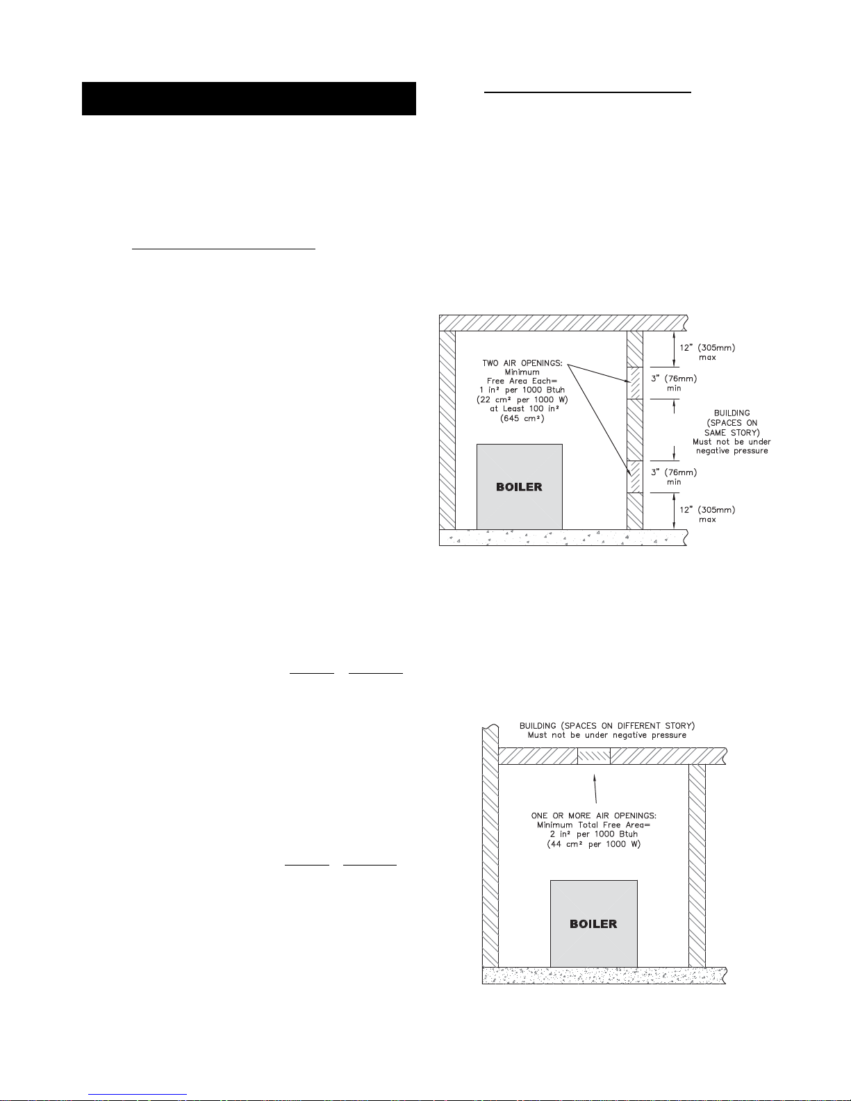
a. Combining spaces on the same floor:
Provide two permanent openings communicating
with additional spaces that have a minimum free
area of 1 in
2
per 1000 Btu/hr (22 cm2per 1000 W)
of the total input rating of all gas fired equipment
but not less than 100 in
2
(645 cm2). One
opening is to begin within 12 inches (305 mm)
from the top of the space and the other is to
begin within 12 inches (305 mm) from the floor.
The minimum dimension of either of these
openings shall be 3 inches (76 mm). See Figure
1.1 for an illustration of this arrangement.
b. Combining spaces on different floors:
Provide one or more permanent openings
communicating with additional spaces that have
a total minimum free area of 2 in
2
per 1000
Btu/hr (44 cm
2
per 1000 W) of total input rating
of all equipment. See Figure 1.2 for an
illustration of this arrangement.
4
Figure 1.1: Air Openings – All Air from Indoors
on the Same Floor
Figure 1.2: Air Openings – All Air from Indoors
on Different Floors
INSTALLATION AND OPERATING INSTRUCTIONS
21 ft
3
I
other
ACH 1000
Btu
/
hr
Required Volume
other
=
[]
15 ft
3
I
fan
ACH 1000
Btu
/
hr
Required Volume
fan
=
[]
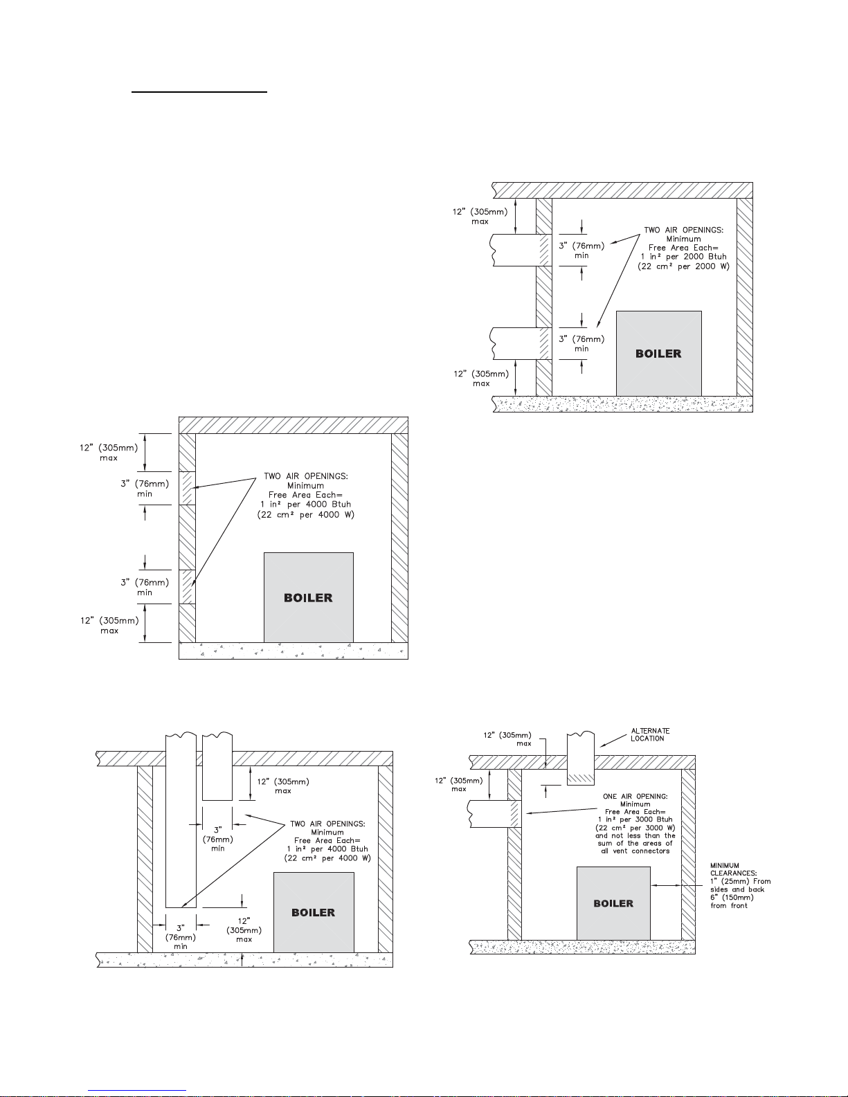
4. Outdoor Combustion Air: Outdoor combustion air is
to be provided through one or two permanent
openings. The minimum dimension of these air
openings is 3 inches (76 mm).
a. Two Per manent Opening Method: Provide
two permanent openings. One opening is to
begin within 12 inches (305 mm) of the top of
the space and the other is to begin within 12
inches (305 mm) of the floor. The openings are
to communicate directly or by ducts with the
outdoors or with spaces that freely communicate
with the outdoors. The size of the openings shall
be determined as follows:
i. Where communicating directly or through
vertical ducts with the outdoors each opening
shall have a minimum free area of 1 in
2
per
4000 Btu/hr (22 cm
2
per 4000 W) of total
input rating for all equipment in the space.
See Figure 1.3 for openings directly
communicating with the outdoors or Figure
1.4 for openings connected by ducts to the
outdoors.
ii. Where communicating with the outdoors
through horizontal ducts, each opening shall
have a minimum free area of 1 in
2
per 2000
Btu/hr (22 cm
2
per 2000 W) of total rated
input for all appliances in the space. See
Figure 1.5.
b. One Permanent Opening Method: Provide
one permanent opening beginning within 12
inches (305 mm) of the top of the space. The
opening shall communicate directly with the
outdoors, communicate through a vertical or
horizontal duct, or communicate with a space
that freely communicates with the outdoors. The
opening shall have a minimum free area of 1 in
2
per 3000 Btu/hr of total rated input for all
appliances in the space and not less than the
sum of the cross-sectional areas of all vent
connectors in the space. The gas-fired equipment
shall have clearances of at least 1 inch (25 mm)
from the sides and back and 6 inches (150 mm)
from the front of the appliance. See Figure 1.6
for this arrangement.
5
INSTALLATION AND OPERATING INSTRUCTIONS
Figure 1.3: Air Openings – All Air Directly from
Outdoors
Figure 1.4: Air Openings – All Air from Outdoors
through Vertical Ducts
Figure 1.5: Air Openings – All Air from Outdoors
through Horizontal Ducts
Figure 1.6: Air Openings – All Air from Outdoors
through One Opening

5. Combination Indoor and Outdoor Combustion Air: If
the required volume of indoor air exceeds the
available indoor air volume, outdoor air openings or
ducts may be used to supplement the available
indoor air provided:
a. The size and location of the indoor openings
comply with Subsection 3.
b. The outdoor openings are to be located in
accordance with Subsection 4.
c. The size of the outdoor openings are to be sized
as follows:
where:
A
req
= minimum area of outdoor openings.
A
full
= full size of outdoor openings calculated
in accordance with Subsection 4.
V
avail
= available indoor air volume
V
req
= required indoor air volume
6. Engineered Installations:
Engineered combustion air
installations shall provide an adequate supply of
combustion, ventilation, and dilution air and shall be
approved by the authority having jurisdiction.
7. Mechanical Combustion Air Supply:
a. In installations where all combustion air is
provided by a mechanical air supply system, the
combustion air shall be supplied from the
outdoors at the minimum rate of 0.35 ft
3
/min per
1000 Btu/hr (0.034 m
3
/min per 1000 W) of the
total rated input of all appliances in the space.
b. In installations where exhaust fans are installed,
additional air shall be provided to replace the
exhaust air.
c. Each of the appliances served shall be
interlocked to the mechanical air supply to
prevent main burner operation when the
mechanical air supply system is not in operation.
d. In buildings where the combustion air is provided
by the mechanical ventilation system, the system
shall provide the specified combustion air rate in
addition to the required ventilation air.
8. Louvers & Grills:
a. The required size of openings for combustion,
ventilation, and dilution air shall be based on the
net free area of each opening.
i. Where the free area through a louver or grille
is known, it shall be used in calculating the
opening size required to provide the free area
specified.
ii. Where the free area through a louver or grille
is not known, it shall be assumed that wooden
louvers will have 25% free area and metal
louvers and grilles will have 75% free area.
iii. Nonmotorized dampers shall be fixed in the
open position.
b. Motorized dampers shall be interlocked with the
equipment so that they are proven in the full
open position prior to ignition and during
operation of the main burner.
i. The interlock shall prevent the main burner
from igniting if the damper fails to open
during burner startup.
ii. The interlock shall shut down the burner if
the damper closes during burner operation.
9. Combustion Air Ducts
a. Ducts shall be constructed of galvanized steel or
an equivalent corrosion- resistant material.
b. Ducts shall terminate in an unobstructed space,
allowing free movement of combustion air to the
appliances.
c. Ducts shall serve a single space.
d. Ducts shall not serve both upper and lower
combustion air openings where both such
openings are used. The separation between ducts
serving upper and lower combustion air
openings shall be maintained to the source of
combustion air.
e. Ducts shall not be screened where terminating in
an attic space.
f. Horizontal upper combustion air ducts shall not
slope downward toward the source of the
combustion air.
g. The remaining space surrounding a chimney
liner, gas vent, special gas vent, or plastic piping
installed within a masonry, metal, or factory built
chimney shall not be used to supply combustion
air.
h. Combustion air intake openings located on the
exterior of buildings shall have the lowest side of
the combustion air intake opening at least 12
inches (305 mm) above grade.
6
INSTALLATION AND OPERATING INSTRUCTIONS
Liquefied Petroleum (LP) is heavier than air and may
collect or “pool” in a low area in the event of a leak
from defective equipment. This gas may then ignite,
resulting in a fire or explosion.
WARNING
V
avail
1 –
V
req
A
req
= A
full
x
[]
A. CHIMNEY OR VENT
1. Inspect the existing chimney or vent system. Make
sure it is in good condition. Inspect chimney liner
and repair or replace if necessary.
2. The vent system and installation must be in
accordance with Venting of Equipment chapter of
the current edition of the National Fuel Gas Code,
ANSI Z223.1/NFPA 54, or applicable provisions of
the local building codes.
3. Chimney/Vent Operation: The vent system must be
sized and installed to provide the draft needed to
remove all combustion products. If the vent system
does not provide enough draft, combustion products
will spill into the building from the draft hood relief
opening. If spillage of combustion products occurs,
check the vent system, the combustion and
ventilation openings and make sure the boiler room
is never under negative pressure.
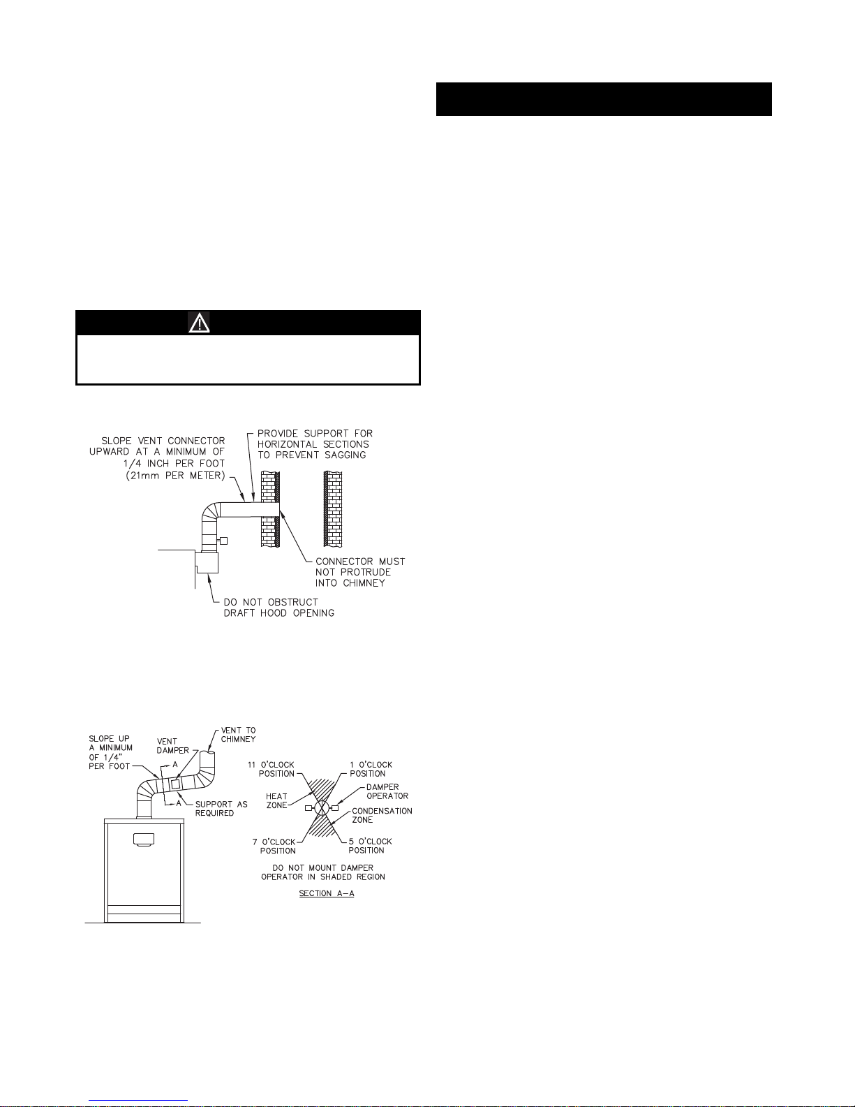
4. Vent Connection to Boiler:
a. Support the weight of the vent system
independently of the boiler draft hood. The draft
hood is not designed to carry structural loading.
b. Provide support of the vent connector
(breeching) at maximum 12 foot intervals to
prevent sagging and to provide a minimum
upward slope of 1/4" per foot.
c. Do not connect the vent for this boiler into any
vent system which operates with positive
pressure.
d. The vent connector must be single wall steel or
Type B double wall vent pipe. The vent
connector must be Type B double wall if it is
located in or passes through cold areas. The vent
connector must extend into, but not beyond, the
inside wall of the chimney.
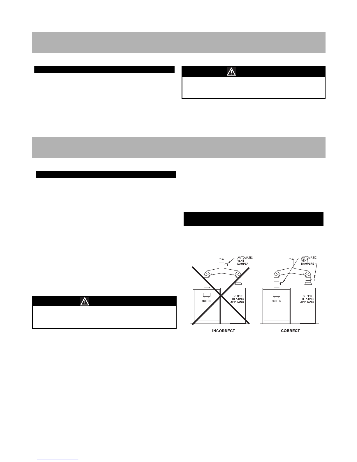
B. AUTOMATIC VENT DAMPER
INSTALLATION – GENERAL
1. Do not use one vent damper to control two or more
heating appliances. See Figure 3.1.
2. Follow these and the installation instructions
included with the vent damper. Observe the cautions
and warnings that accompany all instructions.
3. Provide minimum 6 inch (152 mm) clearance
between automatic vent damper and combustible
construction. Increase clearance if required by vent
damper manufacturer’s instructions. Provide
adequate space for vent damper access and service.
Failure to provide adequate venting can result in
severe personal injury or death.
WARNING
3. VENTING
A. PACKAGED BOILER
1. Remove the crate top and sides and remove any
loose cartons.
2. Lift the boiler from the crate pallet. Move the boiler to
the location determined in Chapter 1: Pre-installation.
3. Proceed to Chapter 3: Venting.
7
INSTALLATION AND OPERATING INSTRUCTIONS
2. BOILER PLACEMENT & ASSEMBLY
Be careful not to damage the burner tray when
removing the boiler from the pallet. If necessary,
remove the burner tray before moving the boiler.
NOTICE
Figure 3.1: Venting Multiple Appliances
8
INSTALLATION AND OPERATING INSTRUCTIONS
4. The automatic vent damper can be mounted directly
onto the draft hood outlet or in vent piping close to
the boiler.
See Figure 3.2 for installation with vent damper
mounted in vertical position. See Figure 3.3 for
installation with vent damper mounted in horizontal
position. Mount the unit to avoid excessive heat on
the operator or condensation drips into the operator.
a. Orient the vent damper operator to facilitate
connection of the vent damper harness to
knockout on right side of boiler.
b. Orient vent damper direction arrow in direction
of vent gas flow. Direction arrow must be visible
from front of boiler.
C. BOILER REMOVAL FROM COMMON
VENTING SYSTEM
When an existing boiler is removed from a common
venting system, the common venting system is likely to
be too large for proper venting of the remaining
appliances connected to it.
At the time of removal of an existing boiler, follow these
steps with each appliance remaining connected to the
common venting system placed in operation, while the
other appliances remaining connected to the common
venting system are not in operation:
a. Seal any unused openings in the common venting
system.
b. Visually inspect the venting system for proper size
and horizontal pitch and determine there is no
blockage or restriction, leakage, corrosion and other
deficiencies which could cause an unsafe condition.
c. Insofar as is practical, close all building doors and
windows and all doors between the space in which
the appliances remaining connected to the common
venting system are located and other spaces of the
building. Tur n on any clothes dr yers and any
appliance not connected to common venting system.
Tur n on any exhaust fans, such as range hoods and
bathroom exhausts, so they will operate at maximum
speed. Do not operate a summer exhaust fan. Close
fireplace dampers.
d. Place in operation the appliance being inspected.
Follow the lighting instructions. Adjust thermostat so
appliance will operate continuously.
e. Test for spillage at the draft hood relief opening after
5 minutes of main burner operation. Use the flame
of a match or candle, or smoke from a cigarette,
cigar, or pipe.
f. After it has been determined that each appliance
remaining connected to the common venting system
properly vents when tested as outlined above, return
doors, windows, exhaust fans, fireplace dampers and
any other gas-burning appliance to their previous
conditions of use.
g. Any improper operation of the common venting
system should be corrected so that the installation
conforms with the National Fuel Gas Code, ANSI
Z223.1/NFPA 54 or CAN/CGA B149 Installation
Codes. When resizing any portion of the common
venting system, the common venting system should
be resized to approach minimum size as determined
using the appropriate tables located in the chapter
“Sizing of Category I Venting Systems,” of the
National Fuel Gas Code, ANSI Z223.1/NFPA 54 or
CAN/CGA B149 Installation codes.
Figure 3.2: Venting with Vent Damper
in Vertical Position
Damper must be in open position when appliance
main burner is operating.
CAUTION
Figure 3.3: Venting with Vent Damper
in Horizontal Position
9
INSTALLATION AND OPERATING INSTRUCTIONS
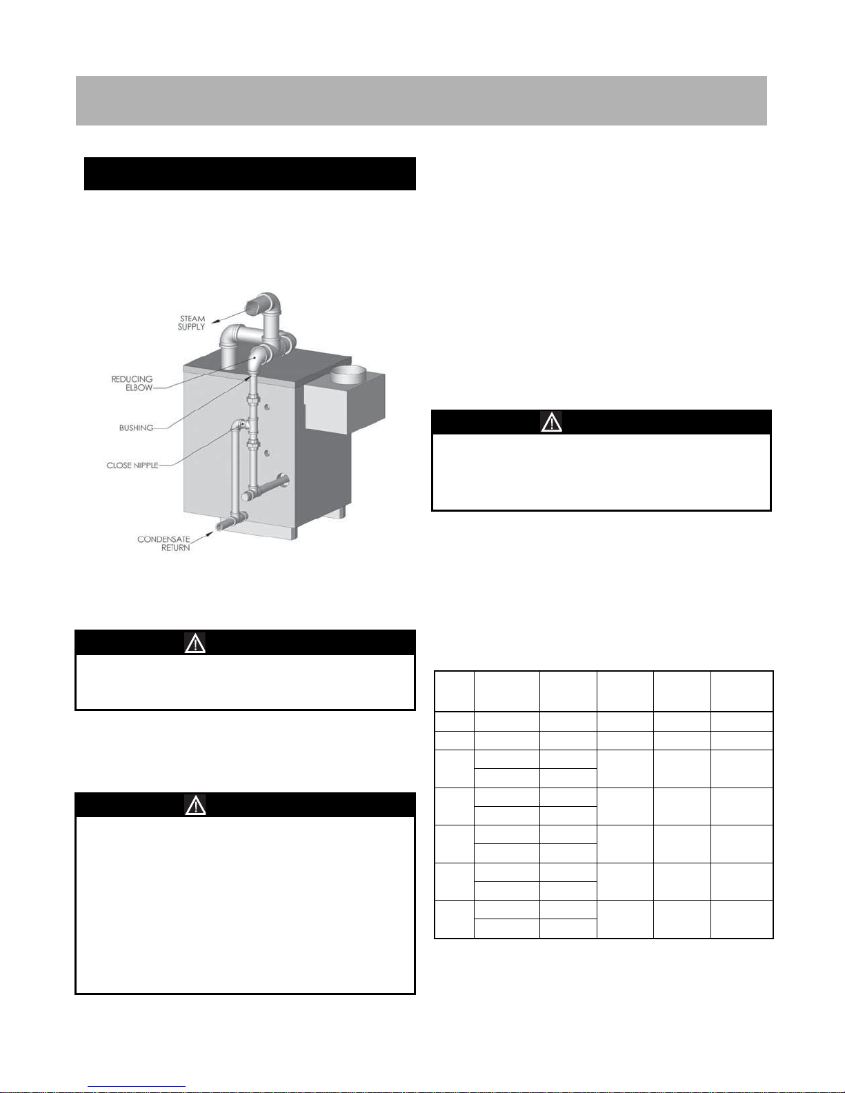
A. STEAM BOILER PIPING – SINGLE
BOILERS
1. Install steam supply pipes as shown in Figure 4.1. The
minimum quantity and size of supply pipes are
indicated in Table 4.1.
2. Pipe the steam header a minimum of 24" above the
normal water line using swing joints to attach the
risers into the steam header.
3. Use threaded fittings for manifold piping to provide
flexibility for thermal expansion.
4. Connect the equalizing line as shown in Figure 4.1
assuring that the reducing elbow is facing down and
that any bushings are vertical to prevent water buildup in the steam header.
5. The use of a Hartford Loop in all installations is
recommended to ensure reliability of the system. A
check is required on the pump discharge of all
pumped return systems.
6. On pumped return systems, install a globe valve after
the pump to allow throttling of the pump discharge.
The pressure downstream of the boiler cock should
be no more than 5 psig above the boiler operating
pressure.
7. Pipe the Hartford Loop such that the top of the close
nipple is 2 to 4 inches below the boiler normal water
line.
8. If the boiler feed pump discharge piping is elevated
at any point above the boiler water line, install
spring-loaded check valves at both the pump
discharge and at the connection to the boiler.
4. BOILER PIPING
Figure 4.1: Steam Piping – Single Supply
Connection
Use swing joints to attach to the header to avoid
damage to the boiler due to thermal expansion and
contraction of steam header pipe.
NOTICE
Use Threaded Fittings for Manifold Piping
• Do not use bushings or concentric reducers in the
horizontal header piping. This will prevent water
from dropping into the equalizer and cause water
carryover into the steam piping.
• Do not reduce the size or number of steam supply
risers below the minimum shown in Table 4.1.
Insufficient or undersized risers can cause damage
to the boiler.
• Do not use a bullhead tee to provide steam supply
to the system. This will cause water carryover into
the steam piping.
NOTICE
Always locate the steam supply take-off of the main
header between the equalizer and the last boiler
supply riser. Locating the steam supply between the
risers will cause a bullhead tee and cause water
carryover into the system.
NOTICE
Table 4.1: Steam Supply and Header Pipe Sizing
Boiler
Model
Number of
Supply
Connections
Supply
Size (NPS)
Header
Size (NPS)
Equalizer
Size (NPS)
Evaporation
Rate (GPM)
88 1 2 2 1-1/4 0.11
118 1 2 2 1-1/4 0.15
147
1 2-1/2
2-1/2 1-1/4 0.19
2* 2*
177
1 2-1/2
2-1/2 1-1/4 0.23
2* 2*
206
1 3
3 1-1/4 0.27
2* 2*
236
1 3
3 1-1/4 0.31
2* 2*
288
1 3
3 1-1/4 0.37
2* 2-1/2*
*Dual supplies may be used in lieu of larger single supply.
INSTALLATION AND OPERATING INSTRUCTIONS
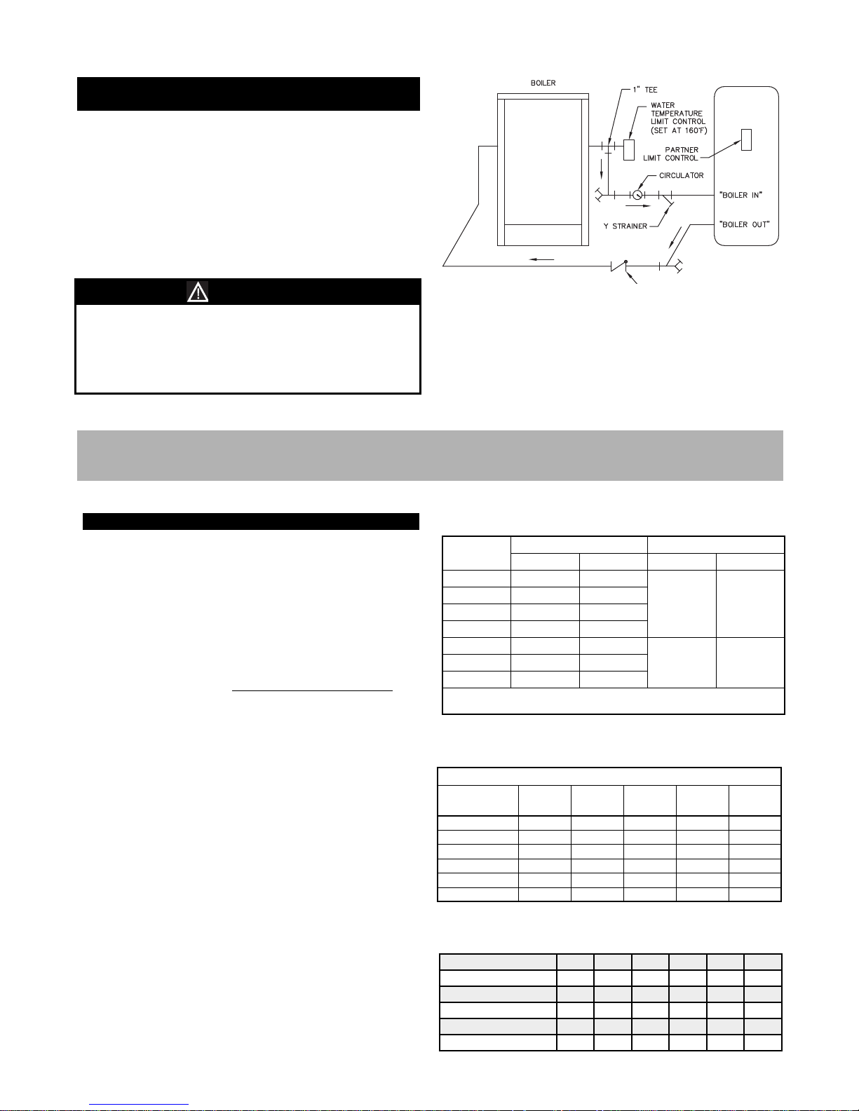
B. STEAM BOILER INDIRECT WATER
HEATER PIPING
1. See Figure 4.2 for typical installation.
2. Install Boiler Water Temperature Limit Control in 1"
Tee on supply connection (same side of boiler as low
water cut-off). Set Limit at 160°F to avoid steam
generation during periods when only the domestic
water is calling for heat.
3. Install circulator and strainer in supply piping. Install
check valve to prevent gravity circulation.
Maintain water level near normal water line to avoid
steam generation during periods when only the
domestic water is calling for heat.
Tank performance reduced when supplied by steam
boiler.
NOTICE
Figure 4.2: Typical Steam Boiler Indirect
Water Heater Piping
A. INSTALLATION
1. Pipe gas to the boiler in accordance with local codes.
In the absence of local regulations refer to the
National Fuel Gas Code, ANSI Z223.1/NFPA 54.
2. Size and install the gas supply piping to provide a
supply of gas sufficient to meet the maximum demand
of all appliances without excessive pressure drop.
3. The rate of gas to be provided to the boiler can be
determined by:
Obtain the gas heating value of the gas from the gas
supplier. As an alternative use Table 5.1.
4. Table 5.2 shows the maximum flow capacity of
several pipe sizes based on 0.3 inches of water
pressure drop. These values are based on a specific
gravity of 0.60. Apply the factors indicated in Table
5.3 for gas with specific gravity other than 0.60 to
obtain corrected capacities.
5. FUEL PIPING
Based on Specific Gravity of 0.60
Pipe Length
(Feet)
1/2"
Pipe
3/4"
Pipe
1"
Pipe
1-1/4"
Pipe
1-1/2"
Pipe
10 132 278 520 1,050 1,600
20 92 190 350 730 1,100
30 73 152 285 590 890
40 63 130 245 500 760
50 56 115 215 440 670
60 50 105 195 400 610
Table 5.2: Maximum Capacity of Pipe in CFH for a
Pressure Drop of 0.3" of Water
Table 5.3: Maximum Capacity Correction Factors
Specific Gravity other than 0.60
Table 5.1: Gas Input & Valve Inlet
Specific Gravity 0.50 0.55 0.60 0.65 0.70 0.75
Correction Factor 1.10 1.04 1.00 0.96 0.93 0.90
Specific Gravity 0.80 0.85 0.90 1.00 1.10 1.20
Correction Factor 0.87 0.84 0.82 0.78 0.74 0.71
Specific Gravity 1.30 1.40 1.50 1.60 1.70 1.80
Correction Factor 0.68 0.66 0.63 0.61 0.59 0.58
Boiler Input (BTU/HR)
CFH =
Gas Heating Value (BTU/FT³)
Model
Gas Input1(CFH) Gas Valve Inlet2(NPT)
Nat. Gas LP Gas Nat. Gat LP Gas
88 88.5 35.4
1/2" 1/2"
118 118.0 47.2
147 147.5 59.0
177 177.0 70.8
206 206.5 82.6
3/4" 3/4"
236 236.0 94.4
288 287.5 115.0
1. Natural Gas Based on 1000 Btu./Cubic Foot, LP Gas Based on 2500 Btu./Cubic Foot.
2. See instructions for sizing gas supply piping.
10
 Loading...