

HydroTherm R-180C, R-210C, R-250C, R-300B Installation, Operation & Maintenance Manual & Replacement Parts List
MMOODDEELL RR SSEERRIIEESS
IINNSSTTAALLLLAATTIIOONN,,
OOPPEERRAATTIIOONN &&
MMAAIINNTTEENNAANNCCEE
MMAANNUUAALL &&
RREEPPLLAACCEEMMEENNTT
PPAARRTTSS LLIISSTT
RRCC22--1100004
4
4422--99115599
GGaass--FFiirreedd WWaatteerr CCaasstt IIrroonn BBooiilleerrss
118800,,000000 ttoo 330000,,000000 BBttuuhh IInnppuut
SSttaannddiinngg PPiilloott,, IInntteerrmmiitttteenntt PPiilloott &
VVeenntt DDaammppeer
SSEECCTTIIOONN 11:: BBOOIILLEERR IINNSSTTAALLLLAATTIIOON
Introduction............................................................ 2
Step 1: Locating & Setting Boiler........................... 3
Step 2: Installing/Purging Water Piping................. 5
Step 3: Venting Boiler............................................ 8
Step 4: Installing/Testing Gas Piping..................... 10
Step 5: W
SSEECCTTIIOONN 22:: SSTTAARRTT--UUPP&& OOPPEERRAATTIIOON
Safety Controls......................................................
Start-Up & Adjustments.........................................
iring Boiler.............................................. 11
r
N
N
t
&
17
17
SSEECCTTIIOONN 33:: MMAAIINNTTEENNAANNCCE
Water Treatment.................................................... 20
Freeze Protection................................................... 20
Before Each Heating Season................................
o Change Orifices........................................
How T
Troubleshooting..................................................... 21
(French V
Appendix
Replacement Parts List.......................................... 23
A
E
20
21
ent Damper Translation)..... 22
TES: 260 NOR
A
UNITED
IN
IN CANADA: 5211 CREEKBANK ROAD, MISSISSAUGA, ONT. L4W IR3 (905) 625-2991/FAX (905) 625-6610
ST
TH ELM ST., WESTFIELD, MA 01085 (413) 564-5515/FAX (413) 568-9613
AANNSSII//AASSMMEE CCOODDEE CCOOMMPPLLIIAANNCCEE:
D
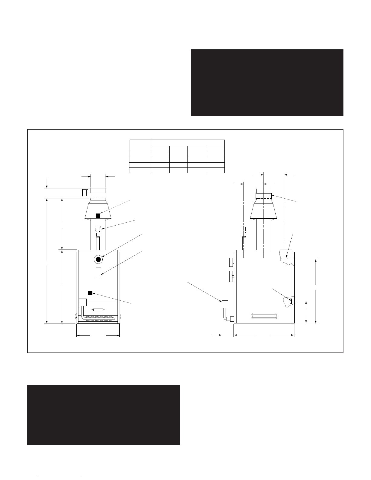
*LOCATED IN FRONT ON MODELS R-180C
AND R-210C
PRESS. RELIEF VALVE
TEMP./PRESS. INDICATOR
HI-LIMIT AQUASTAT
7"
GAS VALVE
*
2" SUPPLY
BOILER
MODEL
R-300B
R-250C
R-210C
R-180C 28-1/4" 58-5/8" 7"21-7/8"
DIMENSIONS
ABCD
28-1/4"
32-1/4"
28-7/8"
61-7/8"
65-5/8"7"7"
8"
32-1/4"
29-3/8" 66-1/8"
25-1/8"
B
2" RETURN
9-1/2"
9-1/2"
12"
SPILL SWITCH
ROLLOUT
SWITCH
NOTE: SPILL & ROLLOUT
SWITCHES USED ON
R-180 THRU R-250.
VENT DAMPER
3 5/8"
C
36 3/4"
21 1/4"
A
25 1/2"
:
Installation must
conform to requirements of authority having jurisdiction
or, in absence of such requirements, to National Fuel
as Code ANSI Z223.1-latest edition and to National
G
Electric Code NFPA-70-latest edition. Where required by
authority having jurisdiction, installation must also conform to Standard for Controls and Safety Devices for
utomatically Fired Boilers, ANSI/ASME CSD-1.
A
BBOOIILLEERR SSHHIIPPMMEENNTT::
Each boiler is shipped in a single
carton. There is a vent damper packed separately with
the boiler (for model R-300 vent damper is optional)
WWAARRNNIINNGG:: IInnssttaalllleerrss mmuusstt ffoollllooww llooccaall rreegguullaattiioonns
wwiitthh rreessppeecctt ttoo tthhee iinnssttaallllaattiioonn ooff CCOO ddeetteeccttoorrss aannd
ffoollllooww tthhee mmaannuuffaaccttuurreerr''ss ssttaatteedd mmaaiinntteennaanncce
sscchheedduullee ffoorr tthhiiss bbooiilleerr!
!
s
d
e
For Canada, the installation must be in accordance with
Standards CAN/CGA-B149 (.1 or .2) Installation Codes
for Gas Burning Appliances and Equipment and with
Standard C.S.A. C22.1 Canadian Electrical Code, Part 1
and Part 2, and/or local codes.
AATTTTEENNTTIIOONN:: OObbsseerrvveerr lleess rrèègglleemmeennttss rrèèggiioonnaall àà ll''eeggaarrdd ddeess ddéétteecctteeuurrss ddee mmoonnooxxyyddee ddee ccaarrbboonnee eet
oobbsseerrvveerr eennttrreettiieenn ddee mmaannuuffaaccttuurriieerr ppoouurr cceetttte
cchhaauuddiièèrree!
!
t
e
The following terms are used throughout this manual to bring attention to the presence of potential hazards or to
important information concerning the product:
DDAANNGGEERR:: IInnddiiccaatteess aann iimmmmiinneennttllyy hhaazzaarrddoouuss ssiittuuaattiioonn wwhhiicchh,, iiff nnoott aavvooiiddeedd,, wwiillll rreessuulltt iinn ddeeaatthh,, sseerriioouuss iinnjjuurryy oorr ssuubbssttaannttiiaall pprrooppeerrttyy ddaammaaggee.
WWAARRNNIINNGG:: IInnddiiccaatteess aa iimmmmiinneennttllyy hhaazzaarrddoouuss ssiittuuaattiioonn wwhhiicchh,, iiff nnoott aavvooiiddeedd,, ccoouulldd rreessuulltt iinn ddeeaatthh,, sseerriioouuss iinnjjuurryy oorr ssuubbssttaannttiiaall pprrooppeerrttyy ddaammaaggee.
MMOODDEELL RR BBOOIILLEERR DDIIMMEENNSSIIOONNSS
.
.
CCAAUUTTIIOONN:: IInnddiiccaatteess aa iimmmmiinneennttllyy hhaazzaarrddoouuss ssiittuuaa-
-
ttiioonn wwhhiicchh,, iiff nnoott aavvooiiddeedd,, mmaayy rreessuulltt iinn mmiinnoorr iinnjjuurry
-
oorr pprrooppeerrttyy ddaammaaggee.
NNOOTTEE:: UUsseedd ttoo nnoottiiffyy ooff ssppeecciiaall iinnssttrruuccttiioonnss oon
-
iinnssttaallllaattiioonn,, ooppeerraattiioonn oorr mmaaiinntteennaannccee wwhhiicchh aarre
-
iimmppoorrttaanntt ttoo eeqquuiippmmeenntt bbuutt nnoott rreellaatteedd ttoo ppeerrssoonnaal
iinnjjuurryy hhaazzaarrddss.
.
.
-
y
n
e
l
2
SSEECCTTIIOONN 11:: BBOOIILLEERR IINNSSTTAALLLLAATTIIOON
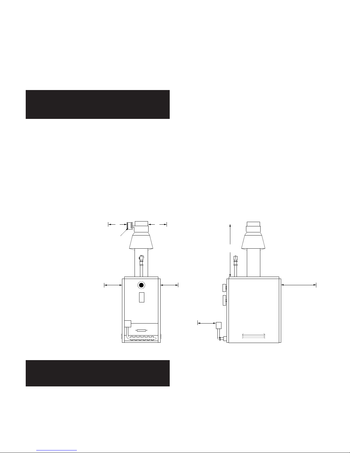
FRONT
ALCOVE
REAR
(6")
W/O CIRC.
24" WITH
CIRCULATOR
(RECOMMENDED
FOR SERVICING)
RECOMMEND
MORE FOR
ACCESS TO
VENT DAMPER
POSITION
INDICATOR
VENT
DAMPER
6" 6"
LEFT
6"
SIDE
VIEW
FRONT
VIEW
TOP
38"
RIGHT
6"
N
SSTTEEPP11:: LLOOCCAATTIINNGG && SSEETTTTIINNGG TTHHEE BBOOIILLEER
R
PPRROOCCEEDDUURREE AA:: CChheecckk tthhaatt pprroovviissiioonnss ffoorr ccoommbbuussttiioonn aaiirr aarree iinn aaccccoorrddaannccee wwiitthh NNaattiioonnaall FFuueell GGaass CCoodde
AANNSSII ZZ222233..11--llaatteesstt eeddiittiioonn aanndd aallll aapppplliiccaabbllee llooccaall ccooddeess.. IInn CCaannaaddaa,, ffoollllooww CCAANN//CCGGA
BB114499((..11 oorr ..22)) iinnssttaallllaattiioonn ccooddeess.
.
WWAARRNNIINNGG:: AAddeeqquuaattee ffrreesshh aaiirr mmuusstt bbee pprroovviiddeedd ffoor
ccoommbbuussttiioonn.. OOtthheerrwwiissee,, iimmpprrooppeerr bbooiilleerr ooppeerraattiioon
aanndd iinnaaddeeqquuaattee vveennttiinngg ooff ddeeaaddllyy fflluuee ggaasseess mmaay
.
rreessuulltt.
When communicating directly with the outside, each
r
opening must have a minimum free area of one square
n
inch per 4000 Btu/hr of gas input. When ventilation air is
y
provided by openings in doors, etc. to adjoining spaces
A
having adequate infiltration, each opening must have a
IIff bbooiilleerr iiss iinnssttaalllleedd iinn aann uunnccoonnffiinneedd ssppaaccee,
,
adequate
air will be available via normal infiltration.
IIff bbooiilleerr iiss iinnssttaalllleedd iinn aa ccoonnffiinneedd ssppaacce
e
(a space with
a volume of less than 50 cubic feet per 1000 Btu/hr of
gas input for all fuel burning equipment) or building construction is unusually tight, adequate air for combustion
must be provided by two openings: one located about 6”
minimum free area of one square inch per 1000 Btu/hr of
gas input.
NNOOTTEE:: BBooiilleerr eemmppllooyyss aattmmoosspphheerriicc ccoommbbuussttiioonn.
CCoommbbuussttiioonn aaiirr mmuusstt nnoott bbee ccoonnttaammiinnaatteedd wwiitthh hhaallooggeennaatteedd hhyyddrrooccaarrbboonn vvaappoorrss,, aaeerroossooll pprrooppeellllaannttss oor
ffrreeoonn;; ootthheerrwwiissee,, hheeaatt eexxcchhaannggeerr wwiillll bbeessuubbjjeecctt tto
ccoorrrroossiioonn,, rreedduucciinngg bbooiilleerrlliiffee.
.
below the ceiling, the other about 6” above the floor.
e
.
-
r
o
PPRROOCCEEDDUURREE BB:: CChheecck
mmiinniimmuumm cclleeaarraanncceess tto
ccoommbbuussttiibblleess aarree pprrooppeer
aass sshhoowwnn.. LLooccaall rreeqquuiirreemmeennttss mmaayy ssppeecciiffy
ggrreeaatteerr cclleeaarraanncceess && mmuusst
bbee aadd--hheerreedd ttoo.
BBooiilleerr sshhaallll bbee iinnssttaallll--eed
ssuucchh tthhaatt tthhee ggaass iiggnniittiioon
ssyysstteemm ccoommppoonneennttss aarre
pprrootteecctteedd ffrroomm wwaatteer
((ddrriippppiinngg,, sspprraayyiinngg,, rraaiinn,
eettcc..)) dduurriinngg aapppplliiaanncce
ooppeerraattiioonn aanndd sseerrvviiccee ((cciirrccuullaattoorr rreeppllaacceemmeenntt,, ccoonnddeennssaattee ttrraapp,, ccoonnttrrool
rreeppllaacceemmeenntt,, eettcc..)).
WWAARRNNIINNGG:: NNeevveerr iinnssttaallll bbooiilleerr oonn ccoommbbuussttiibbllee fflloooorriinngg oorr ccaarrppeettiinngg aass hheeaatt ddaammaaggee aanndd//oorr ffiirree mmaay
rreessuulltt.
.
.
.
k
o
r
-
y
t
d
n
e
r
,
e
-
l
NNOOTTEE:: DDoo nnoott lloooosseenn ttiiee rrooddss oonn aabbssoorrppttiioonn uunniitt.
-
TThheeyy aaccccoommmmooddaattee tthheerrmmaall eexxppaannssiioonn.. LLoossss ooff bbooiill-
y
eerr ssttrruuccttuurraall iinntteeggrriittyy aanndd wwaatteerr lleeaakkss//ddaammaaggee mmaay
.
rreessuulltt.
CCAAUUTTIIOONN:: LLooccaattee bbooiilleerr ssoo hhoorriizzoonnttaall ccoonnnneeccttiinng
fflluuee ppiippee iiss aass sshhoorrtt aass ppoossssiibbllee.. MMaaxxiimmiizzee hheeiigghhtt oof
vveerrttiiccaall fflluuee ccoonnnneeccttoorr.
.
FIGURE 1.1
.
-
y
g
f
3
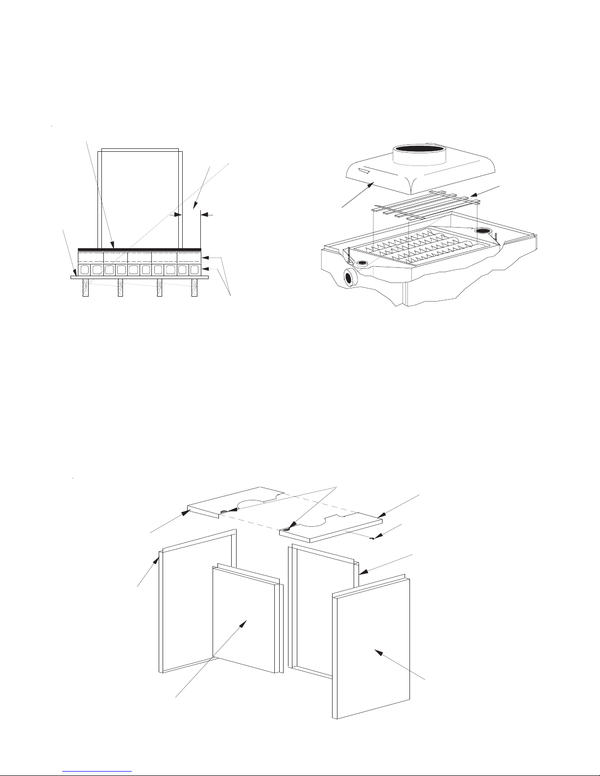
BAFFLE
GRID
DOME
6"
4
" HOLLOW CLAY TILE (TWO COURSES) OPENINGS THRU
B
LOCKS IN TOP COURSE TO BE AT 90 ANGLE TO OPENINGS
THRU BOTTOM COURSE
0
22 GAUGE
SHEETMETAL
FLOOR
6" OVERHANG
OF BLOCK AND
SHEETMETAL
A
LL AROUND
LEFT TOP PANEL
FRONT PANEL
(BOILER MOUNTED)
RIGHT SIDE PANEL
RIGHT TOP PANEL
LEFT SIDE PANEL
REAR PANEL
REMOVE KNOCK-OUT
ASSEMBLY SCREW
PPRROOCCEEDDUURREE CC:: CChheecckk ccoommppoonneenntt ppoossiittiioonniinngg..
1. Remove all packing material from boiler.
. Install boiler on non-combustible flooring only, unless
2
local codes permit use and fabrication of a recommended fireproof base (see Figure 1.2A).
FIGURE 1.2A FIGURE 1.2B
3. Check that burners and controls are in the proper
position.
. Check proper seating of baffle grid inside of dome
4
opening (see Figure 1.2B).
PPRROOCCEEDDUURREEDD:: IInnssttaallll jjaacckkeett.
.
1. Unpack jacket parts from carton and check that quantity is correct: two side panels, one rear panel, one left
top panel and one right top panel (see Figure 1.3).
2. Stand left and right side panels in place and fasten to
front panel with screws provided. Fasten side panels to
rear panel in same manner.
3. Lock left and right halves of top panel together and fasten to side panels with screws provided.
FIGURE 1.3
4
SHUT-OFF
VALVE
VERTICAL EXPANSION TANK
ARRANGEMENT (PREFERRED)
DRAIN VALVE
SHUT-OFF
VALVE
PRESS.
RELIEF
VALVE
AIR VENT
SHUT-OFF
VALVE
PRESSURE
REDUCING
(FILL) VALVE
SHUT-OFF
VALVES
CIRCULATOR
DRAIN VALVE
HORIZONTAL EXPANSION
TANK ARRANGEMENT
DRAIN VALVE
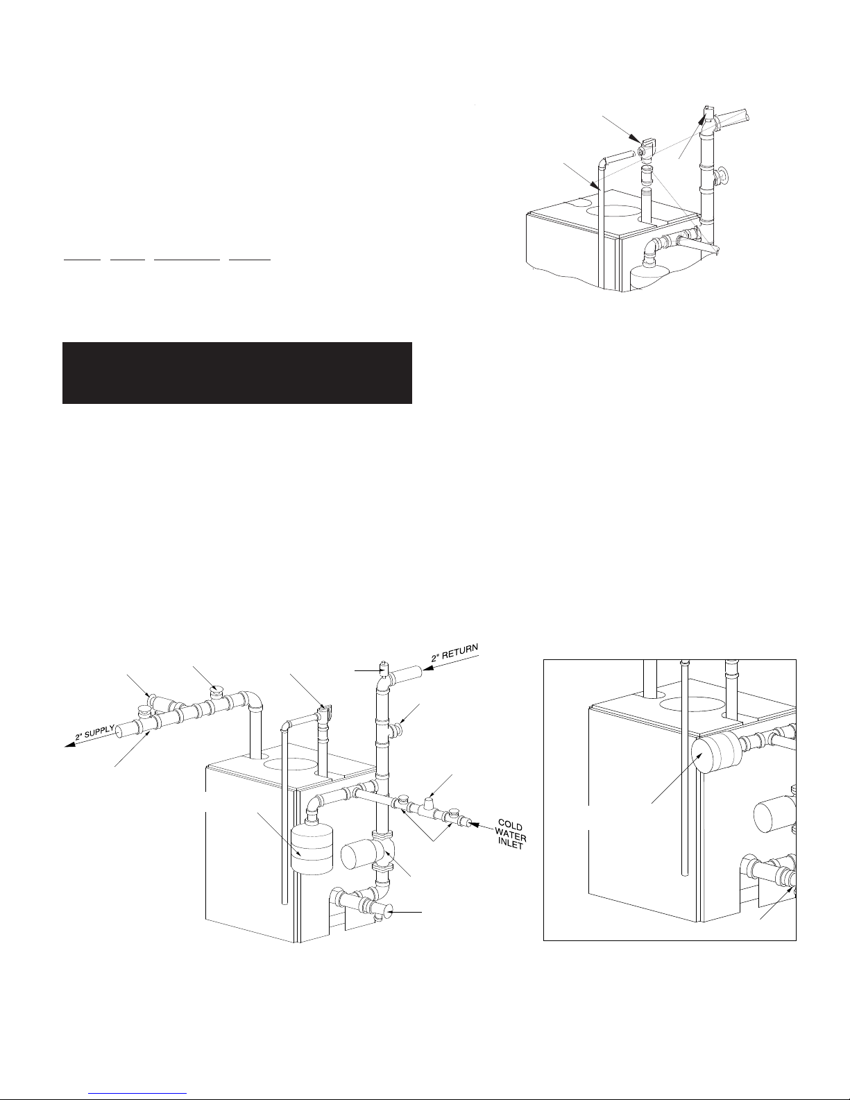
SSTTEEPP22:: IINNSSTTAALLLLIINNGG && PPUURRGGIINNGG WWAATTEERR PPIIPPIINNG
PRESS. RELIEF VALVE
AIR
VENT
RELIEF VALVE DISCHARGE
PIPING
G
NNOOTTEE:: BBooiilleerr mmuusstt nnoott bbee uusseedd wwiitthhoouutt ffoorrccee cciirrccuullaattiioonn,, aass oovveerrhheeaattiinngg oorr ffaaiilluurree ooff ccaasstt iirroonn
sseeccttiioonnss mmaayy rreessuulltt.
PPRROOCCEEDDUURREE AA:: IInnssttaallll pprreessssuurree rreelliieeff vvaallvvee aannd
rreelliieeff vvaallvvee ddiisscchhaarrggee ppiippiinngg.. FFoorr MMooddeell RR--330000B
ssuuppppllyy oouuttlleett iiss aatt rreeaarr aanndd rreelliieeff vvaallvvee ppiippiinngg iiss aat
ffrroonntt ooff bbooiilleerr.
.
d
B
t
.
RReelliieeffVVaallvveeDDiisscchhaarrggeePPiippiinngg:: MMuusstt tteerrmmiinnaattee 66”
aabboovvee fflloooorr && bbee ssaammee ssiizzee oorr llaarrggeerr tthhaann vvaallvvee oouuttlleett.
WWAARRNNIINNGG:: NNoo vvaallvvee ooff aannyy ttyyppee mmaayy bbee iinnssttaalllleed
bbeettwweeeenn bbooiilleerr && rreelliieeff vvaallvvee ttoo pprreevveenntt aacccciiddeennttaal
eexxpplloossiioonn ffrroomm oovveerr--pprreessssuurree..
PPRROOCCEEDDUURREE BB:: IInnssttaallll ssuuppppllyy aanndd rreettuurrnn wwaatteer
ppiippiinngg.. FFoorr MMooddeellss RR--118800CC && 221100CC ssuuppppllyy oouuttlleett iis
aatt ffrroonntt ooff bbooiilleerr aanndd rreelliieeff vvaallvvee ppiippiinngg iiss aatt rreeaarr oof
.
bbooiilleerr.
-
”
.
CCAAUUTTIIOONN:: PPiippiinngg mmuusstt bbee iinnssttaalllleedd ffrroomm rreelliieeff vvaallvve
d
ddiisscchhaarrggee ssoo tthheerree wwiillll bbee nnoo ddaannggeerr ooff ssccaallddiinngg ppeerr-
l
ssoonnnneell.
r
IIff bbooiilleerr iiss iinnssttaalllleedd aabboovvee lleevveell ooff rraaddiiaattiioonn,, aa lloow
s
wwaatteerr ccuutt--ooffff mmuusstt bbee uusseedd.
.
.
f
AALLLLEEXXTTEERRNNAALLPPIIPPIINNGG MMUUSSTT BBEE SSUUPPPPOORRTTEEDD BBY
HHAANNGGEERRSS,, NNOOTT BBYYBBOOIILLEERR AACCCCEESSSSOORRIIEESS.
FIGURE 1.4
e
-
w
Y
.
FIGURE 1.5
5
S
UPPLY
R
ETURN
50%
120° F
100%
140° F
1
00%
160° F
50%
160° F
50%
160° F
SYSTEM
BYPASS
SUPPLY
RETURN
50%
120° F
100%
140° F
100%
160° F
50%
160° F
50%
160° F
PUMP AWAY
BYPASS
SUPPLY
RETURN
100%
120° F
200%
140° F
200%
160° F
100%
160° F
100%
160° F
PUMPED
BYPASS
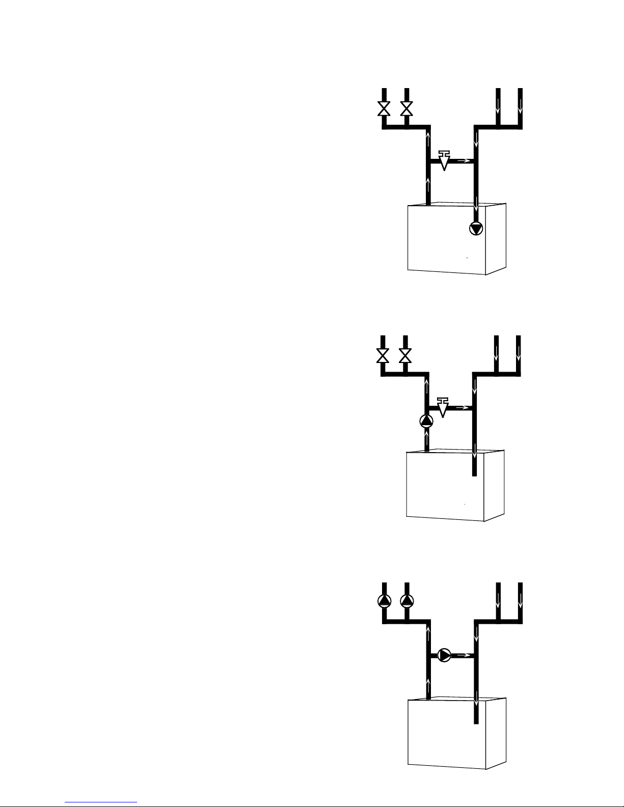
CCAAUUTTIIOONN:: TToo pprreevveenntt ddaammaaggee dduuee ttoo eexxcceessssiivvee ccoonnddeennssaattiioonn,, oonnee ooff tthhee ffoolllloowwiinngg ppiippiinngg ooppttiioonnss sshhoouulld
bbee uusseedd.
.
-
d
SSYYSSTTEEMM BBYYPPAASSS
S
For systems using a circulator on the return as either a
single zone, or multiple zones with zone valves, install a
system bypass line between the supply and return on the
suction side of the circulator (see Figure 1.6). Install a
etering valve in this bypass line to regulate the amount
m
of flow that will be diverted to the return. A plug valve
offers the best control for this application. Although other
valves may be less expensive, a plug valve will be easier
to set accurately.
In the absence of a flow indicator, set the metering valve
using temperature as a guide. The accompanying diagram suggests one scenario. This addition requires only
two tees, a plug valve, and a small amount of pipe and
offers the simplest approach to reliably control condensation. For this system and those that follow, be aware that
you are using a percentage of the pump capacity to
blend, but the friction loss for the entire pump flow has
been reduced. In most cases, the standard pump packaged with the boiler has enough capacity to feed the
baseboard distribution system and the bypass line.
PPUUMMPPAAWWAAYYBBYYPPAASSS
S
For systems that use a single circulator to pump away
from the boiler, the bypass should be installed on the discharge side of the circulator (see Figure 1.7). Full temperature water supplies the baseboard distribution system as before. Half of the circulator’s volume moves
through the bypass, blending and heating the cooler
return water. Again, the cost of installing the bypass is
small and setting it by temperature can be accomplished
with a contact thermometer.
FIGURE 1.6
PPUUMMPPEEDD BBLLEENND
D
An additional circulator can also be used to provide a
return water temperature blend. This method works well
with systems with multiple zones with circulators (see
Figure 1.8). The dedicated bypass circulator provides a
strong blending flow without diminishing the flow available to any heating zone. Any residentially sized circulator is adequate for this purpose.
Each of these bypass solutions also has the added benefit of increasing circulation in the boiler which will maxi
mize tankless coil output and increase the accuracy of
temperature sensing controls.
FIGURE 1.7
-
FIGURE 1.8
6
VALVE “C”
VALVE “B”
VALVE “A”
VALVE “D”
VALVE “E”
VALVE “F”
NOTE: VALVES "H" OPENED ON HEATING WITH "C" VALVES
CLOSED REVERSE PROCEDURE ON COOLING.
EXP. TANK
VENT
ROOM
UNIT
DRAIN
CHILLER
BOILER
HCP
UMP
RELIEF
VALVE
FILL
VALVE
DRAINCH
BOILER
reverse
aquastat
N.O.
T
T
t'stat
G
V
115 volts
24 volts
circulator
operating
aquastat
N.C.
REVERSE
AQUASTAT
SET AT 120° F
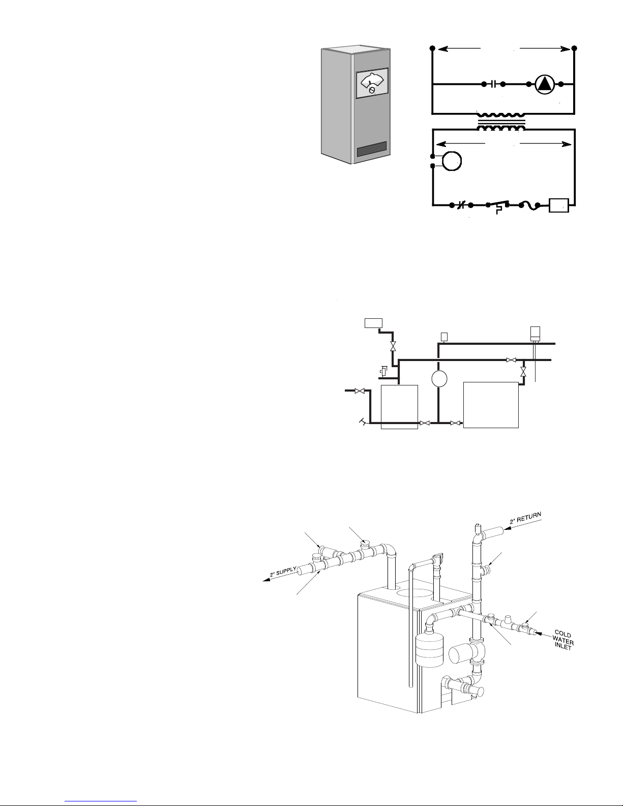
RREEVVEERRSSEE AACCTTIINNGG AAQQUUAASSTTAATTS
S
An alternative for existing systems experiencing condensation that does not require re-piping the boiler utilizes a
reverse acting aquastat, one that makes on temperature
ise. This approach works best in single zone systems.
r
Wired in series with the circulator, this control holds the circulator off until the boiler reaches an acceptable temperature and then starts system circulation (see Figure 1.9).
he most commonly available reverse acting aquastat is
T
a Honeywell L4006B. The aquastat should be mounted in
an immersion well directly installed in the boiler. The use
of heat conductive grease (Honeywell part # 972545) in
the immersion well is strongly recommended for fast and
accurate temperature response. Set this adjustable
aquastat to make at no less than 130° F. While this
method can cause the circulator to cycle more frequently,
setting the aquastat’s differential to the maximum (2530°F) will minimize short cycling.
FIGURE 1.9
PPRROOCCEEDDUURREE CC:: FFoorr ccoommbbiinnaattiioonn hheeaattiinngg aanndd ccoooolliinngg iinnssttaallllaattiioonnss oonnllyy.
.
If a hot water boiler is installed in connection with a water
chiller, the chilled water must be piped in parallel with the
boiler, using appropriate valves to prevent the chilled
medium from entering the boiler (see Figure 1.10). When
boilers are connected to heating coils located in air handling units where they may be exposed to refrigerated air
circulation, such boiler piping system shall be equipped
with flow-control valves or other means to prevent gravity circulation of the boiler water during the cooling cycle.
PPRROOCCEEDDUURREE DD:: CCoommpplleetteellyy ffiillll && ppuurrgge
hheeaattiinngg ssyysstteemm.. MMaakkee ssuurree tthhaatt aallll hheeaattiinngg ssyysstteemm mmaannuuaall aaiirr vveennttss aarree cclloosseedd.
e
.
1. Check flow direction arrows on hydronic
components are facing in proper direction.
Attach hose to drain valve “B” and close
2.
valve “A”. Open valves “C”, “D”, “E” and “F”
and drain valve “B”. Fill system with water
until water runs out of the hose in a steady
stream (no visible air bubbles).
3. Close valves “C” and “D”. Open valve “A”.
When water runs out of the hose in a steady
stream (no visible air bubbles), close drain
valve “B”.
-
FIGURE 1.10
4. Open valves “C” and “D”.
FFOORR WWAATTEERR TTRREEAATTMMEENNTT && FFRREEEEZZEE PPRROOTTEECCTTIIOONN RREEQQUUIIRREEMMEENNTTSS,,
SSEEEE ““SSEECCTTIIOONN 33:: MMAAIINNTTEENNAANNCCEE”” IINN TTHHIISS MMAANNUUAALL
FIGURE 1.11
7
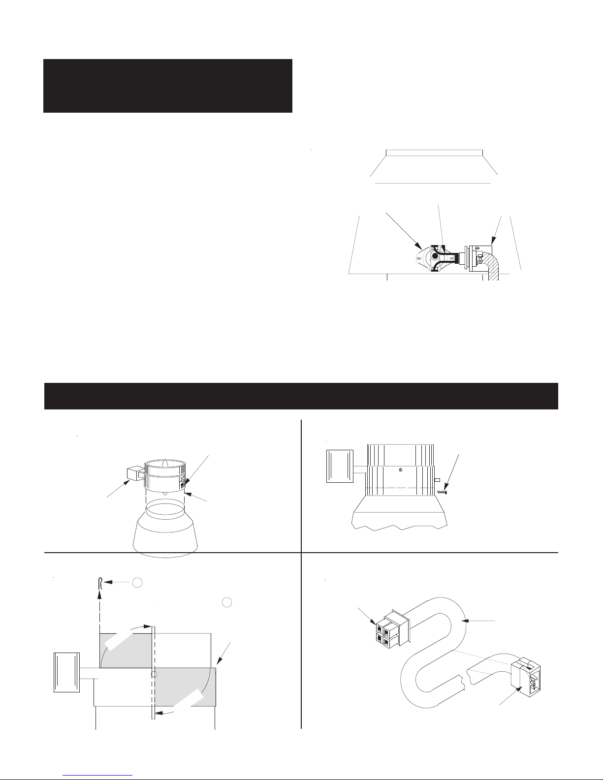
SSTTEEPP33:: VVEENNTTIINNGG TTHHEE BBOOIILLEER
FLOW DIRECTION
ARROW POINTS UP
MOUNT
VENT DAMPER
OVER
DRAFTHOOD
MAKE SURE
MOTOR IS
LOCATED
ON LEFT SIDE
ATTACH LOWER
PORTION OF
VENT DAMPER
TO DRAFTHOOD
WITH 1/2" OR
SHORTER SCREWS
OR POP RIVETS
OPEN
OPEN
1
REMOVE
SHIPPING
CLIP
2
OBSERVE
DAMPER
ROTATES
TO OPEN
POSITION
WITHOUT
OBSTRUCTION
PLUG INTO MOLEX
RECEPTACLE ON FRONT
OF BOILER
PLUG INTO MOLEX
RECEPTACLE INSIDE
DAMPER MOTOR
VENT
DAMPER
WIRE
HARNESS
I
NSTALL
SWITCH
IN OPENING
ON DRAFTHOOD
C
ONNECT
WIRE
LEADS
I
NSTALL
MOUNTING
BRACKET
ON DRAFTHOOD
R
DDAANNGGEERR:: DDrraafftt hhoooodd aanndd vveenntt oouuttlleett mmuusstt nnoott bbe
aalltteerreedd,, aass pprrooppeerr ooppeerraattiioonn wwoouulldd bbee jjeeooppaarrddiizzeedd;
ffllaammee rroolllloouutt,, ffiirree oorr ccaarrbboonn mmoonnooxxiiddee ppooiissoonniinng
wwiillll rreessuulltt.
.
e
;
g
PPRROOCCEEDDUURREE AA:: MMoouunntt ddrraafftt hhoooodd aanndd ssppiillll sswwiittcchh oon
.
bbooiilleerr.
1. Install draft hood on boiler. If draft hood shroud has a
hole near the relief opening, mount draft hood so hole
faces to the front of the boiler.
2. R-C boilers are equipped with factory-mounted spill
switch harness/mounting bracket as-sembly; spill switch
is provided in bag on boiler front.
3. Install mounting bracket on outside surface of draft
hood shroud with the screws provided (HARNESS MUST
BE ON OUTSIDE OF SHROUD). Install spill switch in
hole in shroud (on outside surface) with the screws provided.
NNOOTTEE:: FFoorr bbooiilleerrss eeqquuiippppeedd wwiitthh iinntteerrmmiitttteenntt ppiilloot
iinnssttaallll pplluugg ssuupppplliieedd iinn ddaammppeerr ppaacckkaaggee iinnttoo ddaammppeer
vvaannee hhoollee.. FFoorr ssttaannddiinngg ppiilloott bbooiilleerrss ddiissccaarrdd pplluugg.
AAddddiittiioonnaall vveennttiinngg aanndd cchhiimmnneeyy rreeqquuiirreemmeennttss aarre
pprroovviiddeedd oonn ppaaggee 99.
.
n
4. Plug wiring leads from harness/bracket assembly onto
flat terminals on spill switch.
NNOOTTEE::BBooiilleerr wwiillll nnoott ooppeerraattee uunnlleessss wwiirriinngg lleeaaddss tto
ssppiillll sswwiittcchh aarree ccoonnnneecctteedd.
.
t
r
.
e
FIGURE 1.8
o
PPRROOCCEEDDUURREE BB:: IInnssttaallll vveenntt ddaammppeerr.. ((FFoorr FFrreenncchh vveerrssiioonn,, sseeee AAppppeennddiixx AAaatt rreeaarr ooff mmaannuuaall..)
)
DDAANNGGEERR:: OOnnllyy tthhee bbooiilleerr mmaayy bbee sseerrvveedd bbyy tthhee vveenntt ddaammppeerr.. DDoo nnoott uussee iitt ttoo vveenntt aann aaddddiittiioonnaall aapppplliiaannccee;
tthhiiss wwiillll ccaauussee ffiirree oorr ccaarrbboonn mmoonnooxxiiddee ppooiissoonniinngg.
11.. MMoouunntt ddaammppeerr oonn ttoopp ooff ddrraafftt hhoooodd.
FIGURE 1.13
33.. CChheecckk ddaammppeerr ooppeerraattiioonn.
.
.
.
22.. SSeeccuurree ddaammppeerr ttoo ddrraafftt hhoooodd.
44.. CCoonnnneecctt wwiirree hhaarrnneessss.
.
FIGURE 1.14
.
;
FIGURE 1.15
FIGURE 1.16
8
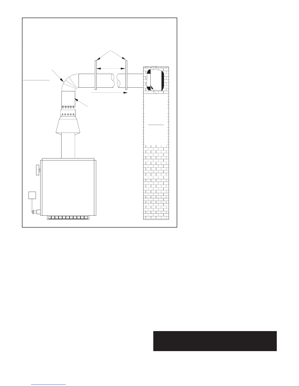
MAXIMUM
6-FT
APART
PITCH 1/4"
P
ER FOOT
S
ECURE
FLUE PIPE
TO VENT
DAMPER
USE VENT SUPPORT(S) AS REQUIRED TO PREVENT SAGGING
INSTALL
F
LUSH
WITH
I
NSIDE
CHIMNEY
LINER
SEAL
WITH
FURNACE
CEMENT
SINGLE WALL
OR TYPE B
FLUE PIPE
R
-180 = 7"
R-210 = 7"
R
-250 = 7"
R-300 = 8"
PPRROOCCEEDDUURREE CC:: IInnssttaallll fflluuee ppiippee bbeettwweeeenn vveenntt ddaammppeerr aannd
cchhiimmnneeyy ((66”” mmiinniimmuumm cclleeaarraannccee rreeqquuiirreed
bbeettwweeeenn fflluuee ppiippee aanndd ccoommbbuussttiibblleess)).
d
.
d
ing system.
2. Visually inspect the venting system for proper size and horizontal pitch and determine
there is no blockage or restriction, leakage,
corrosion and other deficiencies which could
cause an unsafe condition.
3. Insofar as is practical, close all building
doors and windows and all doors between the
space in which the appliances remaining con-
1. Seal all unused openings in common vent-
ected to the common venting system are
n
located and other spaces of the building. Turn
on clothes dryers and any appliance not connected to the common venting system. Turn on
any exhaust fans, such as range hoods and
bathroom exhausts, so they will operate at
maximum speed. Do not operate a summer
exhaust fan. Close fireplace dampers.
4. Place in operation the appliance being in-spected. Follow the lighting instructions. Ad-just thermostat so appliance will operate continuously
.
5. Test for spillage at draft hood relief opening
after 5 minutes of main burner operation. Use
the flame of a match or candle, or smoke from
cigarette, cigar or pipe.
FIGURE 1.17
AADDDDIITTIIOONNAALLVVEENNTTIINNGG RREEQQUUIIRREEMMEENNTTSS:
:
When connecting
to gas vents or chimneys, vent installations shall be in accordance with Part 7, Venting of Equipment, of the National Fuel
Gas Code, ANSI Z223.1-latest edition, or applicable provisions
of the local building codes.
Vent connectors serving appliances vented by natural draft
shall not be connected into any portion of mechanical draft systems operating under positive pressure.
When two or more appliances vent into a common flue, the
area of the common flue should be at least equal to the area of
the largest flue plus 50% of the areas of the additional flue or
vent connectors.
When an existing boiler is removed from a common venting
system, common venting system is likely to be too large for
proper venting of appliances remaining connected to it.
of removal of existing boiler
, following steps shall be followed
with each appliance remaining connected to the common vent-
ing system placed in operation, while other appliances remaining connected to common venting system are not in operation:
At time
6. After it has been determined that each ap-pliance remaining connected to common venting
system properly vents when tested as outlined
above, return doors, windows, exhaust fans,
fireplace dampers and any other gas-burning
appliance to previous conditions of use.
7. Any improper operation of the common venting system should be corrected so installation
conforms with the National Fuel Gas Code,
ANSI Z223.1-latest edition. When resizing any
portion of the common venting system, the
common venting system should be resized to
approach the minimum size as determined using the appropriate tables in Appendix G in the National Fuel Gas Code, ANSI
Z223.1-latest edition. For Canada, the provisions of CAN/CGA
B149(.1 or .2) shall apply.
AADDDDIITTIIOONNAALLCCHHIIMMNNEEYYRREEQQUUIIRREEMMEENNTTSS:
:
Chimney condition is of paramount importance for a safe and efficient boiler
installation.
All installations must include a chimney inspection
by a qualified individual or agency. Chimney construction materials must be compatible with the fuel being used.
Particular attention should be paid on all oil-to-gas conversions.
Soot may have accumulated in chimney and/or degraded chim
ney liner. Most utilities require complete chimney cleaning.
Others may require installation of new liner, spill switches or
other chimney upgrades. Check with local utility for required
safety precautions.
DDAANNGGEERR:: AAcchhiimmnneeyy wwhhiicchh ddooeess nnoott mmeeeett mmooddeerrn
ssaaffeettyy ssttaannddaarrddss wwiillll rreessuulltt iinn aa ffiirree oorr ddeeaaddllyy ccaarrbboon
mmoonnooxxiiddee ppooiissoonniinngg ooff tthhee bbuuiillddiinngg rreessiiddeennttss.
9
-
n
n
.
 Loading...