

HydroTherm PB-105, PB-120, PB-150, PB-180, PB-200 Installation And Operating Instructions Manual
...
HydroTherm
HPB9-7
P
STEA OR
ILER-
INSTALLATI
I
STRUCTI
DESIGNED AND TESTED ACCORDING TO A.S.M.E. BOILER AND PRESSURE
VESSEL CODE, SECTION IV FOR A MAXIMUM ALLOWABLE WORKING PRESSURE OF:
15 PSi STEAM OR 40 PSi WATER.
TO iNSTALLER
NOTE: READ THESE iNSTRUCTiONS CAREFULLY. THEY WiLL
SAVE YOU VALUABLE TiME WHEN ASSEMBLING THE BOILER.
OT WATE
& PE
IT
G
THESE INSTRUCTIONS TO BE LEFT WITH THE BOILER FOR REFERENCE PURPOSES.
CONSUMER, RETAIN THESE INSTRUCTIONS FOR FUTURE REFERENCE PURPOSES.
IN UNITED STATES: 260 NORTH ELM ST., WESTFIELD, MA 01085 • (413) 564-5515 FAX (413) 568-9613
IN CANADA: 7555 TRANMERE DRIVE, MISSlSSAUGA, ONTARIO L5S 1L4 • (905) 672-2991 FAX (905) 672-2883
HydroTherm _
www.hydrotherm.com

Page 2 PB SERIES BOILER INSTALLATION AND OPERATING INSTRUCTIONS
CONTENTS
General ....................................................................... 2
Codes, Rules and Regulations ................................... 2
Boiler Location ............................................................ 3
Chimney and Breeching ............................................. 3
Combustion and Ventilation ........................................ 3
Inspection ................................................................... 4
Jacket Assembly ......................................................... 4
Cleanout Cover Plates ................................................ 4
Boiler Trim ......................................... (water)5, (Steam)11
Thermostat and Limit Controls .......... (water)5, (Steam)12
Piping Connections ............................ (water)6, (Steam)11
Circulators .................................................................. 8
Domestic Hot Water Heaters ............. (water)9, (Steam)15
Filling the System .............................. (water)8, (Steam)14
Boiler Maintenance ...................... (water)9-10, (steam)15
Special Boiler Cable Installation ............................... 16
Replacement Parts ................................................... 19
Start-Up Checklist .................................................... 21
Burner Specifications ............................................... 22
GENERAL
The PB boiler-burner unit is a wet-base, vertical flue,
low pressure, sectional, cast iron steam or hot water
heating boiler. It is rated for natural draft firing with
-0.02" W.C. over the fire draft.
The PB boiler is offered in 2 different configurations:
1 - Packaged boiler with "burner in the box" shipped
separately.
2 - Packaged boiler with burner mounted and wired.
CODES, RULES AND REGULATIONS
The installation of the boiler, the burner, wiring, controls
and fuel piping must be done in accordance with the
requirements of the local authorities having jurisdiction.
In the absence of local requirements, the following
codes apply:
ANSI/NFPA31 - "Installation of Oil Burning Equipment"
ANSI/NFPA70- "National Electrical Code"
In Canada the following codes apply:
CSA STD. B149 - Latest Edition.
"Installation Code For Oil Burning Equipment."
CSA STD. C22.2 No. 0 - Latest Edition.
"General Requirements - Canadian Electrical Code
Part I1."
The ports between sections are provided with a special
hydronic seal which is resistant to petroleum products.
The flue gas seal between sections is accomplished by
the use of fiberglass rope rated at 1000 ° R
Packaged units are hydrostatically tested for the maxi-
mum working pressures.
An insulated metal jacket is furnished to both enhance
the units looks and to minimize any heat loss. A
full access cleanout cover for cleaning vertical flue
passages is on the left hand side of the boiler and is
accessible by removing the left hand cleanout access
jacket panel.
All completed boilers shall satisfactorily pass the
hydrostatic tests as prescribed by A.S.M.E., Code
Section IV.
,
Steam Boilers - The assembled boiler shall be
subjected to a hydrostatic test of not less than 45
psig.
,
Water Boilers - The assembled boiler shall be
subjected to a hydrostatic test pressure of 60 psig.
,
The required test shall not exceed the test pressure
by more than 10 psig.
PBSERIESBOILERINSTALLATIONANDOPERATINGINSTRUCTIONS Page3
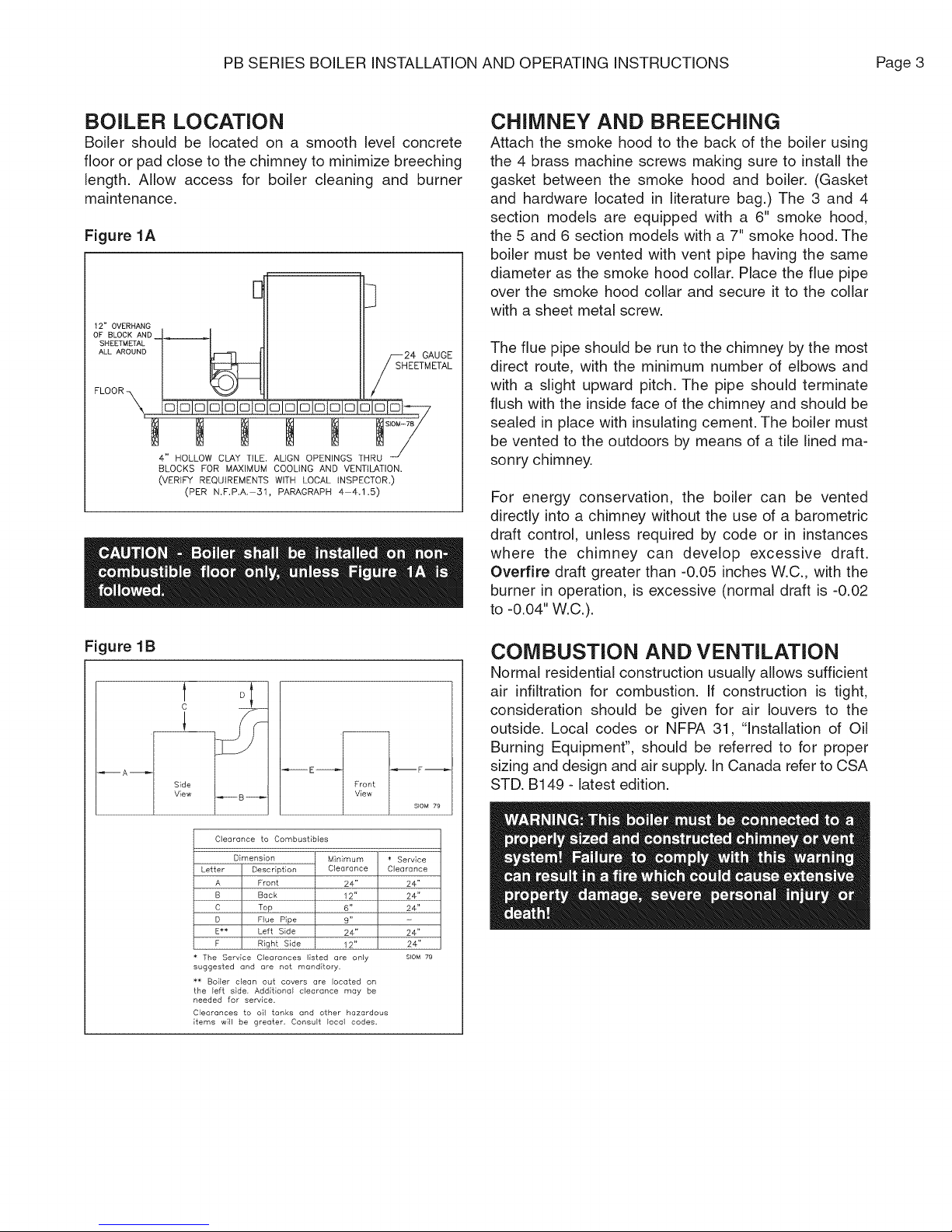
BOILER LOCATION
Boibr should be located on a smooth level concrete
floor or pad close to the chimney to minimize breeching
length. Allow access for boiler cleaning and burner
maintenance.
Figure 1A
12" OVERHANG
OF BLOCK AND
SHEETMETAL
ALL AROUND
4" HOLLOW CLAY TILE. ALIGN OPENINGS THRU
BLOCKS FOR MAXIMUM COOLING AND VENTILATION.
(VERIFY REQUIREMENTS WITH LOCAL INSPECTOR.)
(PER N.F.P.A.-31, PARAGRAPH 4-4.1.5)
///_H24 GAUGE
EETMETAL
CHIMNEY AND BREECHING
Attach the smoke hood to the back of the boiler using
the 4 brass machine screws making sure to install the
gasket between the smoke hood and boiler. (Gasket
and hardware located in literature bag.) The 3 and 4
section models are equipped with a 6" smoke hood,
the 5 and 6 section models with a 7" smoke hood. The
boiler must be vented with vent pipe having the same
diameter as the smoke hood collar. Place the flue pipe
over the smoke hood collar and secure it to the collar
with a sheet metal screw.
The flue pipe should be run to the chimney by the most
direct route, with the minimum number of elbows and
with a slight upward pitch. The pipe should terminate
flush with the inside face of the chimney and should be
sealed in place with insulating cement. The boiler must
be vented to the outdoors by means of a tile lined ma-
sonry chimney.
For energy conservation, the boiler can be vented
directly into a chimney without the use of a barometric
draft control, unless required by code or in instances
where the chimney can develop excessive draft.
Overfire draft greater than -0.05 inches W.C., with the
burner in operation, is excessive (normal draft is -0.02
to -0.04" W.C.).
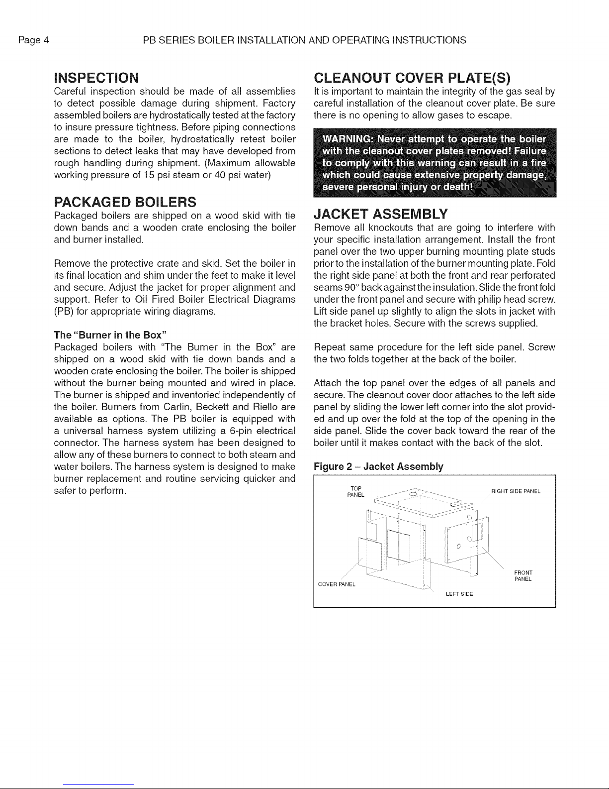
Figure 1B
Clearance to Combustibles
Dimension Minimum * Service
Letter Description Clearance Clearance
A Front 24" 24"
B Back 12" 24"
C Top 6" 24"
D Flue Pipe 9"
E** Left Bide 24" 24"
F Right Side 12" 24"
The Service Clearances listed are only SIOM 79
suggested and ore not manditory.
• * Boiler clean out covers are located on
the left side, Additional clearance may be
needed for service.
Clearances to oil tanks and other hazardous
items will be greeter. Consult local codes.
COMBUSTION AND VENTILATION
Normal residential construction usually allows sufficient
air infiltration for combustion. If construction is tight,
consideration should be given for air louvers to the
outside. Local codes or NFPA 31, "Installation of Oil
Burning Equipment", should be referred to for proper
sizing and design and air supply. In Canada refer to CSA
STD. B149 - latest edition.
Page4 PBSERIESBOILERINSTALLATIONANDOPERATINGINSTRUCTIONS
INSPECTION
Careful inspection should be made of all assemblies
to detect possible damage during shipment. Factory
assembled boilers are hydrostatically tested at the factory
to insure pressure tightness. Before piping connections
are made to the boiler, hydrostatically retest boiler
sections to detect leaks that may have developed from
rough handling during shipment. (Maximum allowable
working pressure of 15 psi steam or 40 psi water)
PACKAGED BOILERS
Packaged boilers are shipped on a wood skid with tie
down bands and a wooden crate enclosing the boiler
and burner installed.
Remove the protective crate and skid. Set the boiler in
its final location and shim under the feet to make it level
and secure. Adjust the jacket for proper alignment and
support. Refer to Oil Fired Boiler Electrical Diagrams
(PB) for appropriate wiring diagrams.
The "Burner in the Box"
Packaged boilers with "The Burner in the Box" are
shipped on a wood skid with tie down bands and a
wooden crate enclosing the boiler. The boiler is shipped
without the burner being mounted and wired in place.
The burner is shipped and inventoried independently of
the boiler. Burners from Carlin, Beckett and Riello are
available as options. The PB boiler is equipped with
a universal harness system utilizing a 6-pin electrical
connector. The harness system has been designed to
allow any of these burners to connect to both steam and
water boilers. The harness system is designed to make
burner replacement and routine servicing quicker and
safer to perform.
CLEANOUT COVER PLATE(S)
It is important to maintain the integrity of the gas seal by
careful installation of the cleanout cover plate. Be sure
there is no opening to allow gases to escape.
JACKET ASSEMBLY
Remove all knockouts that are going to interfere with
your specific installation arrangement. Install the front
panel over the two upper burning mounting plate studs
prior to the installation of the burner mounting plate. Fold
the right side panel at both the front and rear perforated
seams 90° back against the insulation. Slide the front fold
under the front panel and secure with philip head screw.
Lift side panel up slightly to align the slots in jacket with
the bracket holes. Secure with the screws supplied.
Repeat same procedure for the left side panel. Screw
the two folds together at the back of the boiler.
Attach the top panel over the edges of all panels and
secure. The cleanout cover door attaches to the left side
panel by sliding the lower left corner into the slot provid-
ed and up over the fold at the top of the opening in the
side panel. Slide the cover back toward the rear of the
boiler until it makes contact with the back of the slot.
Figure 2 - Jacket Assembly
TOP RIGHT SIDE PANEL
PANEL
COVER PANEL
LEFT SIDE
FRONT
PANEL
PB SERIES BOILER INSTALLATION AND OPERATING INSTRUCTIONS Page 5
BOIL ERS
Figure 4 - Relief Valve Installation
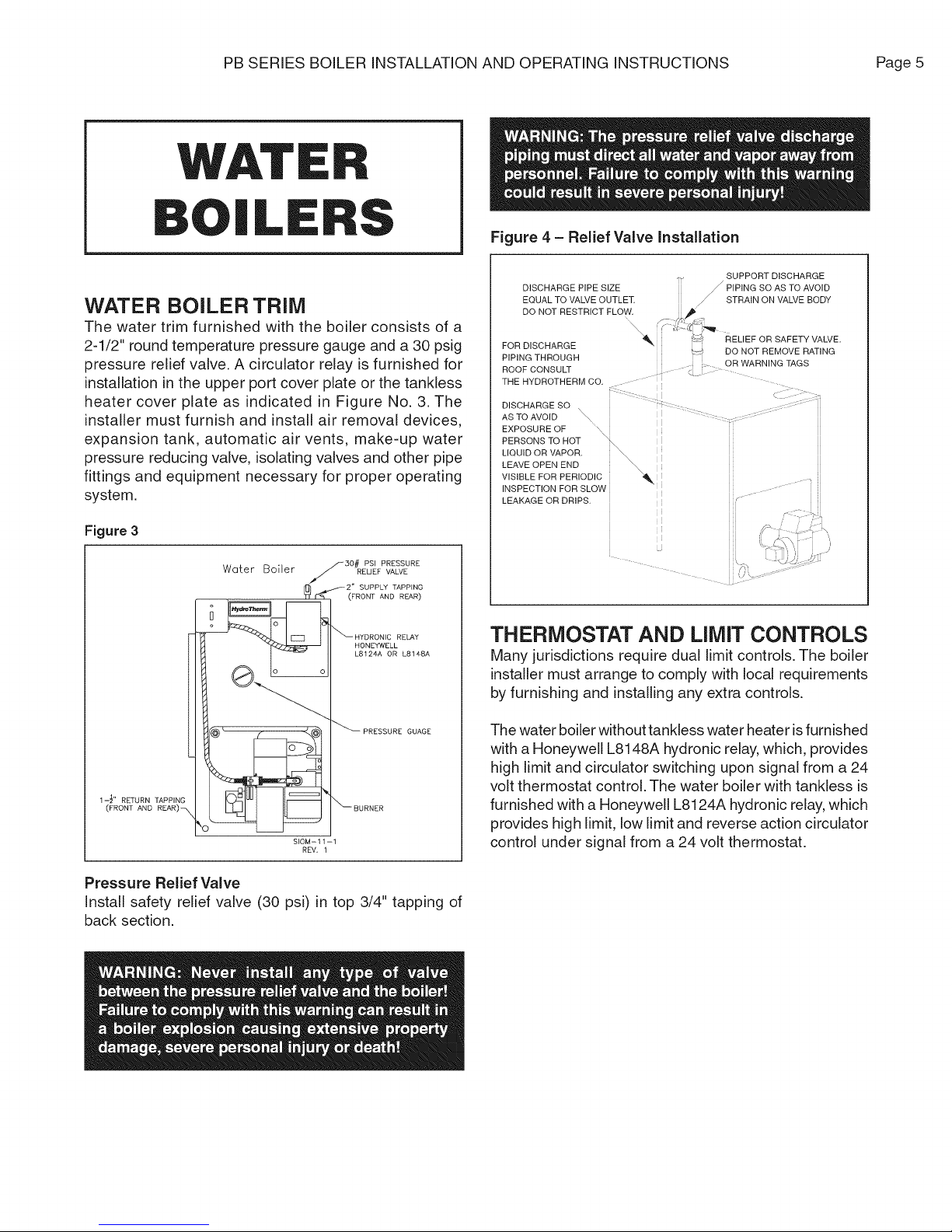
WATER BOILER TRIM
The water trim furnished with the boiler consists of a
2-1/2" round temperature pressure gauge and a 30 psig
pressure relief valve. A circulator relay is furnished for
installation in the upper port cover plate or the tankless
heater cover plate as indicated in Figure No. 3. The
installer must furnish and install air removal devices,
expansion tank, automatic air vents, make-up water
pressure reducing valve, isolating valves and other pipe
fittings and equipment necessary for proper operating
system.
Figure 3
Water Boiler
30# PSI PRESSURE
RELIEF VALVE
_i} _2" SUPPLY TAPPING
(FRONT AND REAR)
_HYDRONIC RELAY
HONEYWELL
L8124A OR L8148A
DISCHARGE PIPE SIZE _ PIPING SO AS TQ AVOID
EQUAL TO VALVE OUTLET //STRAIN ON VALVE BODY
DO NOT RESTRICT FLOW. ,_
FOR DISCHARGE
PIPING THROUGH . OR WARNING TAGS
ROOF CONSULT ....
THE HYDROTHERM CO.
DISCHARGE SO t: ............. ................................
AS TO AVOID _ ........................................................
EXPOSUREOF ....\
PERSONS TO HOT \:
LIQUIDORVAPOR.
LEAVE OPEN END
VISIBLE FOR PERIODIC_
INSPECTION FOR SLOW
LEAKAGE OR DRIPS.
f- i/b ,: ,
\
_i_ _'_ RELIEF OR SAFETY VALVE.
SUPPORT DISCHARGE
t_ DO NOT REMOVE RATING
THERMOSTAT AND LIMIT CONTROLS
Many jurisdictions require dual limit controls. The boiler
installer must arrange to comply with local requirements
by furnishing and installing any extra controls.
_PRESSURE GUAGE
1-_1' RETURN TAPPING
(FRONT AND
SIOM-11-1
REV,
_BURNER
Pressure Relief Valve
Install safety relief valve (30 psi) in top 3/4" tapping of
back section.
The water boiler without tankless water heater isfurnished
with a Honeywell L8148A hydronic relay, which, provides
high limit and circulator switching upon signal from a 24
volt thermostat control, The water boiler with tankless is
furnished with a Honeywell L8124A hydronic relay, which
provides high limit, low limit and reverse action circulator
control under signal from a 24 volt thermostat,
Page6 PBSERIESBOILERINSTALLATIONANDOPERATINGINSTRUCTIONS
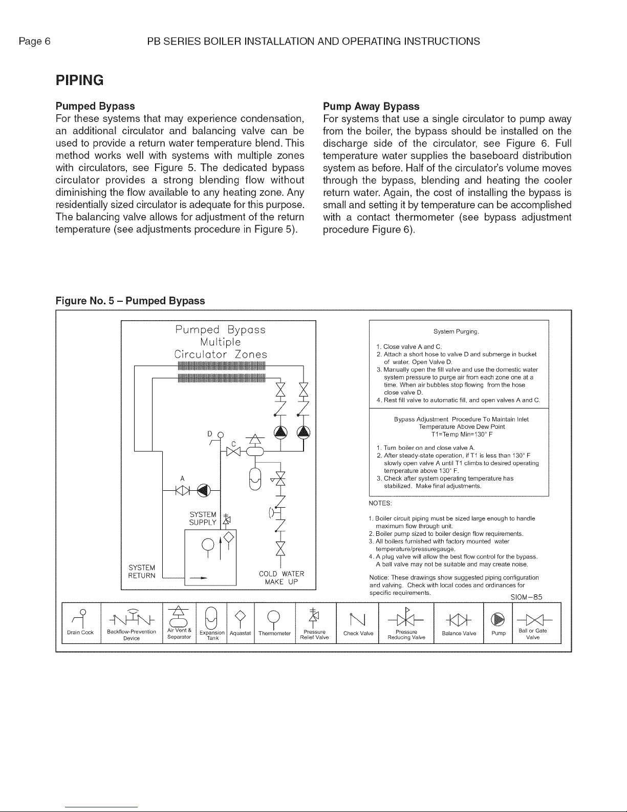
PIPING
Pumped Bypass
For these systems that may experience condensation,
an additional circulator and balancing valve can be
used to provide a return water temperature blend. This
method works well with systems with multiple zones
with circulators, see Figure 5. The dedicated bypass
circulator provides a strong blending flow without
diminishing the flow available to any heating zone. Any
residentially sized circulator is adequate for this purpose.
The balancing valve allows for adjustment of the return
temperature (see adjustments procedure in Figure 5).
Figure No. 5 - Pumped Bypass
Pumped Byposs
Multiple
CirculQtor Zones
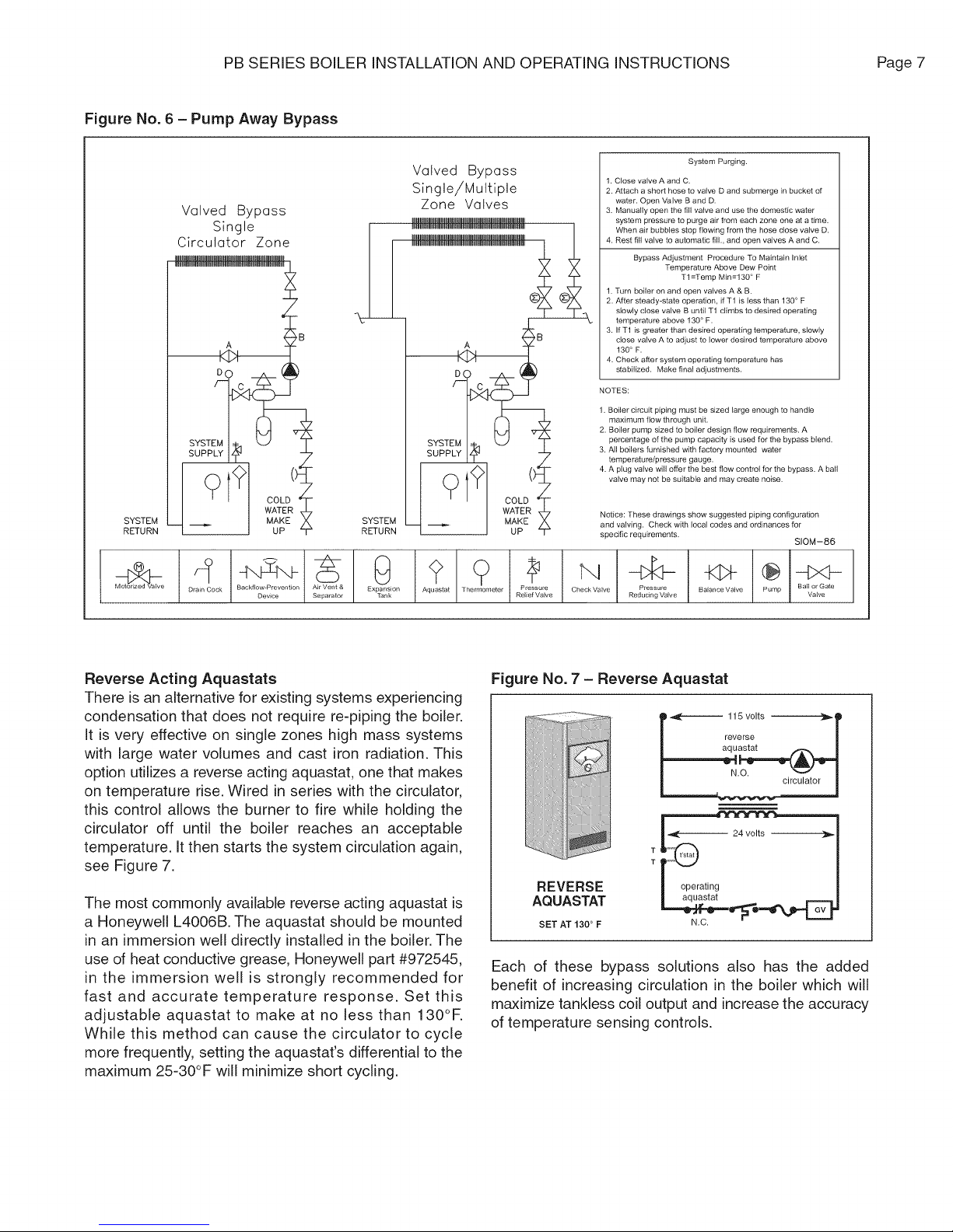
Pump Away Bypass
For systems that use a single circulator to pump away
from the boiler, the bypass should be installed on the
discharge side of the circulator, see Figure 6. Full
temperature water supplies the baseboard distribution
system as before. Half of the circulator's volume moves
through the bypass, blending and heating the cooler
return water. Again, the cost of installing the bypass is
small and setting it by temperature can be accomplished
with a contact thermometer (see bypass adjustment
procedure Figure 6).
System Purging.
1. Close valve A and C.
2. Attach a short hose to valve D and submerge in bucket
of waten Open Valve D.
3. Manually open the fill valve and use the domestic water
system pressure to purge air from each zone one at a
time. When air bubbles stop flowing from the hose
close valve D.
4. Rest fill valve to automatic fill, and open valves A and C.
I
SI 'STD
.qU RI
ra]n_C°
D ck Backflow-Prevention
Device
A
COLD WATER
MAKE UP
_" 0 <_ (_ Z-_ CheckValve
A: pVaeran_o&r Ex PTans_on Aquastat Th ...... tar RPrie_r ee
Bypass Adjustment Procedure To Maintain lnlet
Te mperature Above Dew Point
Tl=Temp Min=130 ° F
1. Turn boiler on and close valve A.
2. After steady_state operation, if T1 is less than 130 ° F
slowly open valve A until T1 climbs to desired operating
temperature above 130 ° F.
3. Check after system operating temperature has
stabilized. Make final adjustments.
NOTES:
1. Boiler circuit piping must be sized large enough to handle
maximum flow through unit.
2. Boiler pump sized to boiler design flow requirements.
3. All boilers furnished with factory mounted water
temperature/pressuregauge.
4. A plug valve will allow the best flow control for the bypass.
A ball valve may not be suitable and may create noise.
Notice: These drawings show suggested piping configuration
and valving. Check with local codes and ordinances for
specific requirements. S10M-85
Pressure Balance Valve Ball or Gate
Reducing Valve Valve
PB SERIES BOILER INSTALLATION AND OPERATING INSTRUCTIONS Page 7
Figure No. 6 - Pump Away Bypass
SYSTEM
RETURN
Valved Bypass
Single
Circulator Zone
A B
D
C
SUPPLY IZ_ ?
.......... DeP rceeV........
Valved Bypass
Single/Multiple
Zone Valves
D
C
A
SUPPLY IZ_
RETURN
AIrV_enta _ E _ .... Q"_astat -The21ete Pr es_a re _'_
S_p ...... X_an_ u r Rel e_Jve C ......... Reduc,ng .....
1. Close valve A and C.
2. Attach a short hose to valve D and submerge in bucket of
water. Open Valve B and D.
3. Manually open the fill valve and use the domestic water
system pressure to purge air from each zone one at a time.
When air bubbles stop flowing from the hose close valve D.
4. Rest fill valve to automatic fill., and open valves A and C.
Bypass Adjustment Procedure To Maintain Inlet
1. Turn boiler on and open valves A & B.
\
2. After steady-state operation, if T1 is less than 130 ° F
slowly close valve B until T1 climbs to desired operating
temperature above 130 ° F.
3. If T1 is greater than desired operating temperature, slowly
close valve A to adjust to lower desired temperature above
130 ° F.
4. Check after system operating temperature has
stabilized. Make final adjustments.
NOTES:
1. Boiler circuit piping must be sized large enough to handle
maximum flow through unit.
2. Boiler pump sized to boiler design flow requirements. A
percentage of the pump capacity is used for the bypass blend.
3. All boilers furnished with factory mounted water
temperature/pressure gauge.
4. A plug valve will offer the best flow control for the bypass. A ball
valve may not be suitable and may create noise.
Notice: These drawings show suggested piping configuration
and valving. Check with local codes and ordinances for
specific requirements.
System Purging.
Temperature Above Dew Point
Tl=Temp Min=130 ° F
Balance Valve Pump " Valve"
S10M-86
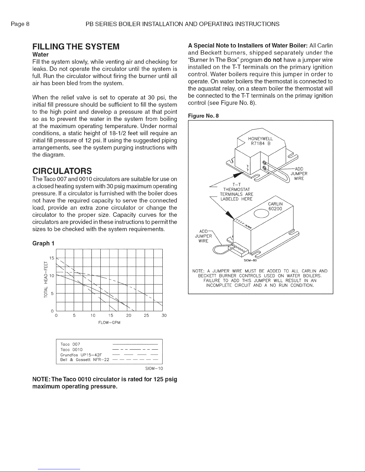
Reverse Acting Aquastats
There is an alternative for existing systems experiencing
condensation that does not require re-piping the boiler.
It is very effective on single zones high mass systems
with large water volumes and cast iron radiation. This
option utilizes a reverse acting aquastat, one that makes
on temperature rise. Wired in series with the circulator,
this control allows the burner to fire while holding the
circulator off until the boiler reaches an acceptable
temperature. It then starts the system circulation again,
see Figure 7.
The most commonly available reverse acting aquastat is
a Honeywell L4006B. The aquastat should be mounted
in an immersion well directly installed in the boiler. The
use of heat conductive grease, Honeywell part #972545,
in the immersion well is strongly recommended for
fast and accurate temperature response. Set this
adjustable aquastat to make at no less than 130°R
While this method can cause the circulator to cycle
more frequently, setting the aquastat's differential to the
maximum 25-30°F will minimize short cycling.
Figure No. 7 - Reverse Aquastat
115 volts ---}_
_._______reverse
N.OO. cJrc-_lator 1
T _
REVERSE
AQUASTAT
SET AT 130 ° F
Each of these bypass solutions also has the added
benefit of increasing circulation in the boiler which will
maximize tankless coil output and increase the accuracy
of temperature sensing controls.
Page8 PBSERIESBOILERINSTALLATIONANDOPERATINGINSTRUCTIONS
FILLING THE SYSTEM
Water
Fill the system slowly, while venting air and checking for
leaks. Do not operate the circulator until the system is
full. Run the circulator without firing the burner until all
air has been bled from the system.
When the relief valve is set to operate at 30 psi, the
initial fill pressure should be sufficient to fill the system
to the high point and develop a pressure at that point
so as to prevent the water in the system from boiling
at the maximum operating temperature. Under normal
conditions, a static height of 18-1/2 feet will require an
initial fill pressure of 12 psi. If using the suggested piping
arrangements, see the system purging instructions with
the diagram.
CIRCULATORS
The Taco 007 and 0010 circulators are suitable for use on
a closed heating system with 30 psig maximum operating
pressure. If a circulator is furnished with the boiler does
not have the required capacity to serve the connected
load, provide an extra zone circulator or change the
circulator to the proper size. Capacity curves for the
circulators are provided in these instructions to permit the
sizes to be checked with the system requirements.
A Special Note to Installers of Water Boiler: All Carlin
and Beckett burners, shipped separately under the
"Burner In The Box" program do not have a jumper wire
installed on the T-T terminals on the primary ignition
control. Water boilers require this jumper in order to
operate. On water boilers the thermostat is connected to
the aquastat relay, on a steam boiler the thermostat will
be connected to the T-T terminals on the primay ignition
control (see Figure No. 8).
Figure No. 8
JUMPER
WIRE
T-T
THERMOSTAT
TERMINALS ARE
Graph 1
15
B
I
21o
:z
u
_<
oS
5 10 15 20 25
Toco 007
Toco 00t0
Grundfos UP15-42F
Belt & Gossett NFR-22
"\ _ --
3O
FL0W-GPM
SIOM-IO
NOTE: The Taco 0010 circulator is rated for 125 psig
maximum operating pressure.
WlRE_
SIOM-80
NOTE: A JUMPER WIRE MUST BE ADDED TO ALL CARLIN AND
BECKETT BURNER CONTROLS USED ON WATER BOILERS.
FAILURE TO ADD THIS JUMPER WILL RESULT IN AN
iNCOMPLETE CIRCUIT AND A NO RUN CONDITION,
 Loading...