

HydroTherm OM 06, OM 08, OM 07, OM 09, OM 11 Installation, Operation And Maintanance Manual
...Page 1

Oil / Gas Fired Boiler
Cast iron
Triple -Pass Design
378 kW to 930 kW
Page 2

CONTENTS Page
INTRODUCTION 3
GUARANTEE TERMS 4
GENERAL WARNINGS 5
GENERAL CHARACTERISTICS OF OM SERIES BOILERS 7
OM SERIES CAST IRON BOILER - TECNICAL DATA 8
OM SERIES CAST IRON BOILER - DIMENSIONS 10
BOILER ROOM SETTINGS AND BOILER PLATFORM DIMENSIONS 12
PLUMBING INSTRUCTIONS 13
A SAMPLE PLUMBING DIAGRAM FOR OM SERIES CAST IRON BOILERS 14
THE MEANING OF THE SYMBOLS USED IN THE DIAGRAM 15
DIAGRAM OF A SAMPLE SINGLE BOILER HEATING CIRCUIT WITH WATER HEATER 16
WATER CIRCULATION PRINCIPAL 17
INSTRUCTIONS ABOUT FLUE 18
INSTRUCTIONS FOR CONNECTING THE FUEL TANK 19
BOILER CONTROL PANELS 20
ELECTRICAL DIAGRAMS 21
CAST IRON SECTIONS WITH HIGH EFFICIENCY 3 DRAUGHT DESIGN 22
OPERATING INSTRUCTIONS 23
LOADING AND UNLOADING BOILER WATER,INSTRUCTIONS FOR PRODUCT DISPOSAL 24
OM SERIE CAST IRON BODY -BOILER CABIN PARTS LIST 25
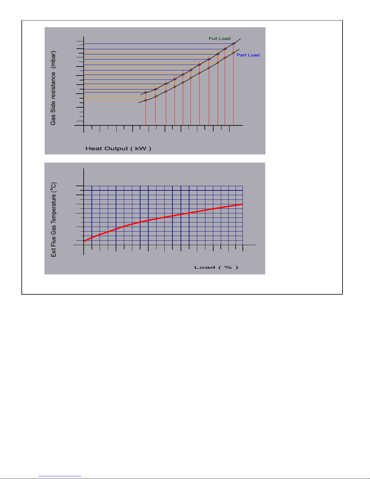
DIAGRAMS - GAS SIDE RESISTANCE , EXIT FLUE GAS RESISTANCE 26
IMPORTANT INSTRUCTIONS ABOUT BOILER ROOM 28
BOILER ROOM AIRING 29
CHECKINGS AND STARTING THE BOILER 31
FAILURE FIRST CONTROL 32
CARE INSTRUCTIONS , PACKING 34
CLEANING THE BOILER 35
BURNER DOOR AND BURNER CONNECTION 36
BURNER CONNECTION FLANGE SIZES 37
INTRODUCTION
In this manual you will find the instructions for three pass cast iron boilers suitable for both gas
and liquid fuel.OM series hot water boilers and related informaton for installation,operation and maintanance of the boiler. For high efficiency and proper working conditions please read this manual carefully.
For more information please check the product catalog or get in touch with technical services.
Please do not touch or remove any parts of the boiler for starting,adjusting or repairing the boiler except
the processes written in this manual
Please call services and technical officials for installing the boiler.
Our licensed frenchisers and services will
g
ive you instructions about working principals,conditions and
care instructions after installing and starting the boiler.
And our professionals will be glad to answer all your questions at any time.
licensed services are in your service all kind of problems and questions. You may find the contact
informations in the licensed services manual which will be given to you with the boiler.
First of all we'd like to thank you for choosing our cast iron boilers.
Page 3

GUARENTEE TERMS
*In the terms of obeying the instructions,warnings, points in this manual and the standards in charge
(EN norms and directives must be applied if mentioned standards are not in use.) cast body is under
5 (five) and other parts are under 2 (two) years guarantee.
Our company is responsible for repairing or renewing if the following conditions are available.
*Guarantee Document must be filled by the franchiser that you have bought the boiler and must be
send to
*Assembling and installing faults and problems, problems that will be occured because of wrong upkee
ping
and working are not under guarantee.Problems related to lime coating or/and any other ma-
terials coatin
g
and corrosion on the heat transfer units of the boiler are not under guarantee conditions.
*Minimum life of these kind of
p
roducts is mentioned as 15 (fifteen) years by the minister of industry
and commerce. Manufacturer and sales companies are to suplly all spare parts and services to the
clients in this period.
! The problems happened by the following mentioned issues are out of guarantee conditions
! Boiler without guarantee document
! Boiler fixed,repaired or adjusted by unauthorized services
! Boilers with rong type selection, wrong installing and assembling, boilers used wrong conditions and
out of aim.
! Problems occured while transportation,stocking or problems occured under atmospheric conditions.
! The problems occured by physical or chemical effects.
! Wrong fuel selection and the problems occured by fuel conditions,
! Wrong installation or connection fo the boiler to water and other plumbing systems.
! Weak flue (gas output) system
! The problems occured by scratching,touching to control and safety systems of the boiler.
! Cold water load while the boiler is hot
! Starting the boiler without water or required water in it.
GENERAL WARNINGS
!
ted to use out of it's aim of use.
!
!
on.
!
future repairing operations.
! Starting and first operation of the boiler must be made by authorized technicians.
!
!
!
! The periodical controls of the boiler and the burner must be done. If not, the boiler can lose efficiency
and the fuel amount used can increase.
! The ca
p
acity choice of the boiler must be made according to the projects that prepared properly in the
terms of related standards. If not the the efficiency will be low.
! OM series boilers are produced for heating only. For heating the sanitary water another equipment
such as water heater or heat exchanger is needed.And for proper efficiency in this operation,correct water heater or heat exchanger must be selected.
culation pumps, must be started 1 -2 times per month for 5 minutes. (The water with chalk can cause
problems if the pump is not used for long time period.)
In summer months, when the boiler is off for a long term, for preventing probable problems with cir-
In the assembling of the boiler; there must be a proper and safe concrete platform for to put the boiler
surely be started while adding water to the system.If not,the sections may crack.
The electric must be cut off from the main shelter/fuse as the boiler is in repair,service or cleaning.
If the boiler will be kept off for a long time the electric system must be shut down from the main fuse.
OM series cast iron boilers are designed for working with hot water heating and/or hot water plumbing
Do not add or pump water to the boiler or plumbing system as it is working and hot.For adding water to
the boiler or to the systen please wait for water temperature to come 40ºC. Circulation pump must
of the boiler should also be made by licensed services, if not the risk of damage is high.
and produced with the proper technology and materials suitable to this design.This desing is restric-
OM series boilers are delievered as sections and services assemble the boilers in the operation
area. The assembling of the boiler must be made by technical services. Removing or re-assembling
In the assembling of the boiler,an empty space must be left from sides for safety requirements and for
Page 4

! OM series boilers are delivered without burners. For suitable burner selection
p
lease get in touch with
technicians. Suitable burners must be selected for takin
g
high efficiency.
! If the boiler is sto
pp
ed automatically because of over heating do not add cold water to the boiler for
restartin
g
. In this case wait for the boiler to cool down and re- try starting.If it does not start please
g
et in contact with technical services.
! In cleanin
g
, repair and other care operations the original spare parts which approved and manufactured
b
y
manufacturer must be used.
! The
p
eriodical and yearly controls of the boiler must be done properly and on time.Natural gas is a clean
fuel and doesn't make a lot of dirt in the boiler.But the boilers that li
q
uid fuels are used as fuels are much
more easil
y g
et dirt. Controls and care operations of the boiler is needed for keeping high efficiency and
lon
g
life of the boiler.
! Re
p
airing and periodical controls of OM series boilers require profession.In this manual the responsibilities
and re
q
uired information for users of the boiler is declared. Besides these declared operations, boiler
must not be started b
y
a person rather than the user or one our technicians.Please do not try to make
ad
j
ustment or do not touch any parts of the boilers.
! The electric of the burner and the boiler is su
pp
lied by city electric network.In this case the elecric and
li
g
hting systems of the boiler room, burner and boiler electrical connections, grounding line of control
p
anel and boiler must be made by professionals under the required and related standards.
! In this manual
y
ou will find informations only for the boilers. Please do not forget to get the instruction
manual of the burner that
y
ou purchase from the manufacturer of it. Burner is not delivered with the
boiler. In this case we do not give any guarantee for the burner that you purchase. Please get th
e
q
uarantee certificate for the burner from your supplier.
! Please be sure that the front door
(
burner door) for the boiler is strictly closed and burner connections
are
prop
erly made as the boiler is working.
GENERAL CHARACTERISTICS OF RS SERIES BOILERS
OM series boilers are, blowing burner, cast iron sectioned, between the capacities 378 – 930 kW with
proper burner connection, works with gas or liquid fuel in 11 different ( 6 – 16 sections) type.
OM series boilers operating pressure is 6 bar maximum, and working temperature is 90 °C maximum.
In OM series boilers,heat transfer surface areas are increased by the special wings in the burning room
and chimney ways.This inceases the high heat transfer ability of cast iron boiler to the maximum level.
OM series boilers are cast iron sectioned boilers.This brings easy assembling and easy capacity increasing
by adding sections to the boiler. The transportation and set up of the boiler is easy because boiler is
assembled in boiler rooms It is easily to carry or shift position without breaking walls etc.
OM series boilers are casted with special alloy, which is durable for heat extansions and changes, EN GJ
L
200. They are long life boilers according to this special cast iron alloy.
With the help of horizontal and three pass specially designed sections burning gases pass three times in
the boiler and transmits burning energy to the water inside the sections at high level.
OM series boilers are high efficiency boilers. ( According to the fuel bottom heating value % 91 – 93 ).
With this high efficiency and perfect isolation more energy is gained with less fuel. Heat loses are
minimized on OM series boilers.
By appropriate burning room, heat transfer surface, turbulator, collector and isolation high heat transfer
and optimum flue gas emition results are provided.
Boiler sections are delivered as assembled or not assembled according to the boiler room specifications
and dimensions.In not assembled deliveries, sections and assembling aparats are delivered on a pallet,
cabins,isolation and other elements are delivered in a box. technicians make the assembling of the
boiler.
Delivery Conditions
Page 5
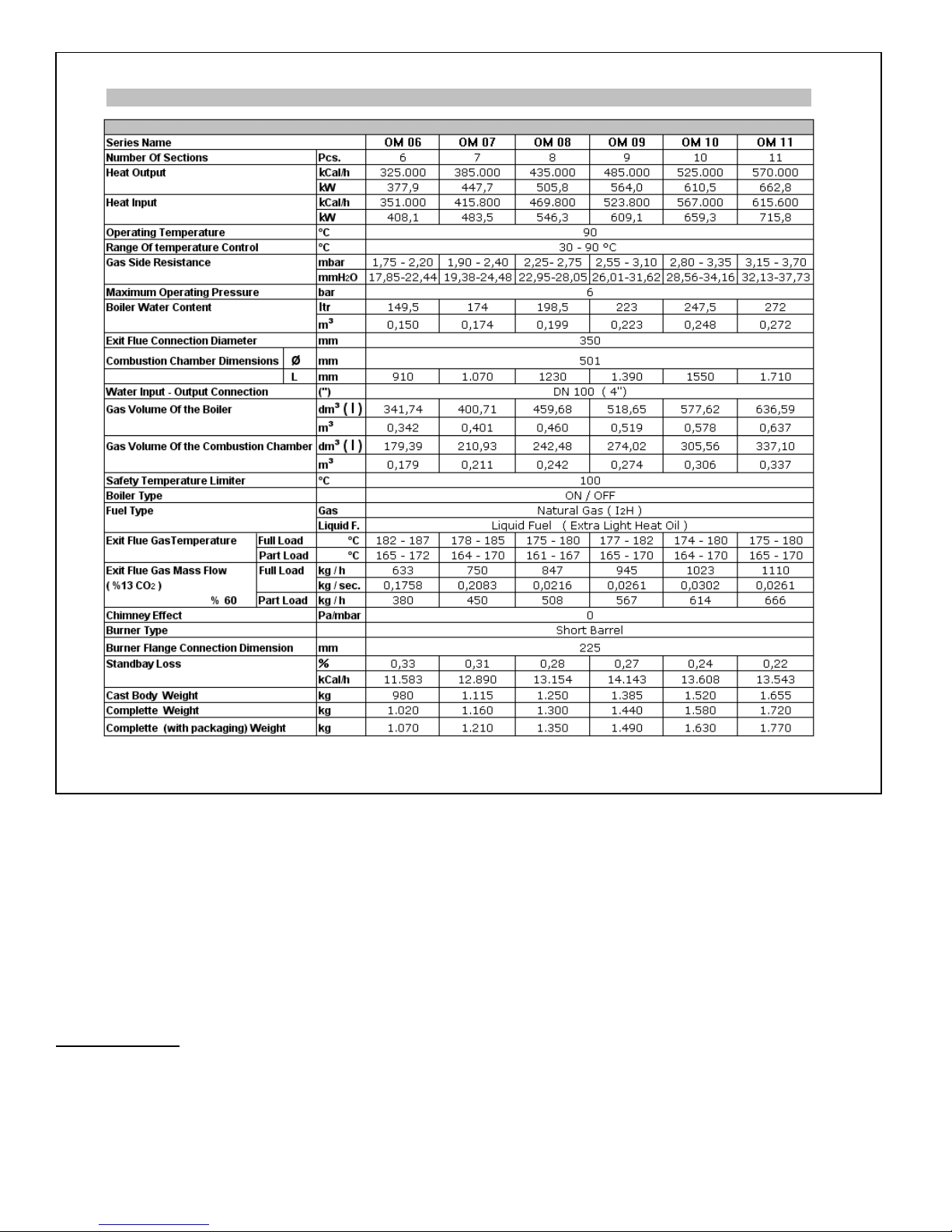
OM SERIES CAST IRON BOILER - TECNICAL DATA . I
Page 6
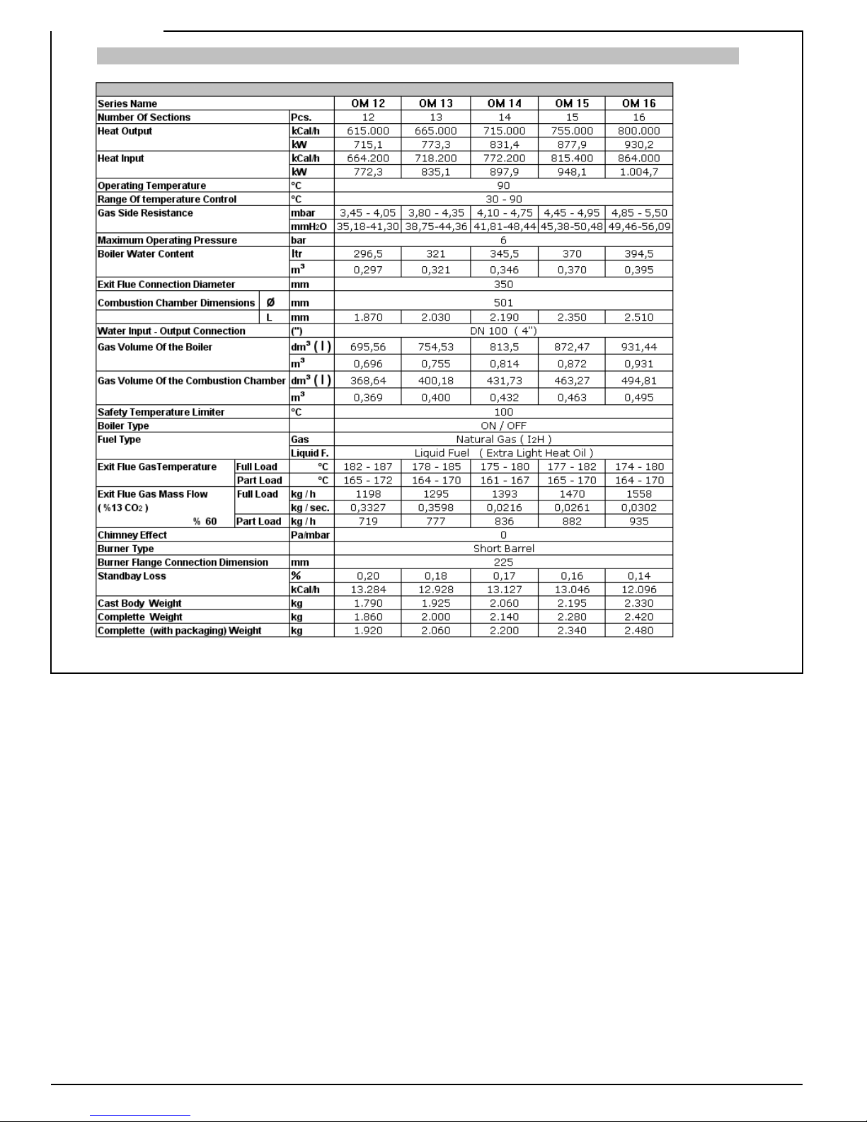
OM SERIES CAST IRON BOILER - TECNICAL DATA . II
Page 7
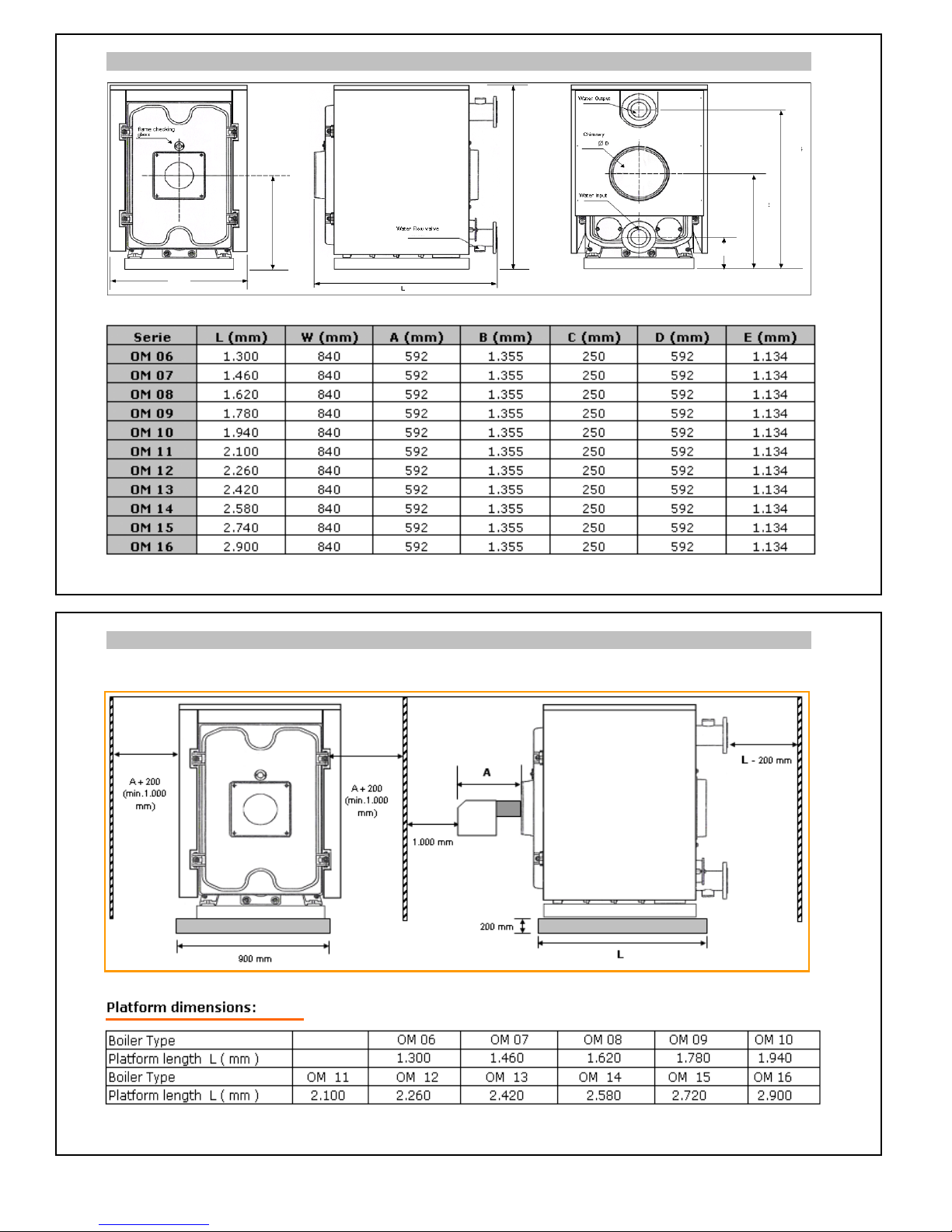
OM SERIES CAST IRON BOILER DIMENSIONS
BOILER ROOM SETTINGS AND BOILER PLATFORM DIMENSIONS
W
B
C
D
E
Page 8
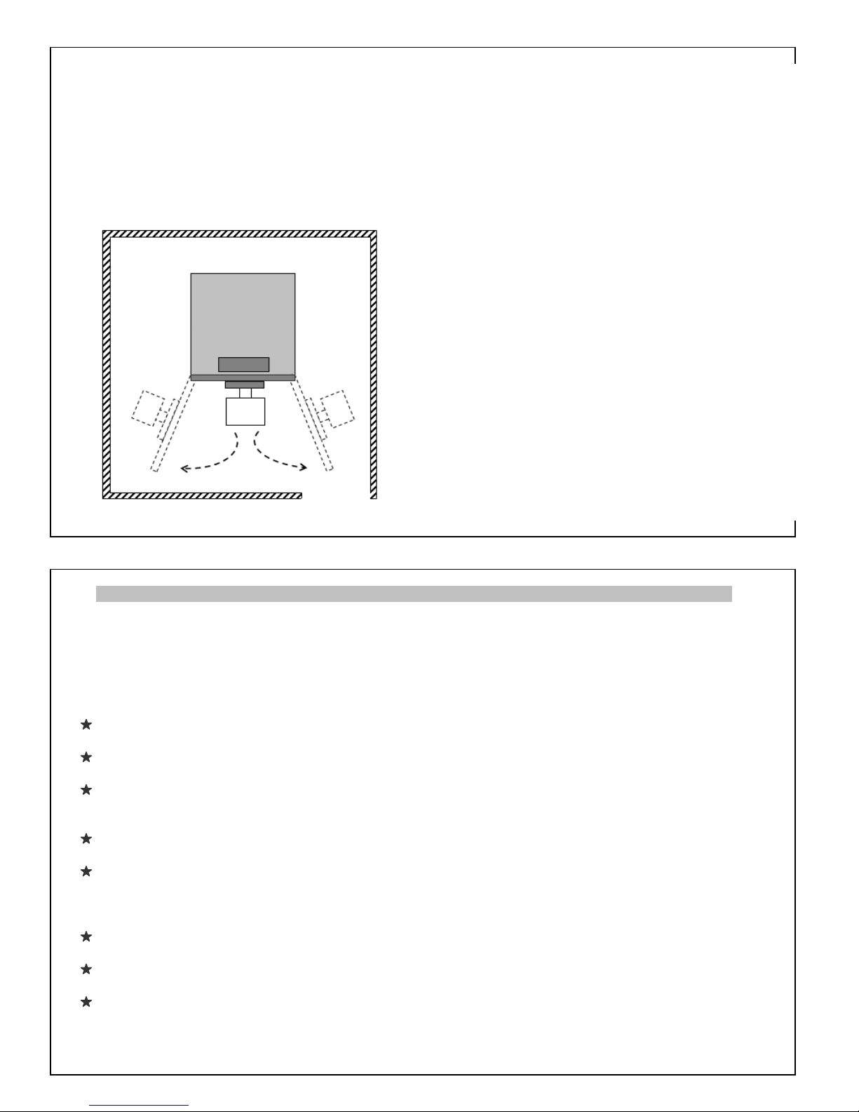
The measurements of the boiler room and the empty spaces must be arranged properly for future
assembling repairing, re-assembling, burner connecting issues.
* The concret platform must be in the mentioned dimensions.
* Concrete platfrom must not be coated with slipper materials such as ceramics etc.
* If sound izolaton will be made,first do the sound izolation than make the concrete for platform.
* Platfroms must be made of BS 25 concrete and scales.
* In OM series boilers burner doors can be opened to
both sides. According to this the required empty
spaces for the both sides are given equal.
(min. 700 mm).
This will bring advantages for operations.
If the boiler room area is not enough for thi
s
you can choose one side and leve the big empty
space there. Half of this empty space will be enough
for the other side in these conditions.
* There must be space left for the tools that will be
used in boiler room.
PLUMBING INSTRUCTIONS
Fresh water must be added periodically to the plumbing. The chalk and other chemicals will connect
with the system and become solid . For avoiding this closed expansion tank must be used in the system.
In the systems that closed expansion tanks are used, water will flow in closed system so it will not
evaporate and lost.So in this kind of systems the water level wiill stay same and fresh water addition will
not be necessary. This will prevent chalk and dust and the life of the ssytem will be long.
The water in the radiator or heatin
g
system is not healthy.Do not use this water as drinking or cleanin
g
water.Do not take water from the system.If the water level is low water addition is needed.
For avoiding chalk and other chemical dust problems soft water must be used in the system.
Plumbing system water quality : Ph 7,2 Th 25 °Fr
If the city sanitary water is not in requested quality water addition from wells or other sources must
be made after testing it.For reaching the requested quality additional processes must be applied to the
water if needed.
For avoiding the chalk and other dust to get in to the boiler, or from boiler to plumbing system dust
holders must be placed in and out line of the system.
Circulation pump must be connected to the water output of the boiler and the capacity of the pump must
be suitable to the boiler capacity. If not,problems may occur in flowing of the water and heating efficiency
of the boiler.
For working the system properly 4 way mixture valve or thermostatic control by-pass pump must be
used for increasing return water temperature.
By connecting a three way motor valve between the forward and return line of heating system,the water
that flows to the system can be controlled in ratios.
There must be water inside of the boiler every time. If not corrosion can occur in the boiler and the
plumbing system.If the boiler will not be used in winter season,for avoid freezing anti-freeze solution must
be used.
Page 9
A SAMPLE PLUMBING DIAGRAM FOR OM SERIES CAST IRON BOILERS
This dia
g
ram is a sample diagram and does not include all of the safety requirements.Every system has
its own characteristics and re
q
uirs a special project according to these specifications. The types and the
q
uantities of heat cells in the dagram are examples. Maximum quantity of controlled heat cells, specifi-
cations and the additional for controllin
g
are related with the control panle type of the boiler.In the
dia
g
ram the water heating process is mentioned as it is made by water heter with serpantine. Instead
of this exchan
g
er with plate+hot water acumulator can be used.In that case the diagram will be different.
* This diagram does not cancel the related standards requirements.
The Meanings Of The Shortenings In Diagram
KSD Boıler Water Heat Sense Element
KGS Boiler Leavin
g
Water
KDS Boiler Return Water
ID Heatin
g
Cell
KKPD Boiler Protection Pump Sense Element
IDSP Heatin
g
Cell Circulation Pump
ID
Ü
Heating Cell Three Way Valve
Ü
VD Three Way Valve Sense Element
BIP Water Heater Pump
BKSP Heater Water Circulation Pump
BKD Heater Water Heat Sense Elemen
t
DDE Outside Temperature Sense Element
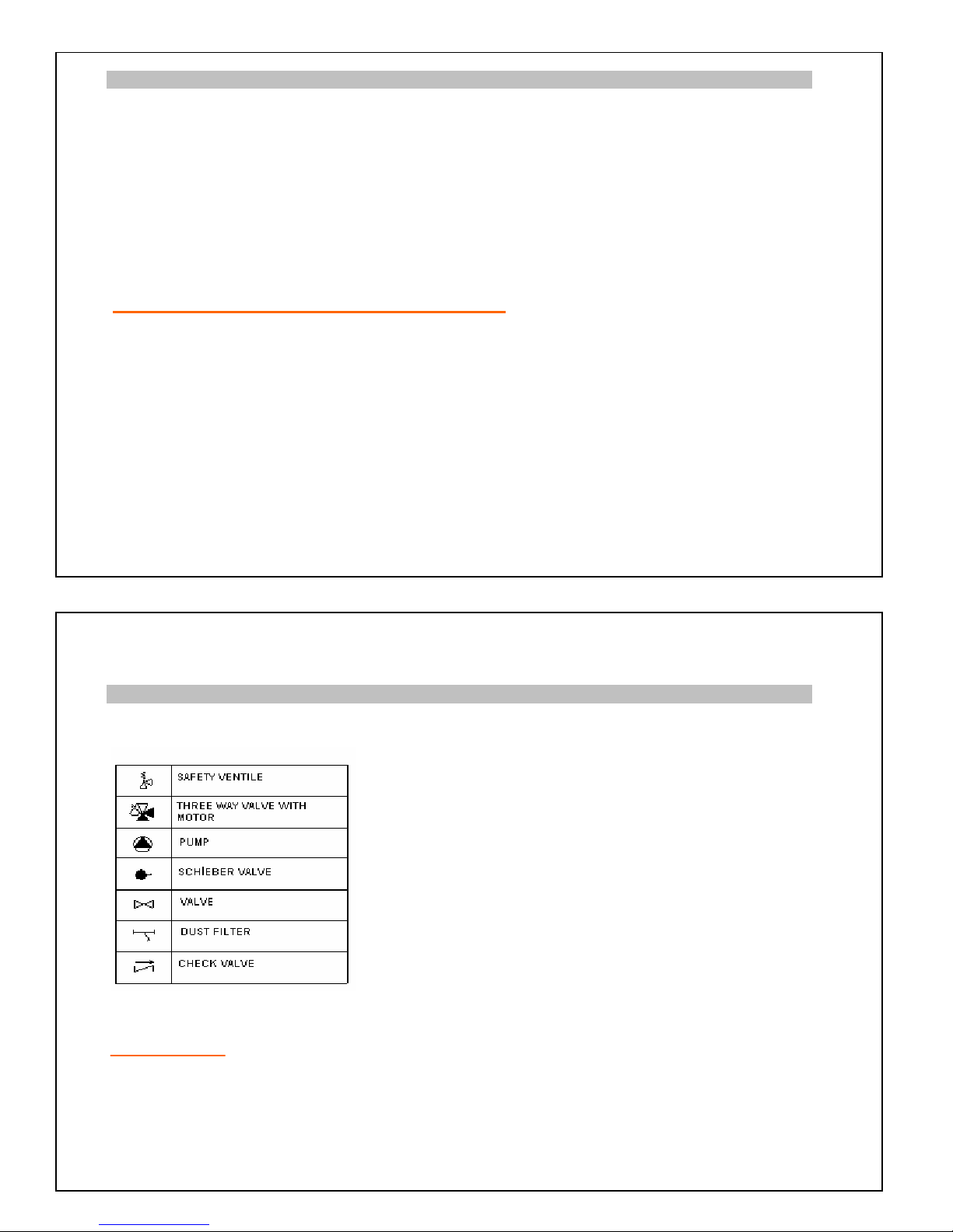
THE MEANING OF THE SYMBOLS USED IN THE DIAGRAM
NOT :
It is better to choose the check valves and valves in pipe dimension rather than pump dimension.
Filter's dimension must be chosen 1 level bi
gg
er that the pipes dimension and must be connected
in horizontal wa
y
. The output of safety ventiles must be connected to water collecting path with a
pip
e. In the systems which thermostatic valve is used, in wet places normal radiator valve must be
used.
Page 10
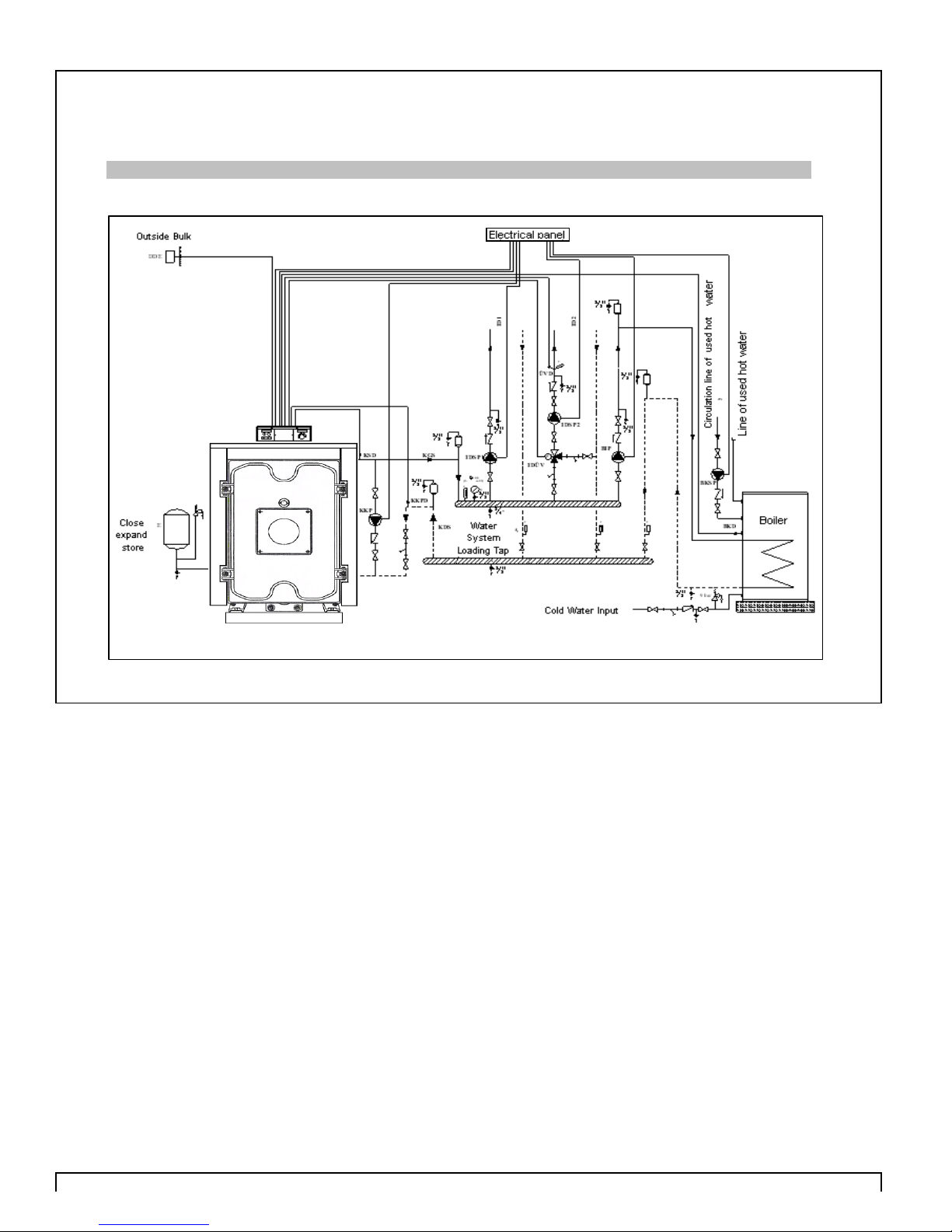
DIAGRAM OF A SAMPLE SINGLE BOILER HEATING CIRCUIT WITH WATER HEATER
OM SERIES CAST IRON BOILER
Page 11
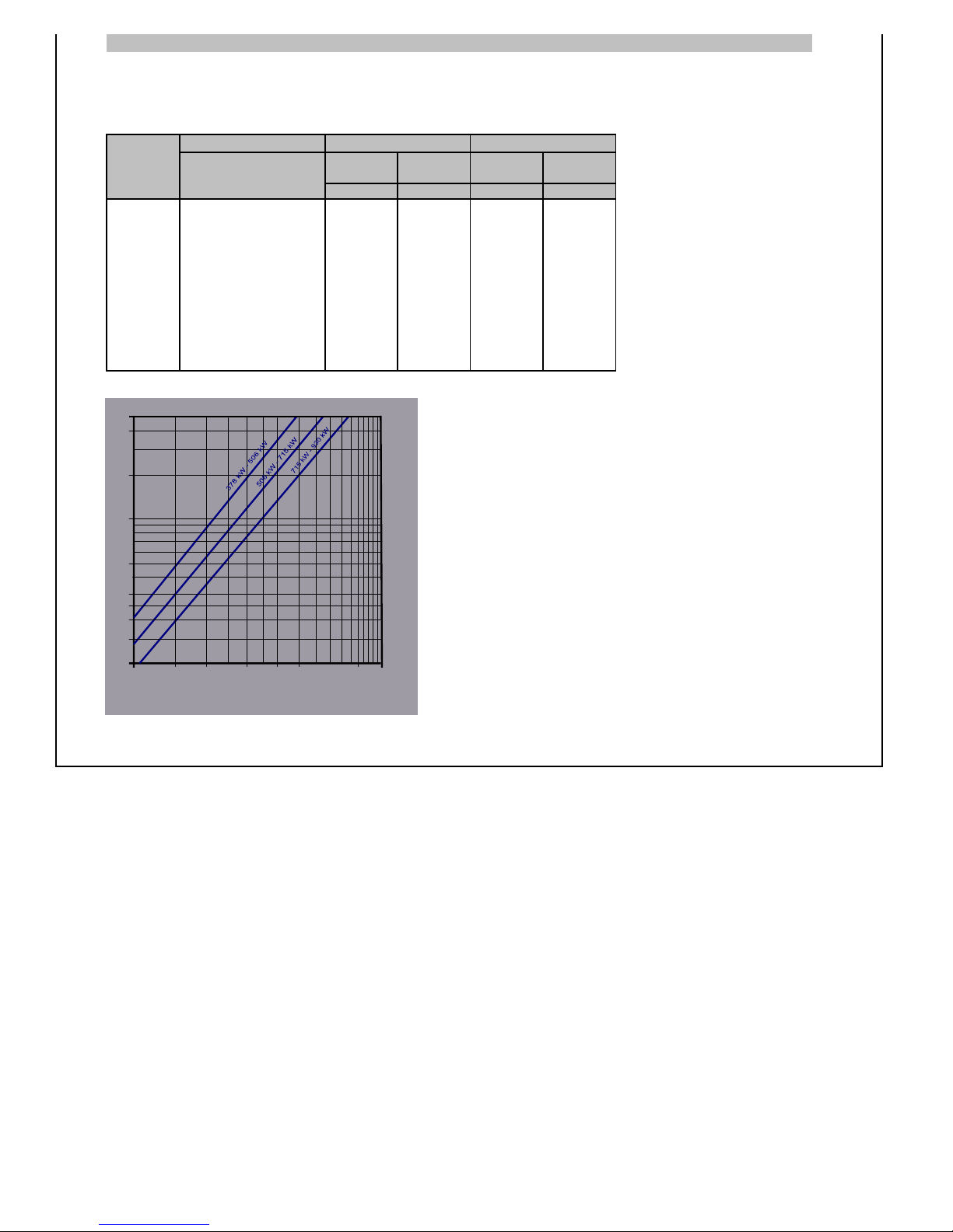
WATER CIRCULATION PRINCIPAL
For healthy working conditions of the boiler,temperature difference between water forward and water
return must not be more than 20 °C
And boiler must not be started or work under the water volumes which is mentioned in the above table.
Boiler Capacity
Type kCal/h kW Water Water Part Water Water Part
Volume Resistance Volume resistance
m³/h mbar m³/h mbar
OM 06 325.000 377,9 21,67 102 16,25 54
OM 07 385.000 447,7 25,67 147 19,25 80
OM 08 435.000 505,8 29,00 180 21,75 105
OM 09 485.000 564,0 32,33 160 24,25 78
OM 10 525.000 610,5 35,00 175 26,25 88
OM 11 570.000 662,8 38,00 200 28,50 115
OM 12 615.000 715,1 41,00 220 30,75 130
OM 13 665.000 773,3 44,33 160 33,25 85
OM 14 715.000 831,4 47,67 180 35,75 90
OM 15 755.000 877,9 50,33 205 37,75 125
OM 16 800.000 930,2 53,33 220 40,00 140
t = 15 K
t = 20 K
17
10
100
500
400
200
100
50
30
10
20
15
25
302015 40
150
Page 12
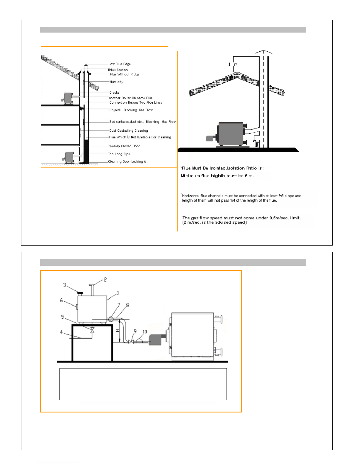
INSTRUCTIONS ABOUT FLUE
Situations Can Make Problems In Flue:
INSTRUCTIONS FOR CONNECTING THE FUEL TANK
The platform of the fuel tank must be strong to carry the tank. If the fuel tank is outside tank and
connection pipes must be isolated. Fuel tank must be positioned in higher level than the burner.
the hei
g
ht difference between the burner and fuel tank ( H ) must be more than 4 m. In the season
s
that the boiler is not used,fuel tank must be empty for avoiding corrosion.
1. Fuel Tank 6.Level Sign
2. Air Pipe 7. Heater
3. Filling Pipe 8. Fuel Suction Pipe
4. Unloading Valve Pipe 9. Off Valve
5. Unloading Valve 10. Heater Filter
Page 13
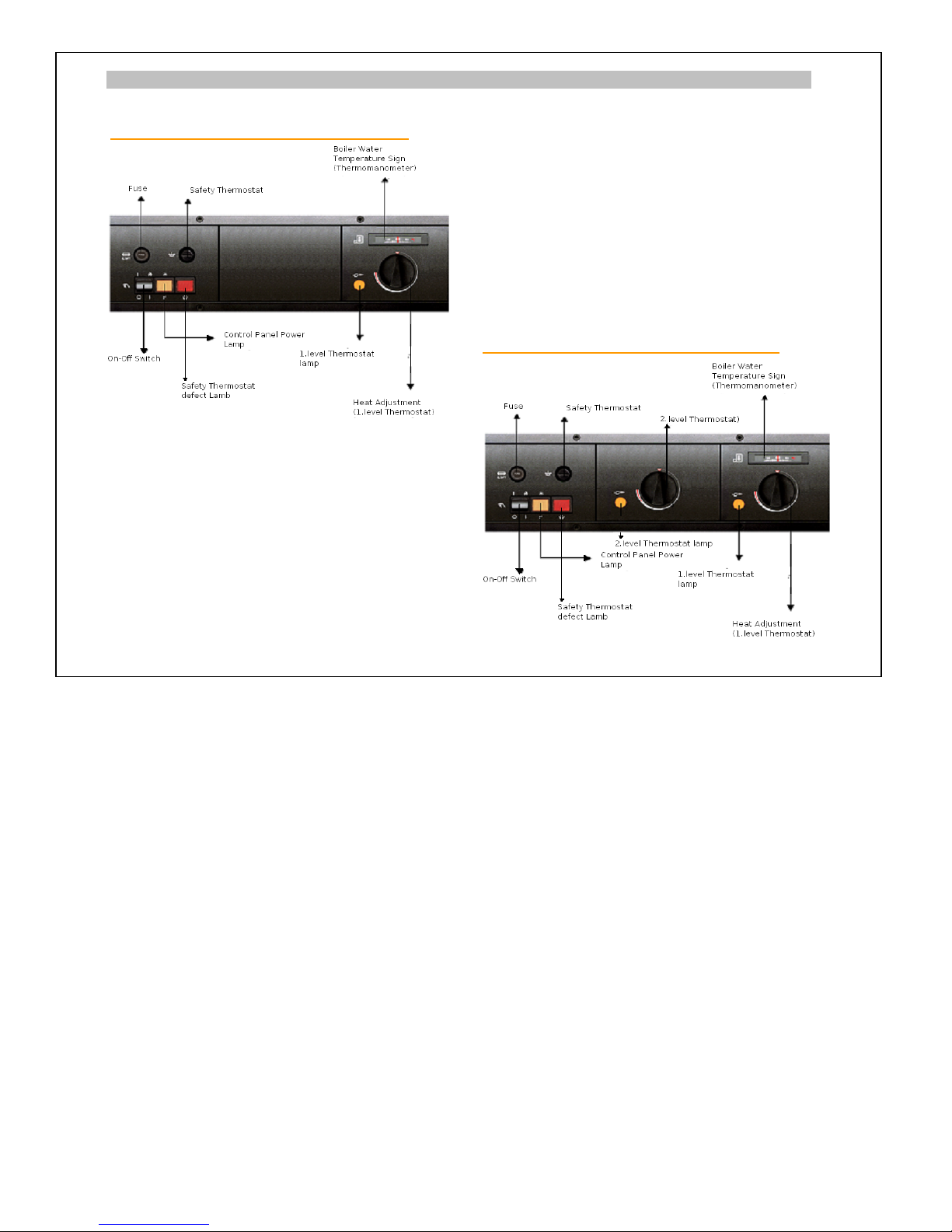
BOILER CONTROL PANELS
Standard Boiler Control Panel
Single Level
Standard Boiler Control Panel
Dual Level
Page 14
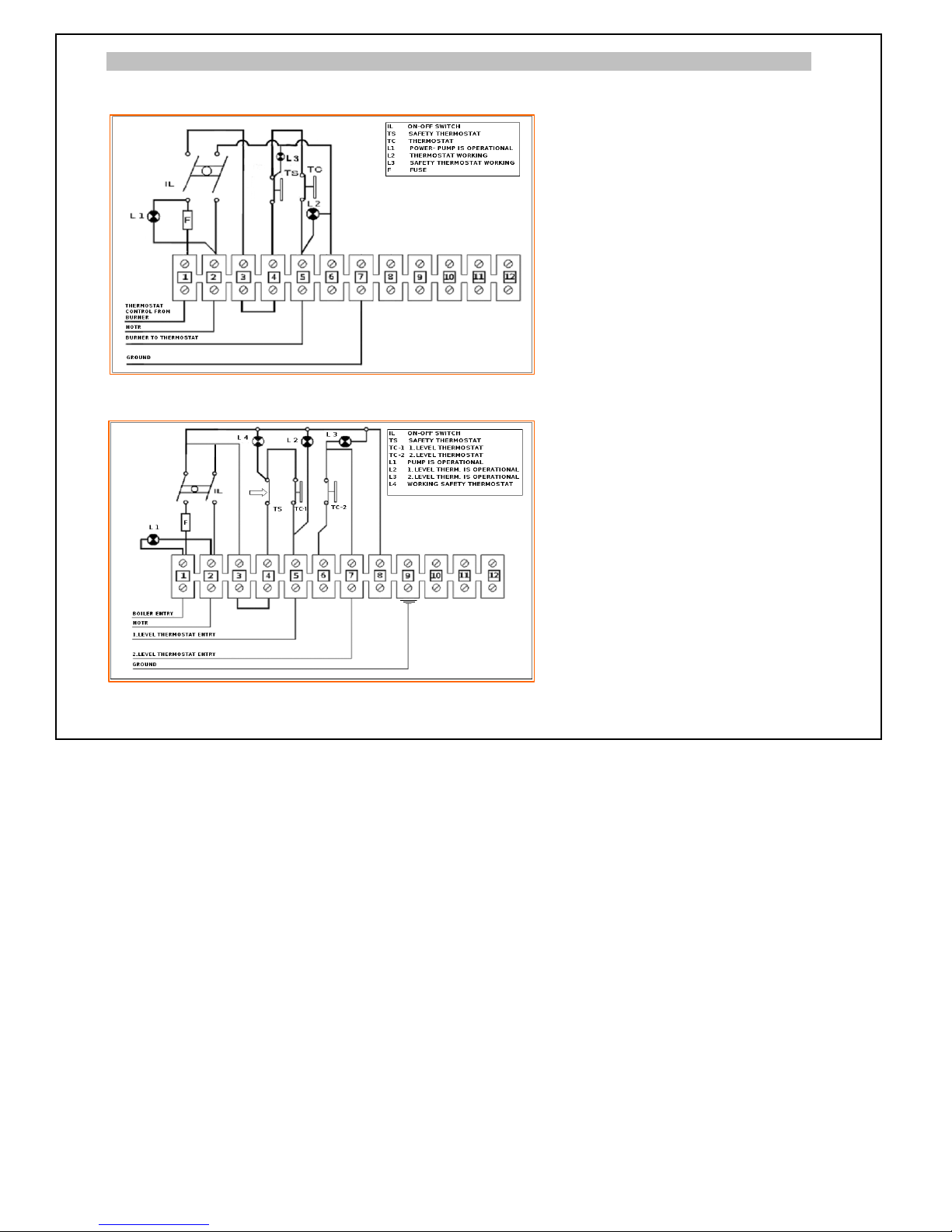
ELECTRICAL DIAGRAMS
Standard Boiler Control Panel (Single Level) - Electric Diagram
Electric feedings is 220 V 50 Hz. Monophase
Standard Boiler Control Panel (Dual Level) - Electric Diagram
Electric feedings is 220 V 50 Hz. Monophase
21
Page 15
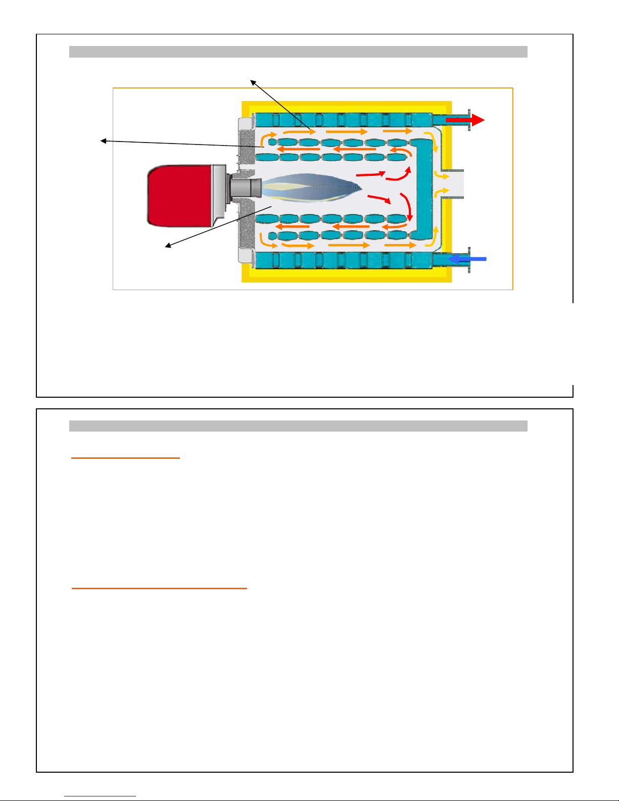
CAST IRON SECTIONS WITH HIGH EFFICIENCY 3 DRAUGHT DESIGN
3rd Pass
( Smoke Channels)
2nd Pass
3 draught design forces the flue gas to circulate inside the body of the boiler three times before the
chimney exit, transfering all usefull energy to the water inside the sections. The optimized combustion
chamber combined with perfect heat insulation provides maximum fuel efficiency.
The combustion room of the boiler is positive pressure. Boiler is working under horizontal 3 pass
principal.
OPERATING INSTRUCTIONS
Heating System
In the system the difference between direct flow temperature and the return temperature of the water
must not be over 20 °C. The return water temperature must be over 50-55 °C. Boiler protection pump
must be used for increasing the return water temperature. The water level of the system must be measured every day (if it is open system by hidrometer,if it is closed system by manometer) and water must be
added if the level is measured low. But this water addition must not be made while the s
y
stem is hot. If
there are problems that cause water leakages they must be fixed as soon as possible.
Plumbing system must be made by certificated professionals, under the terms of EN standards. EN
approved materials must be used in the system.
Fuel And Electrical Connections
These connections must be made b
y
certified profesionals under the terms of EN standards.EN approved
materials must be used in the system.
Burner,control panel, ecopanel etc. Manufacturers' or distrubutors warnings, instruction manuals must be
read .
Burner must not be started before boiler circulation starts.If circulation or protection pump has a failure
burner must be switched off. This system must work coordinarily. Turning the pumps on when the water
heat gets over 40 °C is completely wrong. Circulation pump and burner must work simultaneously.
Protection pump must be chosen properly accoridng to the capacity of the boiler.The connection of the
pump to the collectors must correctly made with valve and thermostat connection. This way,system can
stop in adjusted temperature.In any failure situation(contactor,tehermic failure,electric cut,other failures.)
when the pumps are not working ( heating and protection pumps etc..) burner must not start. Must be
switched off.System must do this automatically.
Electrical system must be made according to all above information.
1st Pass
Page 16

LOADING AND UNLOADING BOILER WATER
Unloading Water Of The Boiler
Plumbing and all radiator valves must be opened if the boilers water will be unloaded.
All the s
y
stems water can be unloaded by boilers drainage as if the boiler is in the bottom of the system.
If some part of heating system is under the boiler room,unloading the water process can be made at a
point at the bottom of the system.
Loading Water To The Boiler
Water must be loaded from the tap over the plumbing system to the boiler.
During the loading process all valves of the plumbing system and the radiators must be opened.
For preventing air fill to the system this operation must be made slowly and the stopper in the top
must be opened. When water comes from this stopper it means that the process is finished. Air must be
taken from every radiator.
Water must be in
q
uality which mentioned on Page 12,''plumbing instructions''.
Boiler must not be filled up with water when it is hot. This can cause cracks in sections.
INSTRUCTIONS FOR PRODUCT DISPOSAL
Cast iron heating boilers are used for long years according to the specifications of its materials and they
are long term equipments.
Life time period for these equipments which is declared in the legal documents is 15 years .
According to this situation renewing of these items are generally done because of technological reasons.
Cast iron boilers,which are produced with human-kind materials can be disposed of as follows .
Cast Iron Body (Grey Cast Iron ) Through iron scrap dealers and cast iron melting companies
Pi
p
es and Cabin Steels Through iron scrap dealers
Other Metal Parts Through iron scrap dealers
Thermal Ceramic and other Isolation Materials Through common waste system
***For more information please get in contact with licensed services.
24
Page 17
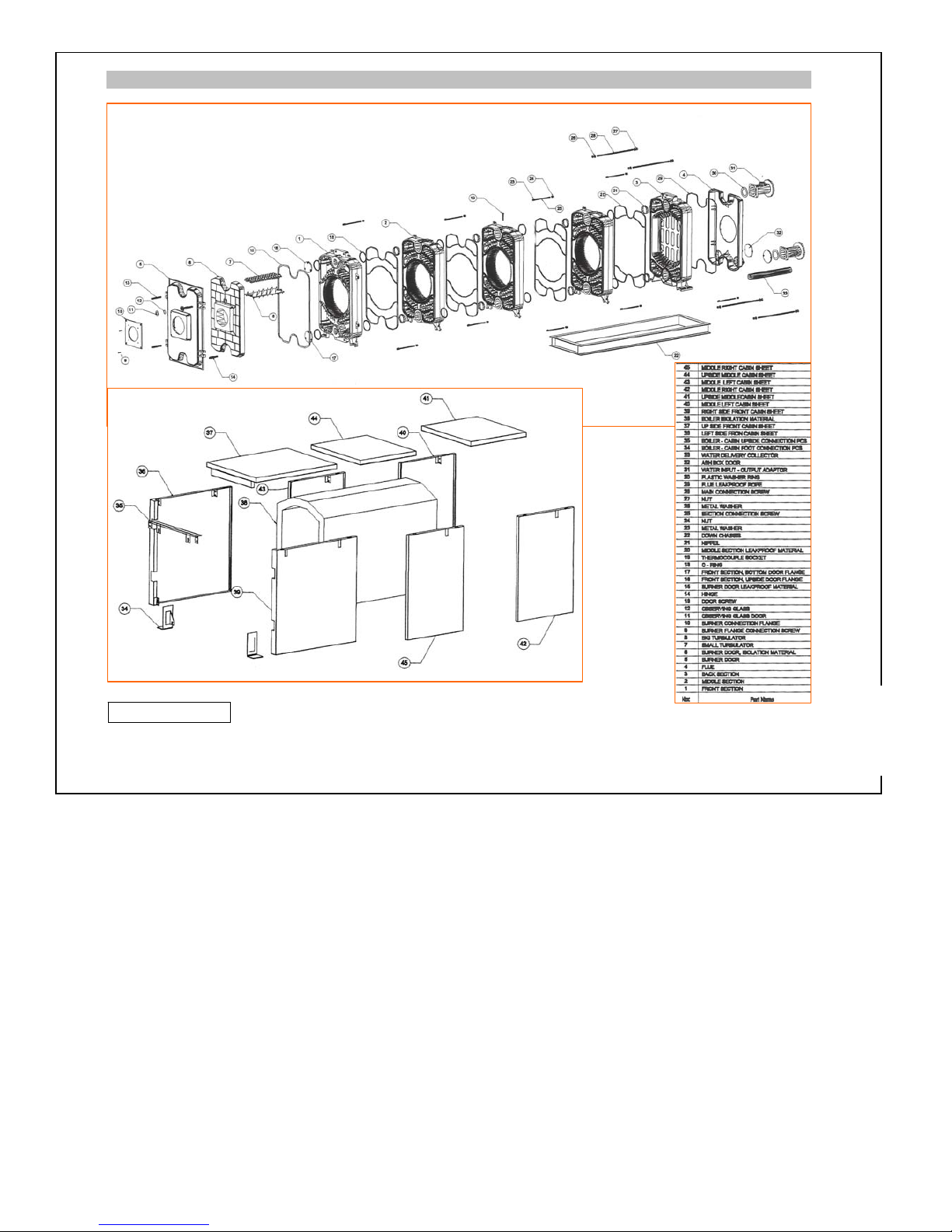
OM SERIE CAST IRON BODY - BOILER CABIN PARTS LIST
*** Safety valve and expansion tank must be connected directly to the boiler and the place of use,without using
any valve between
25
! IMPORTANT
Page 18
0,30
1,20
2,70
3,30
3,90
4,50
2,10
100 200 300 400 500 600 800700
100
130
180
200
220
160
10 20 30 40 50 60 8070 90 100
900
5,10
5,70
Page 19
IMPORTANT INSTRUCTIONS ABOUT BOILER ROOM
! There must not be an
y
other equipments such as aspirator, air condition central etc. in the boiler rooms.
These kind of e
quip
ments can make vacuum effect and defect boilers pull force. This can cause burner
failures.
! The ceilin
g
of the boiler room can be isolated for sound and heat isolation.The position and place of the
boiler is important for sound isolation of the boiler.
! Boiler room must have a
g
ood lighting and control switches of lighting must be outside of the boiler room.
! There must not be e
quip
ments like water pump,contactor etc.. n the boiler room.
! Gas alarm e
quip
ments must be placed to the proper highth as mentioned on standards.
! No one exce
p
t the responsible person should get in to the boiler room.
Children must not enter to the boiler room.A second key must be kept in safe place for urgent matters.
! Fuel tanks must be
p
ut in another place which is rounded by walls.Natural air conditioning is needed for
this place. Boiler room must be air conditioned by natural or other ways.
! Humidit
y
must be prevented in boiler room.
! Boiler room must have the re
q
uested dimensions .
! There must not be an
y
kind of explosive , burning and flameable materials in the boiler room.
! There must not be any kind of explosive , burning and flameable gases in the boiler room atmosphere.
! For the efficienc
y
of the burner and the boiler,boiler room must be kept clean and dry.
! For feedin
g
water to the boiler,water line must be arranged near the boiler.And for filling out the water of
the boiler in necesarry conditions, there must be a connection to drainage in the system.
! If there are an
y
electric keys,cables etcc.Which can cause short circuits must be fixed,renewed as soon a
s
possible.
! In LPG or li
q
uid fuel use;boiler room, flue, system and plumbing issues must be under parameters of EN
standarts and gas offices orders. is not responsible for any failure or problems that will be occured
because of inadequate or not sufficiently qualified conditions of boiler room,plumbing and other systems.
! The instructions of local
g
as delivery must be applied.
! Before
p
ainting keep flameable materials out.
! Before an
y
welding operation in boiler room, boiler must be stopped and the gas flow must be stopped
b
y
turning of the gas valve.
! Do not touch the boiler when it is hot.
! Boiler must not be installed on car
p
et.
Switch off the boiler immediately if there is danger of burning or explosion (elecricity problem,
gas leakage, liquid gas and liquid fuel leakage etc.).
Positioning the Boiler :
boilers must be positioned and placed in the terms of fine protection laws with caution
When installin
g
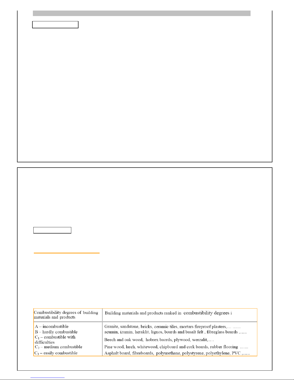
and operating the boilers it is necessary to keep a safe 200 mm distance from combus-
tible materials with combustibilit
y
degrees B,C1,C2
For easily flammable materials with combustibility degree C3 ,which burn quickly and by themselves also
after the ignition source removal the safe distance is doubled it means 400 mm.
The safe distance is to be doubled also in case that the combustibility degree of building material wasn't
p
roved.
28
27
! IMPORTANT
! CAUTION
Page 20
BOILER ROOM AIRING
There are three reasons for fresh air in boiler rooms.
1.The burnin
g
air needed for the burning in the boile
r
2.The air needed for prevention of dirt and dust,for releasing the gases and fuel to put out
3.The air needed for overheatin
g
in the boiler room.
Airin
g
for first two reasons are continously needed.The thirs one is needed
es
p
ecially for the boilers which are working on summer time.
Maximum tem
p
erature for the boiler room must be 32 °C
Boiler room must be
p
rotected against freezing.
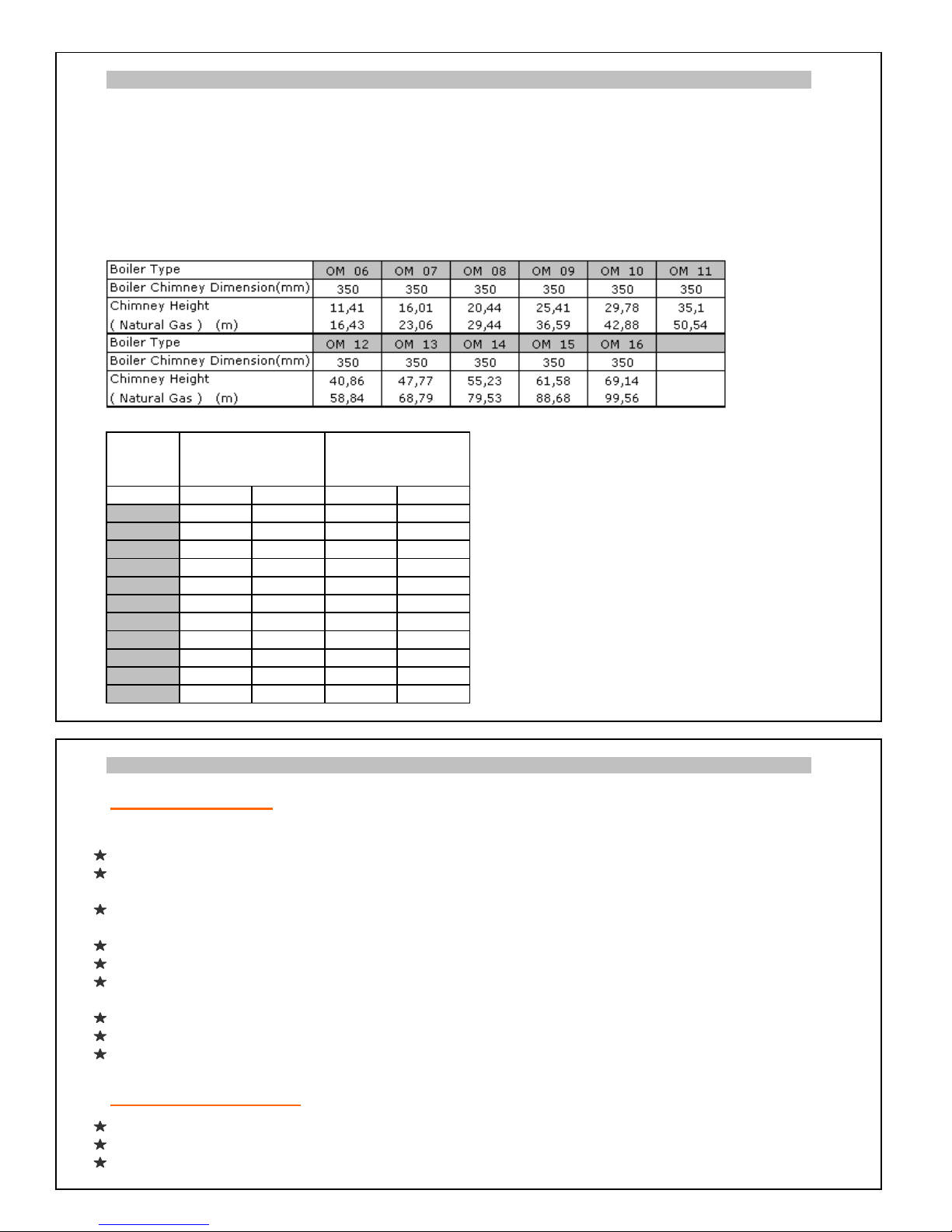
If the fuel is natural gas
Boiler
Type
* If natural airing system is used. ** Ventilating aring
system is used
*** Bottom Up Bottom Up ***Bottom value shows the clean air input up shows the
OM 06 1.971 985 1.224 816 air output.
OM 07 2.285 1.142 1.450 967
OM 08 2.546 1.273 1.639 1.093
OM 09 2.808 1.404 1.827 1.218
OM 10 3.017 1.509 1.978 1.319
OM 11 3.253 1.626 2.147 1.432
OM 12 3.488 1.744 2.317 1.545
OM 13 3.750 1.875 2.505 1.670
OM 14 4.011 2.006 2.694 1.796
OM 15 4.221 2.110 2.844 1.896
OM 16 4.456 2.228 3.014 2.009
CHECKINGS AND STARTING THE BOILER
Pre Controls
Following controls must be done before starting the boiler. If there are any problems or failure, boiler
must not be started.
Water level of the boiler must be controlled. Water must be added to the boiler if the water level is low.
Please call technicians if there is a water leakage. Leakage must be prevented before starting the
boiler. If there is a leaka
g
e in the plumbing system,boiler must be started after repair.
Flue connections must be controlled. Boiler must not be started before re
p
airing the connection if there
is a problem.
Area must be properly air conditioned.
Gas valves must be checked as if they are on if gas fuel is used in the boiler.
Liquid fuel level of the tank must be controlled and fuel valve must be opened if liquid fuel is used in
the boiler. Fuel - burner connection must be controlled.If there are any problems filters must be cleaned.
Working and the directions of the pumps must be controlled.
Electric ssytem of the control panel must be controlled.
All water and gas valves of the boiler must be opened.
All other connections must be controlld according to the system options.
Starting The Boiler
Turn the main electric switch of the boiler room on. Working lamp will be on.
Start the circulation pump
Turn the ''on / off '' switch of the burner to the mode ''on'' (Check the burner instructions manual.)
The indicator light will be on .
**Volume of Air
*Net Cross Section of
Needed for Force Airing
( m³/h )
Open for Natural Airing
( cm² )
Page 21
Adjust the boiler temperature between 30 - 90 °C .If the burner is dual level, adjust the second level
temperature 5- 10°C lower than the first one. This will turn second level light on.
If the burner does not start follow the instructions written on the manual of the burner.If the burner does
not start after applying the written operations in the manual,call the technical service of the burner.
Stopping The Boiler
Turn the ''on / off'' switch of the burner to the '' off '' position.
Turn the ''on / off'' switch of the control panel to the '' off '' position.
Turn of the circulation pump.
Turn of the fuel valves.
Turn off the main fuse switch of the boiler room
FAILURE FIRST CONTROL
When a problem or failure occurs in the boiler or the burner,please make the following first controls
before calling technical services. Don't do anything rahter than mentioned controls. After these controls
call technical services.
If boiler stops working and doesn't start again ; Safety thermostate may have stopped the boiler
because of overheating at boelr water.In this case wait for the boiler to cool down and please make the
following controls.
Check if fuel is coming to the burner or not. If not make fuel to come to the burner.
Check if pump is working or not. If not this could be the reason of overheating.Please get in touch with
pump manufacturer or distrbutor.
Check if the valves are on or off.Open the valves if they are closed.
Please push the safety thermostate switch after the boiler is cold enough.
Burner must start.
If the boiler doesn't start or if the safety thermostat stop the boiler again please call technical
services.
If the burner safet
y
light is on ; Please check the burner instruction manual or get in contact with th
e
burner manufacturer / distrubutor services.
CARE INSTRUCTIONS
Boiler and burner controls are made in three programs.Daily (in everyday use ),periodic and yearly.
Daily Controls
These are the processes that the user must apply every day in season of everyday use. Please read and
apply the instructions and controls mentioned in ''Pre Control'' section of the manual for daily controls.
Periodic Controls
For efficient use, preventing the possible failures and optimum life of the boiler periodic controls are
im
p
ortant.It is recommended that periodical controls for the boiler must be made by once in every three
months.These periodical controls are made by technicians by applying following processes.
Boilers burning room and smoke channels check and cleaning if needed.
Leakage controls of water input water output of hte boiler and flue connections
Valves check
Pumps check
Fuel filter control and cleaning if needed
Burning control (with eye).Burning and flame adjustments if needed.
Control of the liquid fuel sensor.Cleaning if needed.
Working and safety controls of burner and the boiler.
Yearly Controls
Yearly controls of the boiler must be made by technicians before the season starts. Flue and flue
lines must be cleaned before calling technicians for yearly controls. In yearly controls technicians
apply the following processes.
Page 22
Situation and the leakproof of the sections and rope isolations controls.
Workin
g p
ressure test for burning adjustmenst with the flue gas measurement system if needed.
Sensors and connection of the sensors test.
Boiler burnin
g
room and possible soot layers on smoke channels are checks and cleanings.
Connection and the leak
p
roof of the boilers doors test.
Leak
p
roof of the connections of the boiler test.
Valves tests for
prop
er opening and closing.
Fuel filter test. cleanin
g
if needed.
Sensor of the burner li
q
uids tests.Cleaning or renewing If needed .
Workin
g
and safety controls of burner and the boiler.
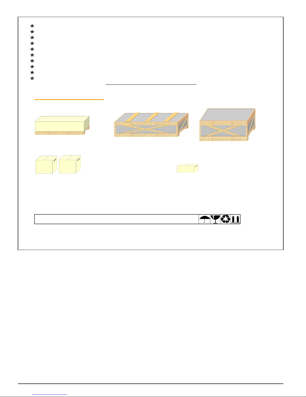
PACKING
Burner Box(pallet and Cardboardbox)
Boiler Cabin Sheet Parts and
insulating jacket Cast Iron Boilers Elements
(wooden box) (80x120 Pallet)
(1 or 2 pallet.According to boiler type)
Mounting Parts box (1 or 2 according to boiler type) Control Panel box
(Nipels,screw,nuts,washer,o-ring,etc.) (Cardboard Box)
(Cardboard Box)
34
Page 23
CLEANING THE BOILER
Before applying mentioned services to the boiler;electric must be cut off from the main switch,fuel valves
must be closed, control panel and the burner must be protected for avoiding any possible damage.
Smoke Channels Cleaning
Because of the soot layer on heating surfaces, 100 °C increase on flue temperature brings out a % 5
decrease on efficiency.
By pulling out the M16 screws and stamps on the 4 hinges which connects door to the front section
,
open the burner door. Clean the burning room, take turbulators out and clean horizontal smoke channels
(2nd and 3rd pass). Than clean the turbulator and put them in to the channels. Close the burner door
strictl
y
.In this cleaning operation soot layer may occur in flue area.This soot particules can be cleaned
by seperating horizontal smoke channels from boiler flue. After this operation these two must be connected again and must be tested for leakage.
The time
p
eriod for cleaning service is variable according to the fuel type of the boiler and period of use.
In boiler cleaning operation ceramic ropes that isolate front door with front section and flue with back
section must be controlled and must be renewed if needed.
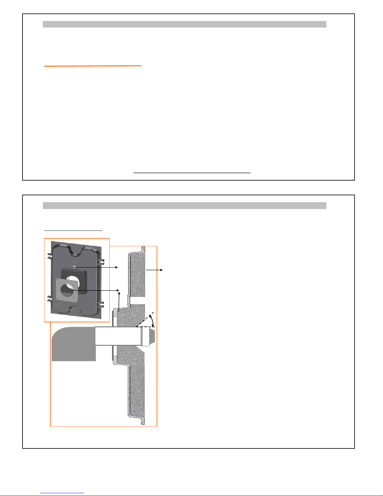
BURNER DOOR AND BURNER CONNECTION
Burner Door In burner connection process there must not be any
empty space left between the front door and the
burner barell.All connection points must be covered
with isolation material for avoiding any air leakage
possibility.
A metal sheet is used for easier assembling of the
burner to the door. This metal sheet is made of 12
mm thickness and in the dimensions of 240x240 mm
(1).
The isolation of the burner door is made of a special
thermal ceramic which is durable up to 1250ºC and
has no defections on human health (2). Please be
sure that this isolation plate is carried carefully and
intensivly during transportation.
There is a ceramic rope fit in to the channels of iso
-
lation door.This prevents leakages between isolation
door and front section of the boiler. After repairing
or cleaning service the doors connection with the
front section must be done properly,strictly.
OM series boilers doors are available for opening to
both sides. This brings advantages of assembling,
reparing and other operations.
A tempered ceramic glass is placed on to the burner
door for watching flame inside (3).
2
1
3
1
45º
Page 24
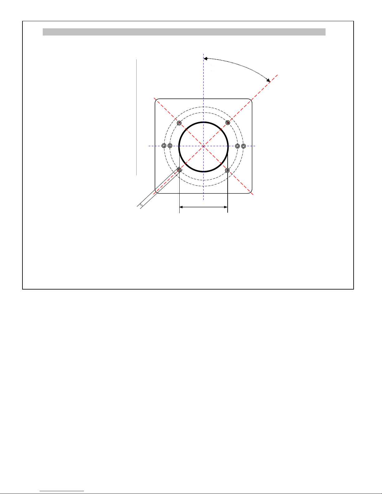
BURNER CONNECTION FLANGE SIZES
Correct,proper burner must
be chosen according to gas
to gas side resistance values of the boiler.
Our company is not
responsible for any possible
problem if not certificated
or out of standard burner
is used with the boiler.
!
37
M 12
225
45º
 Loading...