

HydroTherm KN-6, KN-10, KN-20 Installation & Operating Instructions Manual
KN SERIES GAS BOILER
WITH CONTROL
INSTALLATION & OPERATING
INSTRUCTIONS
IOMKN2-508
MEA #444-05-E MASS Plumbers #G1-06-04-28
DESIGNED AND TESTED ACCORDING TO A.S.M.E. BOILER AND PRESSURE VESSEL
CODE, SECTION IV FOR A MAXIMUM ALLOWABLE WORKING PRESSURE OF 100 PSI,
700 kPa, WATER.
WARNING: If the information in this manual is not followed exactly, a fi re or explosion
may result causing property damage, personal injury or loss of life.
Do not store or use gasoline or other fl ammable vapors and liquids in the vicinity of
this or any other appliance.
WHAT TO DO IF YOU SMELL GAS:
• Do not try to light any appliance.
• Do not touch any electrical switch. Do not use any phone in your building.
• Immediately call your gas supplier from a neighbor’s phone. Follow the gas
supplier’s instructions.
• If you cannot reach your gas supplier, call the fi re department.
Installation and service must be performed by a qualifi ed installer, service agency or
the gas supplier.
CAUTION: Do not use automotive anti-freeze in the boiler waterways. If the use of antifreeze is necessary an
anti-freeze specifi cally formulated for hydronic heating systems must be used or damage to the boiler may
occur voiding the warranty!
INSTALLER, THESE INSTRUCTIONS TO BE AFFIXED ADJACENT TO THE BOILER / WATER HEATER.
CONSUMER, RETAIN THESE INSTRUCTIONS FOR FUTURE REFERENCE PURPOSES.
Advanced Thermal Hydronics
IN UNITED STATES: 260 NORTH ELM ST. • WESTFIELD, MA 01085 • (413) 564-5515 • FAX (413) 568-9613
IN CANADA: 7555 TRANMERE DRIVE • MISSISSAUGA, ONT. L5S 1L4 • (905) 672-2991 • FAX (905) 672-2883
www.hydrothermkn.com

Page 2
KN INSTALLATION AND OPERATION INSTRUCTIONS
AVERTISSMENT. Assurez-vous de bien suivre les instructions données dans cette
notice pour réduire au minimum le risque d’incendie ou d’explosion ou pour éviter
tout dommoge matériel, toute blessure ou la mort
Ne pas entreposer ni utiliser d’essence ou ni d’autres vapeurs ou liquides infl ammables
à proximité de cet appareil ou de tout autre appareil.
QUE FAIRE SI VOUS SENTEZ UNE ODEUR DE GAZ:
• Ne pas tenter d’allumer d’appareil.
• Ne touchez à aucun interrupteur; ne pas vous servir des téléphones se trouvant dans
le bâtiment.
• Appelez immédiatement votre fournisseur de gas depuis un voisin. Suivez les
intructions du fournisseur.
• Si vous ne purvez rejoindre le fournisseur, appelez le service des incendies.
L’installation et l’entretien doivent être assurés par un installateur ou un service
d’entretien qualifi é ou par le fournisseur de gaz.
CONTENTS
Before Your Start ................................................ page 2
Ratings & Capacities ..........................................page 3
Location .............................................................. page 3
Combustion Air & Ventilation ..............................page 3
Venting Guidelines .............................................. page 5
Common Vent Systems ...................................page 13
General Piping Requirements ..........................page 14
Heating System Piping .....................................page 14
Domestic Water Supply Piping .........................page 17
Condensate Piping ...........................................page 18
Gas Supply Piping ............................................page 19
Electrical Wiring ................................................ page 20
Boiler Operation ................................................page 20
Operating Instructions ......................................page 21
Sequence of Operation .....................................page 23
Ignition Troubleshooting ....................................page 24
Checking & Adjustment ....................................page 26
Diagnostics ....................................................... page 27
Maintenance ..................................................... page 28
Troubleshooting ................................................page 29
Repair Parts ......................................................page 30
Wiring ...............................................................page 33
Warranty ...........................................................page 36
BEFORE YOU START
This manual covers the application, installation,
operation and maintenance of a KN series boiler.
To obtain the safe, dependable, effi cient operation and
long life for which this boiler was designed, these
instructions must be read, understood and followed.
The KN boiler series has been design certifi ed by CSA
for use with natural gas under the latest revision of
ANSI-Z21.13/CSA 4.9, Gas-Fired Hot Water Boilers and
CAN1-3.1, Industrial and Commercial Gas Fired
Packaged Boilers. Each unit has been constructed and
hydrostatically tested for a maximum working pressure
of 100 psi, 700 kPa, in accordance with Section IV of the
A.S.M.E. Boiler and Pressure Vessel Code.
All aspects of the boiler installation must conform to the
requirements of the authority having jurisdiction, or, in
the absence of such requirements, to the National Fuel
Gas Code, ANSI Z223.1/NFPA 54-latest revision. Where
required by the authority having jurisdiction, the
installation must conform to the Standard for Controls
and Safety Devices for Automatically Fired Boilers,
ANSI/ASME CSD-1.
If installed in the Commonwealth of Massachusetts, you
MUST FOLLOW the additional instructions contained in
HydroTherm’s instruction sheet MACODE-3. Please
refer to the back of this manual for required regulations.
In Canada, the installation must be in accordance with
the requirements of CSA B149.1 or .2, Installation Code
for Gas Burning Appliances and Equipment.
The owner should maintain a record of all service work
performed with the date and a description of the work
done. Include the name of the service organization for
future reference.
Direct all questions to your HydroTherm distributor or
contact the HydroTherm Customer Service Department
at: 260 North Elm Street, Westfi eld, MA 01085. Always
include the model and serial numbers from the rating
plate of the boiler in question.

KN INSTALLATION AND OPERATION INSTRUCTIONS
Page 3
RATINGS & CAPACITIES
Before installing the KN boiler check the rating plate to
ensure that the unit has been sized properly for the job.
Also ensure that the unit has been set up for the type
of gas available at the installation site. Other important
considerations are the availability of an adequate
electrical supply, fresh air for combustion and a suitable
vent system.
BOILER LOCATION
1. This boiler is suitable for indoor installations only.
Locate the boiler in an area that provides good
access to the unit. Servicing may require the
removal of jacket panels. Allow the minimum
clearances between adjacent construction and the
boiler as listed in Table 1.
NOTE: Service clearances are not mandatory, but
are recommended to ensure ease of service should
it be required.
Table 1 - Clearances
Clearance to Service
Combustibles Clearance
in mm in mm
Top 6 153 24 610
Back 6 153 24 610
Left Side 6 153 6 152
Right Side 6 153 6 152
Front 6 153 36 914
Flue 6 153
5. DO NOT place this boiler in a location that would
restrict the introduction of combustion air into the
unit or subject it to a negative pressure unless the
combustion air is piped from the outside, see the
COMBUSTION AIR & VENTILATION section.
6. NEVER place this boiler in a location that would
subject it to temperatures at or near freezing.
WARNING: Never store combustible materials,
gasoline or any product containing fl ammable
vapors or liquids in the vicinity of the boiler.
Failure to comply with this warning can result
in an explosion or fire causing extensive
property damage, severe personal injury or
death!
COMBUSTION AIR & VENTILATION
WARNING: This boiler must be supplied with
combustion air in accordance with Section 5.3,
Air for Combustion & Ventilation, of the latest
revision of the National Fuel Gas Code, ANSI
Z223.1/NFPA 54 and all applicable local building
codes. Canadian installations must comply with
CSA B149.1 or .2 Installation Code for Gas
Burning Appliances and Equipment, or
applicable provisions of the local building codes.
Failure to provide adequate combustion air for
this boiler/water heater can result in excessive
levels of carbon monoxide which can result in
severe personal injury or death!
2. An optimum site will be level, central to the piping
system, close to a chimney or outside wall and have
adequate fresh air for combustion. Ensure that the
unit is level from front to back and from side to side.
Use metal shims if leveling is required. Electrical and
electronic components must be protected from
exposure to water during operation and maintenance.
DO NOT install this boiler in a location that would
subject any of the gas ignition and other electronic
components to direct contact with water or excessive
moisture during operation or servicing.
3. Ensure that the fl oor is structurally sound and will
support the weight of the boiler.
NOTE: The KN may be installed directly on
combustible fl ooring, but never on carpeting.
4. Locate the boiler in an area that will prevent water
damage to adjacent construction should a leak
occur or during routine maintenance.
To operate properly and safely this boiler requires a
continuous supply of air for combustion. NEVER store
objects on or around the boiler!
CAUTION: Combustion air contaminated with fl uorocarbons or other halogenated compounds such as
cleaning solvents and refrigerants will result in the
formation of acids in the combustion chamber.
These acids will cause premature failure of the
boiler voiding the warranty!
CAUTION: If the boiler is operated while the building
is under construction it must be protected from
wood, concrete, sheet rock and other types of
dust. Failure to properly protect the unit from
construction dust will damage the unit voiding the
warranty!

Page 4
KN INSTALLATION AND OPERATION INSTRUCTIONS
Buildings will require the installation of a fresh air duct
or other means of providing make-up air if the intake
air option isn't used. Any building utilizing other gas
burning appliances, a fi replace, wood stove or any type
of exhaust fan must be checked for adequate
combustion air when all of these devices are in
operation at one time. Sizing of an outside air duct must
be done to meet the requirements of all such devices.
WARNING: Never operate the KN in an environment subjected to a negative pressure unless it
is Direct Vented. Failure to comply with this
warning can result in excessive levels of carbon
monoxide causing severe personal injury or
death!
All Air From Inside The Building
If the boiler is to be located in a confi ned space the
minimum clearances listed in Table 1 must be
maintained between it and any combustible construction.
When installed in a confi ned space without the intake
air option two permanent openings communicating with
an additional room(s) are required. The combined
volume of these spaces must have suffi cient volume to
meet the criteria for an unconfi ned space. The total air
requirements of all gas utilization equipment, fi replaces,
wood stoves or any type of exhaust fan must be
considered when making this determination. Each
opening must have a minimum free area of 1 in2/1000
Btu/hr, 2200 mm2/kW based on the total input rating of
ALL gas utilization equipment in the confi ned area. Each
opening must be no less than 100 in2, 64,516 mm2 in
size. The upper opening must be within 12 in, 300 mm
of, but not less than 3 in, 80 mm from, the top of the
enclosure. The bottom opening must be within 12 in,
300 mm of, but not less than 3 in, 80 mm from, the
bottom of the enclosure.
All Air From Outside The Building
When installed in a confi ned space without the intake
air option two permanent openings communicating
directly with, or by ducts to, the outdoors or spaces that
freely communicate with the outdoors must be present.
The upper opening must be within 12 in, 300 mm of,
but not less than 3 in, 80 mm from, the top of the
enclosure. The bottom opening must be within 12 in,
300 mm of, but not less than 3 in, 80 mm from, the
bottom of the enclosure.
Where directly communicating with the outdoors or
communicating with the outdoors through vertical ducts,
each opening shall have a minimum free area of 1in2/
4000 Btu/hr, 550 mm2/kW of the total input rating of all
of the equipment in the enclosure.
Where communicating with the outdoors through horizontal ducts, each opening shall have a minimum free
area of 1 in
2
/2000 Btu/hr, 1100 mm2/kW of the total
input rating of all of the equipment in the enclosure.
When ducts are used, they must have the same crosssectional area as the free area of the opening to which
they connect.
Table 2 - Make-up Air Duct Sizing
Required Cross Sectional Duct Area
Input 1/4 in, 6.4 mm Metal Wooden
(MBH)
Wire Screen Louvers Louvers
in2 cm2 in2 cm2 in2 cm2
600 150 967 200 1292 600 3869
1000 250 1612 334 2154 1000 6448
2000 500 3224 668 4308 2000 12,896
When calculating the free area necessary to meet the
make-up air requirements of the enclosure,
consideration must be given to the blockage effects of
louvers, grills and screens.
Screens must have a minimum mesh size of 1/4 in,
6.4 mm. If the free area through a louver or grill is not
known ducts should be sized per Table 2 above.
Direct Intake Air Option - General
This confi guration provides combustion air directly to the
boiler’s air intake using a dedicated pipe when using the
direct vent option. Combustion air can be drawn in
horizontally through an outside wall or vertically through
the roof, see Figures 1, 2, 3 & 4. It must be sized per
Table 3.
Single wall galvanized smoke pipe, single wall aluminum
pipe, fl exible aluminum pipe, PVC or CPVC pipe can be
used for the intake air pipe.
Table 3 - Intake Air Pipe Sizing
Model Pipe Diameter
Size in2 mm2
600 5 127
1000 6 152
2000 9 229
NOTE: All joints in metal intake air systems must be
secured using corrosion resistant fasteners and
sealed using a suitable Silicone caulk. If PVC or
CPVC is used, the joints must be cleaned with a
suitable solvent and connected using a solvent
based PVC cement. The intake air system MUST be
supported by the building structure not the boiler.

KN INSTALLATION AND OPERATION INSTRUCTIONS
Page 5
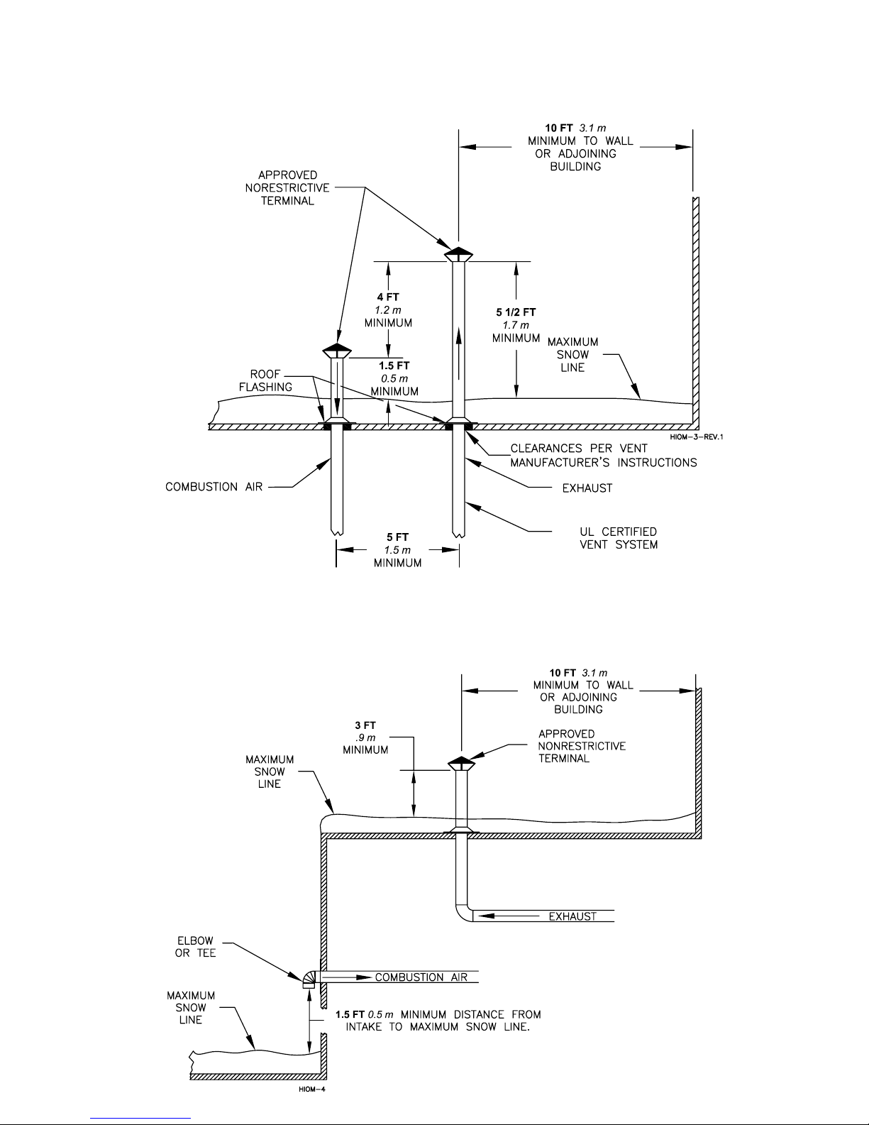
Direct Intake Air Option - Vertical
The maximum equivalent length for the vertical intake
air pipe is 80 ft, 19.7 m. Each 90° mitered elbow and
the intake air cap are equal to 10 ft, 3.3 m of straight
pipe. If 90° long sweep elbows are installed use the
manufacturers recommended equivalent length.
A listed, nonrestrictive intake air cap must be used. The
intake air cap must terminate as shown in Figure 3. The
penetration point in the roof must be properly fl ashed
and sealed. Approved caps are listed in Table 4.
Direct Intake Air Option - Horizontal
The maximum equivalent length for the horizontal intake
air pipe is 80 ft, 19.7 m. Each 90° mitered elbow and
the intake air terminal are equal to 10 ft, 3.3 m of
straight pipe. If 90° long sweep elbows are installed use
the manufacturers recommended equivalent length.
Horizontal runs that exceed 5 ft, 1.5 m must be
supported at 3 ft, 0.98 m intervals with overhead
hangers. The intake air terminal must terminate as
shown in Figures 1, 2 or 4. Approved terminals are listed
in Table 5.
Table 4 - Vertical Intake & Vent System Components
Company Description Part Number Dia., in
Flex-L 5
Flex-L 6
Flex-L 9
Heat Fab Rain Cap 5500CI 5
Heat Fab Rain Cap 5600CI 6
Heat Fab Rain Cap 51000CI 9
Pro Tech Rain Cap FSRC5 5
Pro Tech Rain Cap FSRC6 6
Pro Tech Rain Cap FSRC10 9
Z Flex 5
Z Flex 6
Z Flex 9
Table 5 - Horizontal Intake & Vent System
Components
Company Description Part Number Dia., in
Flex-L Vent Adapter 5
Flex-L Vent Adapter 6
Flex-L Vent Adapter 9
Termination T
Termination T
Termination T
Termination EL
Termination EL
Termination EL
Heat Fab Vent Adapter 9501KN10 5
Heat Fab Vent Adapter 9601KN10 6
Heat Fab Vent Adapter 91001KN10 9
Termination T 9590TEE 5
Termination T 9690TEE 6
Termination T 90990TEE 9
Termination EL 7514TERM 5
Termination EL 9614TERM 6
Termination EL 90914TERM 9
Pro Tech Vent Adapter 5
Pro Tech Vent Adapter FSA-HFAG 6
Pro Tech Vent Adapter 9
Termination T 300313 5
Termination T 300314 6
Termination T 9
Termination EL 5
Termination EL 6
Termination EL 9
Z Flex Vent Adapter 5
Vent Adapter 6
Vent Adapter 9
Termination T 02SVSTTX05 5
Termination T 6
Termination T 9
Termination EL 5
Termination EL 6
Termination EL 9
GENERAL VENTING GUIDELINES
WARNING: The vent installation must be in
accordance with Part 7, Venting of Equipment,
of the National Fuel Gas Code, ANSI Z223.1/NFPA
54-latest revision or applicable provisions of
the local building codes. Canadian installations
must comply with CSA B149.1 or .2 Installation
Code. Improper venting can result in excessive
levels of carbon monoxide which can result in
severe personal injury or death!
All vent systems must be fully supported by the building
structure and not by the boiler. Appropriate thimbles and
fi re-stops must be used where required.
WARNING: Common positive pressure vent
systems are not to be used! Improper installation
can result in excessive levels of carbon
monoxide which can cause severe personal
injury or death!
NOTE: A single acting barometric damper must be
installed in the vent connector if a vertical vent
system produces a negative draft in excess of 0.2 in,
5.08 mm W.C at the fl ue outlet.
NOTE: One of the vent system adapters listed in
Table 5 must be attached to the fl ue outlet of the
boiler before the vent system is connected.

Page 6
KN INSTALLATION AND OPERATION INSTRUCTIONS
VENT SYSTEM OPTIONS
The KN may be vented the following ways:
1) Direct Vent - Positive Pressure, Category IV uses
a vent system certifi ed to UL 1738 for installations
in the United States, ULS636 for installations in
Canada. Combustion air is piped from the outdoors
to the blower inlet.
2) Side Wall Vent - Positive Pressure, Category IV
uses a stainless steel vent system certifi ed to UL
1738 for installations in the United States, ULS636
for installations in Canada. Combustion air is
obtained from the space in which the unit is
installed.
3) Vertical Vent - Positive Pressure, Category IV uses
a stainless steel vent system certifi ed to UL 1738
for installations in the United States, ULS636 for
installations in Canada. Combustion air is obtained
from the space in which the unit is installed.
4) Vertical Vent - Negative Pressure, Category II uses
an approved metal chimney system. Combustion air
is obtained from the space in which the unit is
installed.
DIRECT VENT
POSITIVE PRESSURE, CATEGORY IV
In this confi guration the boiler blower is used to push
the flue products to the outdoors while drawing
combustion air from the outdoors. The INTAKE AIR
OPTION instructions under the COMBUSTION AIR &
VENTILATION SECTION must be followed! The vent
system must be sized per Table 6.
Table 6 - Direct Vent Pipe Size, Positive Pressure
Model Pipe Diameter
Size in
600 5 127
1000 6 152
2000 9 229
Horizontal Direct Vent Systems - Figures 1 & 2
The vent materials used in positive pressure vent systems
must be certifi ed to UL 1738 for installations in the United
States, ULC S636 for installations in Canada. The vent
terminals listed in Table 5 must also be used. Below is a
list of some of the manufactures that have systems that
meet these requirements. Others manufacturers that
have UL certifi ed systems may be used.
2
mm2
Heat-Fab, Inc.
38 Hayward Street
Greenfi eld, MA 01301, (800) 772-0739.
Z-Flex U.S., Inc.
20 Commerce Park
North, Bedford, NH 03110-6911, (800) 654-5600.
Protech Systems Inc.
26 Gansevoort Street
Albany, NY 12202 (518) 463-7284
The maximum equivalent length for the horizontal vent
pipe is 80 ft, 19.7 m. Each 90° elbow and the vent
terminal are equal to 10 ft, 3.3 m of straight pipe. To
maximize the performance of single wall sheet metal
vent systems locate 90° elbows as far from the boiler
as possible and from one another. For best results,
horizontal vent systems should be as short and straight
as possible.
The vent system must be both gas and water tight.
All seams and joints in metal pipes must be joined and
sealed in accordance with the vent system manufacturer’s
instructions.
When horizontal vent runs exceed 5 ft, 1.5m they must
be supported at 3 ft, 0.98 m intervals with overhead
hangers. The vent system must be pitched down, toward
the vent terminal, 1/4 in/ft, 21mm/m. If any part of a
single wall metal vent system passes through an
unheated space it must be insulated with insulation
rated for 400°F, 212°C.
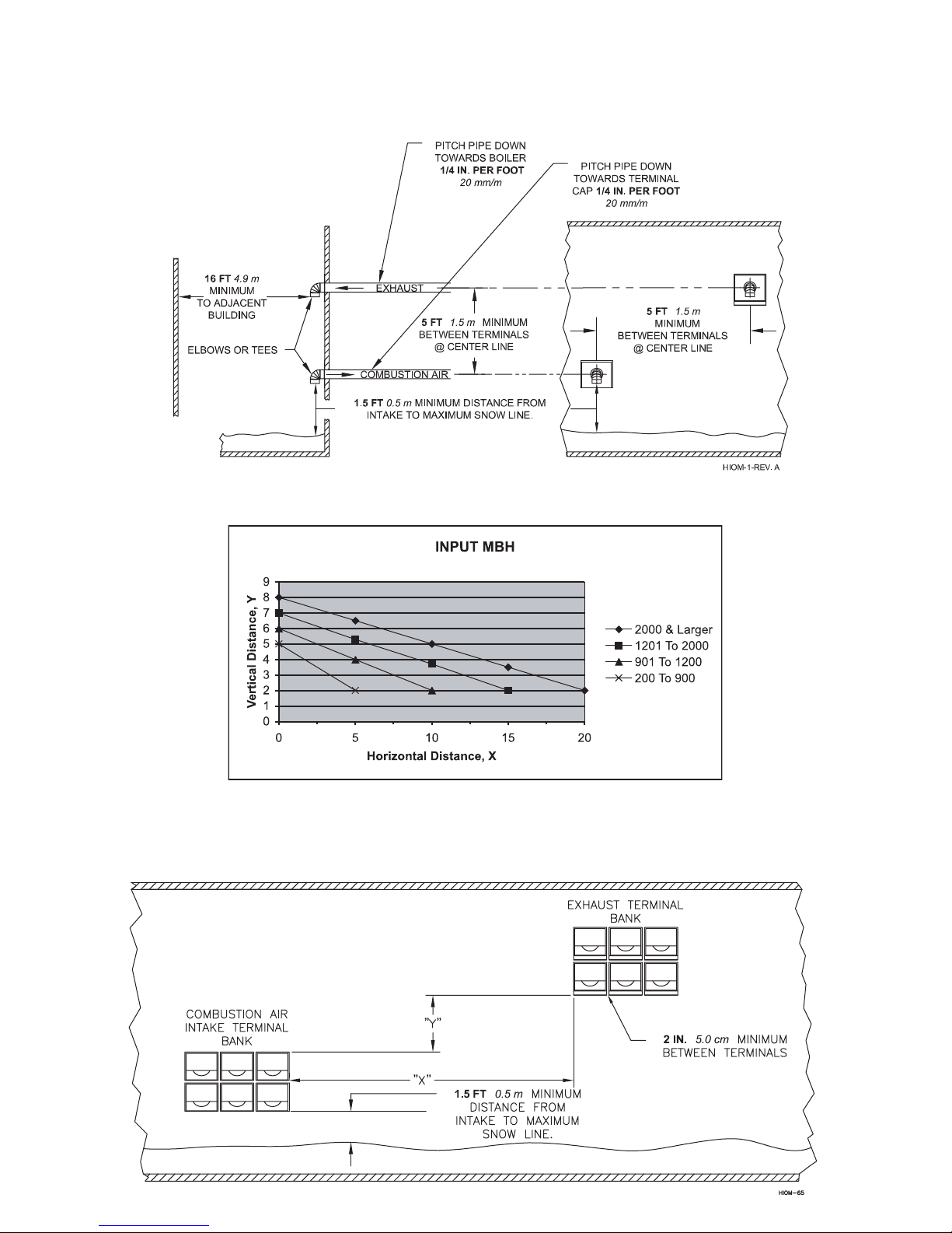
Horizontal vent systems shall terminate at least 4 ft,
1.3 m below, 4 ft, 1.3 m horizontally from or 1 ft,
0.23 m above any door, window or gravity air inlet into
any building. It must not terminate less than 4 ft, 1.3 m
horizontally from, and in no case above or below, unless
a 4 ft, 1.3 m horizontal distance is maintained, from
electric meters, gas meters, regulators and relief
equipment and not less than 7 ft, 2.3 m above adjacent
public walkway. The bottom of the vent terminal(s) shall
be located at least 5 ft, 1.5 m above the air intake
terminal(s) unless there is a 5 ft, 1.5 m distance between
them.
Avoid terminal locations likely to be affected by winds,
snowdrifts, people and pets. Protect building materials
and vegetation from degradation caused by the fl ue
gases.
KN INSTALLATION AND OPERATION INSTRUCTIONS
Page 7
When running horizontal combustion air and venting for
single or multiple units, exhaust and combustion air
terminals must be installed on the same plane (outside
wall) in order to prevent pressure differences due to
prevailing winds. In cold climates, double-wall or insulated
inlet pipe recommended to prevent condensation.
Vertical Direct Vent Systems - see Figure 3
The vent materials used in positive pressure vent
systems must be certifi ed to UL 1738 for installations in
the United States, ULC S636 for installations in Canada.
The vent terminals listed in Table 4 must also be used.
Below is a list of some of the manufactures that have
systems that meet these requirements. Others manufacturers that have UL certifi ed systems may be used.
Heat-Fab, Inc.
38 Hayward Street
Greenfi eld, MA 01301, (800) 772-0739.
Z-Flex U.S., Inc.
20 Commerce Park
North, Bedford, NH 03110-6911, (800) 654-5600.
Protech Systems Inc.
26 Gansevoort Street
Albany, NY 12202 (518) 463-7284
The maximum equivalent length for the vertical vent pipe
is 80 ft, 19.7 m. Each 90° elbow and the intake air cap
are equal to 10 ft, 3.3 m of straight pipe. If any part of
a single wall metal vent system passes through an
unheated space it must be insulated with insulation
rated for 400°F, 204°C. Structural penetrations must be
made using approved fi re-stops.
The top of a vertical vent system must extend at least
1
5
/2 ft, 1.8 m above the roof surface that it passes
through, 4 ft, 1.3 m above the intake air cap, see Figure
3. In addition the vent system must conform to the
dimensions shown in Figure 3. The penetration point in
the roof must be properly fl ashed and sealed.
The vent system must be gas tight. All seams and joints
in metal pipes must be joined and sealed in accordance
with the vent system manufacturer's instructions.
Combination Direct Vent Systems - see Figure 4
The boiler can be vented vertically with the intake air
piped horizontally through an outside wall. Follow the
instructions in the INTAKE AIR OPTION - HORIZONTAL
GUIDELINES on page 4. Also follow the general
instructions in the COMBUSTION AIR & VENTILATION
and GENERAL VENTING GUIDELINES sections.
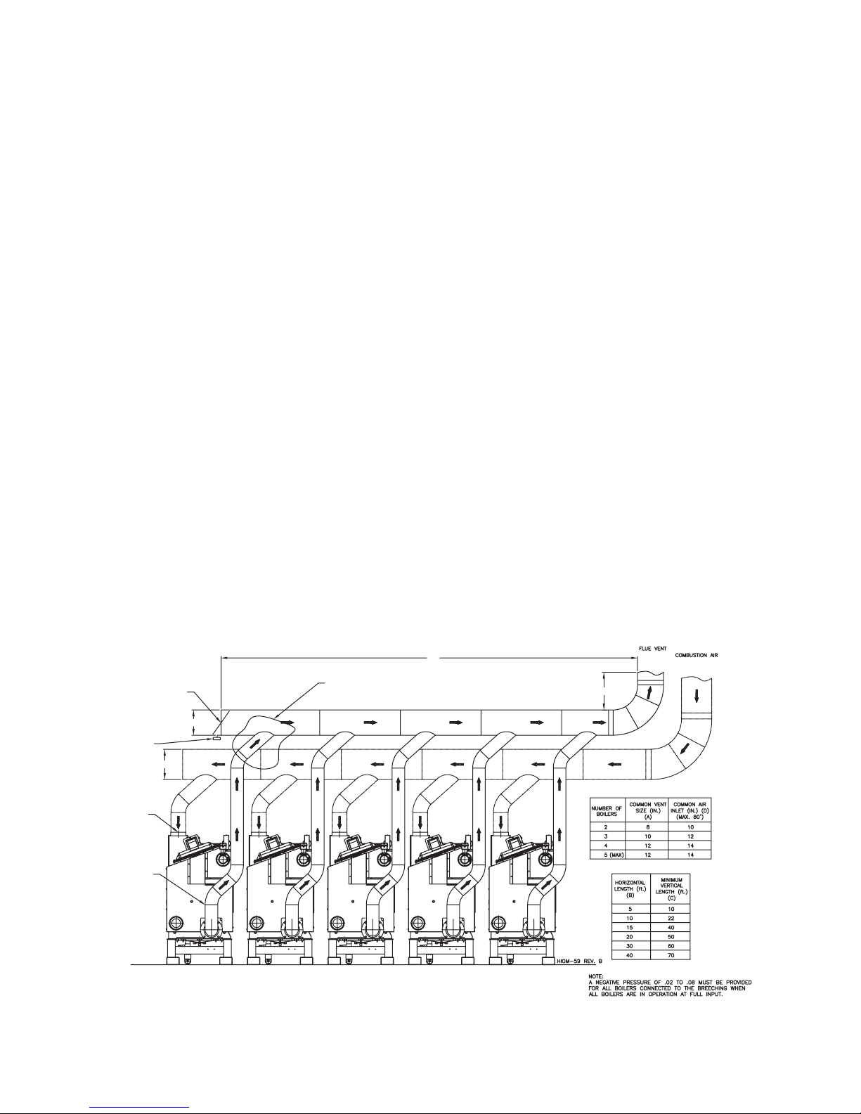
KN-6 Multiple Boiler Venting Category II Venting (Negative)
"B"
ALL CONNECTIONS
DOUBLE ACTING
BARAMETRIC DAMPER
THERMAL SPILL
SWITCH
5" AIR
INLET
5" FLUE
OUTLET
"D"
"A"
BOILER #5
(IF REQUIRED)
BOILER #4
(IF REQUIRED)
TO BE "T-WYE"
BOILER #3
(IF REQUIRED)
BOILER #2
BOILER #1
(ALWAYS LEAD)
"C"
Table 1 - Common Vent Sizes
Table 2 - Vent Lengths
Page 8
KN INSTALLATION AND OPERATION INSTRUCTIONS
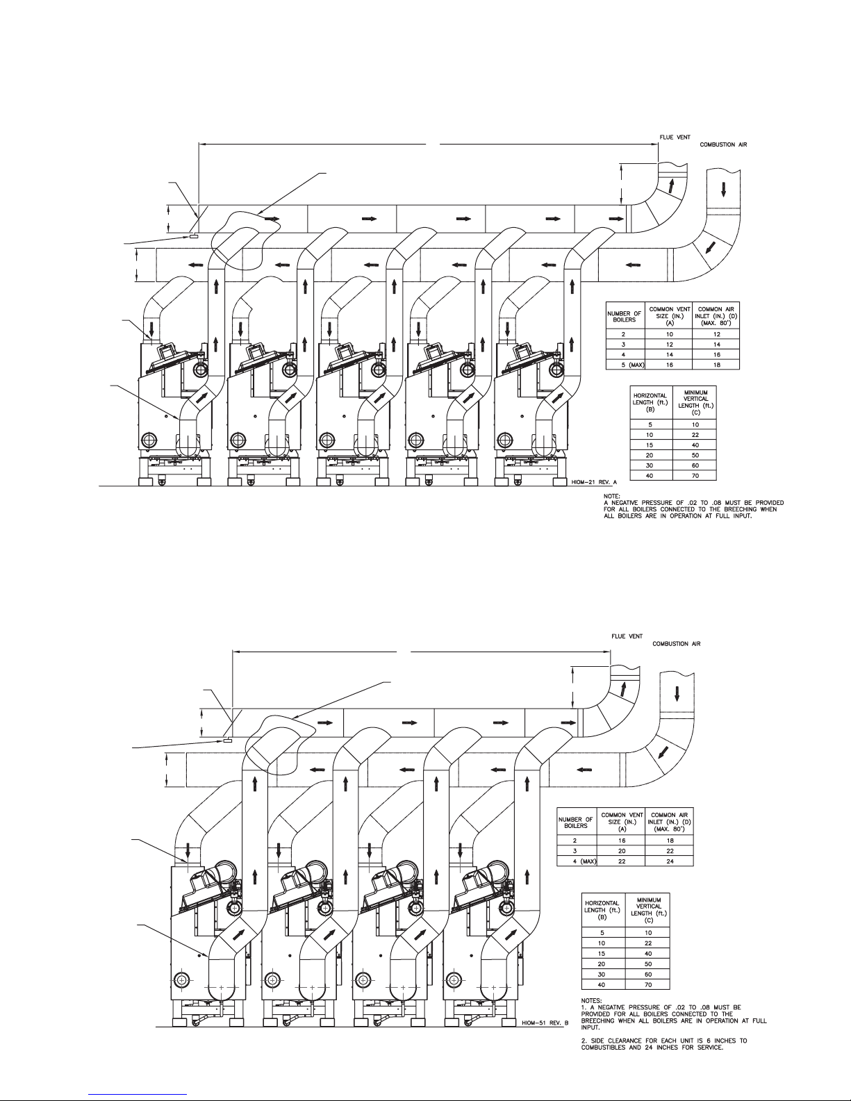
KN-10 Multiple Boiler Venting Category II Venting (Negative)
ALL CONNECTIONS
DOUBLE ACTING
BARAMETRIC DAMPER
THERMAL SPILL
SWITCH
6" AIR
INLET
"A"
"D"
TO BE "T-WYE"
"B"
"C"
Table 1 - Common Vent Sizes
6" FLUE
OUTLET
BOILER #5
(IF REQUIRED)
BOILER #4
(IF REQUIRED)
BOILER #3
(IF REQUIRED)
BOILER #2
KN-20 Multiple Boiler Venting Category II Venting (Negative)
"B"
ALL CONNECTIONS
TO BE "T-WYE"
THERMAL SPILL
SWITCH
DOUBLE ACTING
BARAMETRIC DAMPER
"D"
"A"
BOILER #1
(ALWAYS LEAD)
Table 2 - Vent Lengths
"C"
9" AIR
INLET
9" FLUE
OUTLET
BOILER #4
(IF REQUIRED)
(IF REQUIRED)
Table 1 - Common Vent Sizes
Table 2 - Vent Lengths
BOILER #2BOILER #3
BOILER #1
(ALWAYS LEAD)
KN INSTALLATION AND OPERATION INSTRUCTIONS
Figure 1 - Horizontal Air Intake and Venting for a Single Direct Vent System
Page 9
Figure 2 - Horizontal Air Intake and Venting for Multiple Direct Vent Systems
Page 10
KN INSTALLATION AND OPERATION INSTRUCTIONS
Figure 3 - Vertical Air Intake and Venting for Direct Vent System
Figure 4 - Combination Direct Vent Systems
KN INSTALLATION AND OPERATION INSTRUCTIONS
Page 11
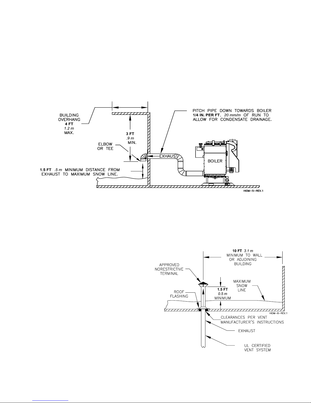
SIDE WALL VENT
POSITIVE PRESSURE, CATEGORY IV
In this confi guration the boiler blower is used to push the
fl ue products horizontally to the outdoors, see Figure 5.
Figure 5 - Side Wall Venting
The air for combustion is taken from the space in which
the unit is installed. The applicable instructions under
the COMBUSTION AIR & VENTILATION SECTION
must be followed! The vent guidelines under the
HORIZONTAL DIRECT VENT SYSTEMS section must
also be followed.
VERTICAL VENT
POSITIVE PRESSURE - CATEGORY IV
In this confi guration the boiler blower is used to push
the fl ue products vertically to the outdoors, see Figure
6. The air for combustion is taken from the space in
which the unit is installed. The applicable instructions
under the COMBUSTION AIR & VENTILATION
SECTION must be followed! The vent guidelines under
the VERTICAL DIRECT VENT SYSTEMS section must
also be followed.
Figure 6 - Vertical Positive Pressure Venting
 Loading...