

HydroTherm KN-20 Field Assembly Instructions
Hydrother m
®
-Series
KN
Gas-fired direct vent
Cast iron boilers
Model KN-20 only
Field assembly
instructions
Also read and follow:
KN Series Gas Boiler
Installation & Operating
Instructions and KN
HeatNet Control Manual
is manual is intended only for use by a qualied heating installer/technician. Read and follow this manual, all supplements and re-
lated instructional information provided with the boiler. Install, start and service the boiler only in the sequence and methods given in
thi
s manual and the documents listed above. Failure to do so can result in severe personal injury, death or substantial property damage.
Do not use the boiler during construction. Construction dust and particulate, particularly drywall dust, will cause contamination
the burner, resulting in possible severe personal injury, death or substantial property damage. e boiler can only be operated with a
of
du
st-free air supply. Follow the instruction manual procedures to duct air to the boiler air intake. If the boiler has been contaminated by
op
eration with contaminated air, follow the instruction manual guidelines to clean, repair or replace the boiler if necessary.
P/N 42-9551 Copyright 2011 Mestek, Inc.
KN Series Gas-fired direct vent cast iron boilers – Field assembly instructions
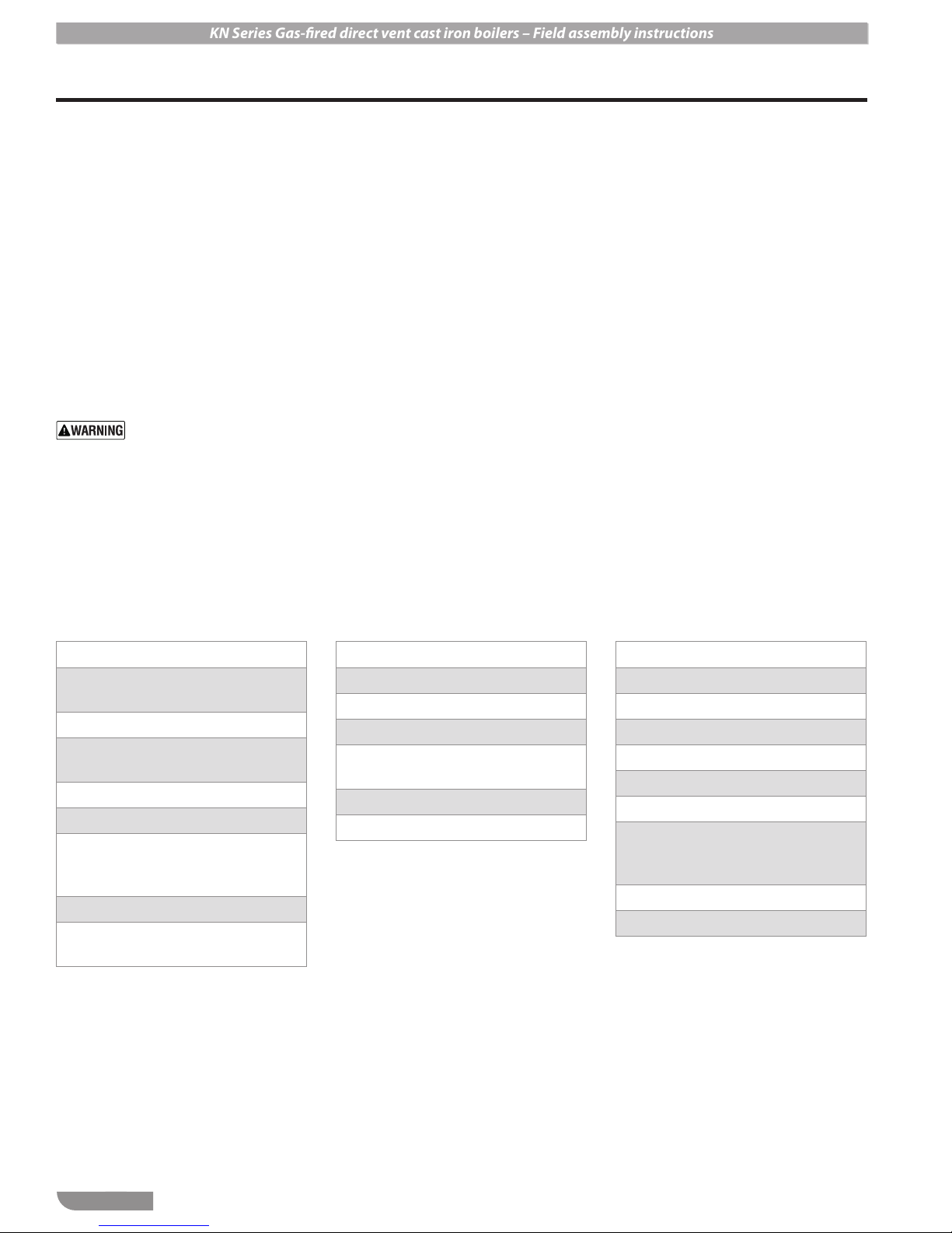
Contents and information
Read before beginning the installation. . . . . . . . 5
Boiler ratings and specifications . . . . . . . . . . . . 6
Installation site preparation . . . . . . . . . . . . . . . 7
Prepare the boiler . . . . . . . . . . . . . . . . . . . . 10
Water piping. . . . . . . . . . . . . . . . . . . . . . . . 11
Gas piping . . . . . . . . . . . . . . . . . . . . . . . . . 18
Wiring a single boiler . . . . . . . . . . . . . . . . . . 20
Control setup . . . . . . . . . . . . . . . . . . . . . . . 25
Vent piping (and air piping when used) . . . . . . 28
Condensate drain line. . . . . . . . . . . . . . . . . . 29
Fill and test the system . . . . . . . . . . . . . . . . . 30
Hazard icons
You will find the following icons
throughout this manual.
(English/French)
The WARNING icon indicates
a hazard that can cause severe
personal injury, death or
substantial property damage.
The CAUTION icon indicates a
hazard that will or can cause minor
personal or property damage.
The NOTICE icon calls out special
instructions that are important, but
are not related to hazards.
Starting the boiler . . . . . . . . . . . . . . . . . . . . 32
Annual start-up . . . . . . . . . . . . . . . . . . . . . . 41
Maintenance . . . . . . . . . . . . . . . . . . . . . . . 42
Replacement parts. . . . . . . . . . . . . . . . . . . . 46
Appendix A — suggested wiring. . . . . . . . . . . 48
Other manuals
You must read and follow this
manual, the KN Series Gas Boiler
Installation and Operating
Instructions, the KN HeatNet
Control manual and all additional
materials supplied with the boiler.
Failure to do so can result in severe
personal injury, death or substantial
property damage.
Boiler/control installation and setup
After completing assembly of the
KN boiler, follow all instructions
in the Installation and Operation
Instructions and Control Manual for
installation, start-up and testing.
2
P/N 42-9551
KN Series Gas-fired direct vent cast iron boilers – Field assembly instructions
Read before proceeding
Customer service and technical support
Direct all questions to your HydroTherm distributor or contact the HydroTherm Customer Service Department at:
260 North Elm Street Westfield, MA 01085.
Always include the model and serial numbers from the rating plate of the boiler in question.
Claims for damage or missing components must be filed immediately against the transportation company by the
consignee.
Codes and standards
Code compliances
All aspects of the boiler installation must conform to the requirements of
the authority having jurisdiction, or, in the absence of such requirements,
to the National Fuel Gas Code, ANSI Z223.1/NFPA 54-latest revision.
Where required by the authority having jurisdiction, the installation must
conform to the Standard for Controls and Safety Devices for Automatically Fired Boilers, ANSI/ASME CSD-1.
In Canada, the installation must be in accordance with the requirements
of CSA B149.1 or .2, Installation Code for Gas Burning Appliances and
Equipment.
Before assembling the boiler . . .
Verify boiler rating and gas supply
• Before assembling and installing the boiler, check the ratings to ensure that the unit has been sized properly for the job.
• Ensure that the boiler will be set up for the type of gas available at the
installation site.
Verify location is suitable
• Ensure the availability of an adequate electrical supply, uncontaminated air for combustion, and that vent (and air) piping can be correctly installed.
• Ensure the boiler can be connected to system water piping and gas
supply.
• e boiler must not be exposed to dripping or spraying water or to
rain.
• If replacing an existing boiler, nd out what caused the boiler to fail
before installing a new boiler. Correct the problems that led to failure,
or the failure may happen to the new boiler.
Attention:
Use of an approved dust respirator is strongly
recommended when handling the insulating components of the boiler
Electrical shock hazard — Disconnect all electrical
power sources to the boiler before making any electrical
connections.
Label all wires prior to disconnection when servicing
controls. Wiring errors can cause improper and dangerous
operation! Verif y proper operation aer servicing.
Failure to comply with the above could result in severe
personal injury, death or substantial property damage.
e electrical connections to this boiler must be made in
accordance with all applicable local codes and the latest
revision of the National Electrical Code, ANSI /NFPA-70.
Installation should also conform to CSA C22.1 Canadian
Electrical Code Part I if installed in Canada. Install a separate 120 volt 15 amp circuit for the boiler. A properly rated
shut-o switch should be located at the boiler. e boiler
must be grounded in accordance with the authority having
jurisdiction, or if none, the latest revision of the National
Electrical Code, ANSI/NFPA-70.
Line voltage eld wiring of any controls or other devices
must use copper conductors with a minimum size of
#14awg. Use appropriate wiring materials for units
installed outdoors.
DO NOT open any gas valve, or aempt to re the boiler,
until all boilers have been set up and veried following the
instructions in the KN Series Gas Boiler Installation &
Operating Instructions.
Failure to comply could cause a boiler failure, leading to
possible severe personal injury, death or substantial property damage.
.
P/N 42-9551
3
KN Series Gas-fired direct vent cast iron boilers – Field assembly instructions
Components and special tools required
Special equipment/materials required for assembly
1. One quart 30-wt motor oil
2. Rubber and leather gloves
3. Rubber or leather mallet
4. Two 2”x4”x12” boards (used for
cushioning when seating push nipples)
5. Two 18-inch pipe wrenches
6. Torque wrench (at least 30 foot-pound
capacity)
7. Deep socket, 11/16” for use with torque
wrench
8. Standard hand tools, wire, nuts, electrical
hand tools
9. 2”x2” steel square stock x 6 inches long,
for driving square-socket pipe plugs
(supplied with boiler in hardware box)
Sealants, lubricants and adhesives supplied with boiler (in hardware box)
Use gloves when working with
these products as specied in
these instructions and in the
product instructions.
1. Silicone RTV-6500 HiTemp: (3) 10oz caulk tubes (for sealing between
sections)
2. Loc-Tite 30557 pipe dope: (1) 16-oz can
(for water and gas piping connections)
3. Hercules Pro Dope: (1) 8-oz jar (for
mixing with 30-wt motor oil, used as
lubricant for push nipples)
4. Res Bond 2300: (1) 11-oz caulk tube (for
sealing burner assembly)
5. Fast-Tack 87: (1) 13-oz spray can (for
securing flue baffles to sections)
Boiler components and shipping information
Skid 1
Cast iron sections (front, rear and
intermediate)
Push nipples
3” x 8” supply nipple and return
nipple
Pipe plugs
Draw rods and hardware
All-thread rods (7/8”) and cast-iron
draw-up plates for assembling boiler
block
Ceramic flue baffles
Hardware box (bolts, nuts, etc., individually packed/labeled by usage)
Base
Burner kit
Ceramic combustion chamber
Drain pan (with inspection cover
plate pre-attached)
Upper casting
4” x 6” boards for section assembly
Skid 2
Jacket components
Jacket insulation
Blower and filter box assembly
Control box assembly
Gas train assembly
Gas train shroud
Components box (igniter, sight
glass, supply and return sensors,
LWCO assembly, etc.)
Flue adapter assembly
Condensate trap assembly
Skid 3
4
P/N 42-9551
KN Series Gas-fired direct vent cast iron boilers – Field assembly instructions
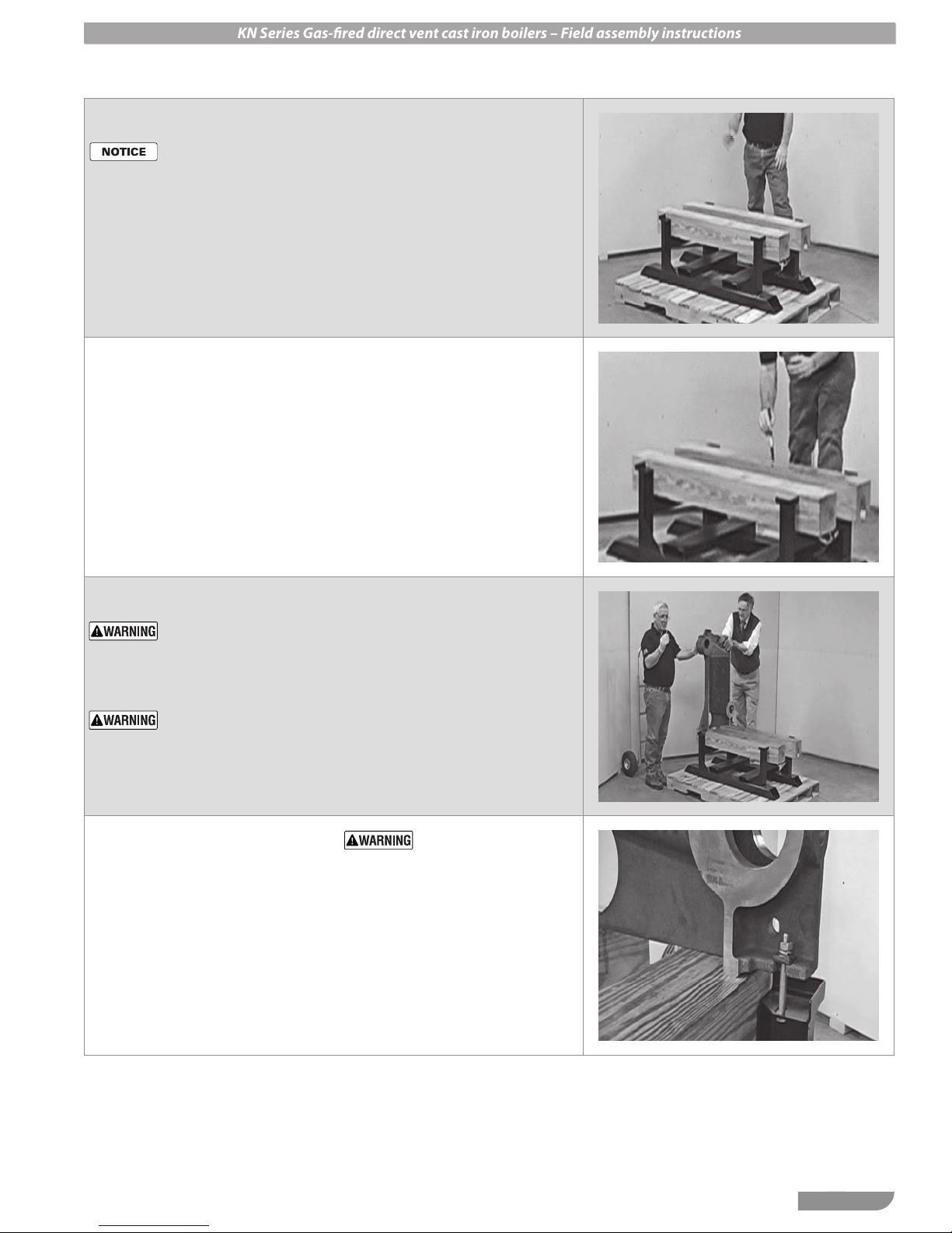
Step 1 Place 4x6 boards on base
Ignore the palee under the
boiler in the manual images
— it is le in place during
assembly for demonstration
purposes only.
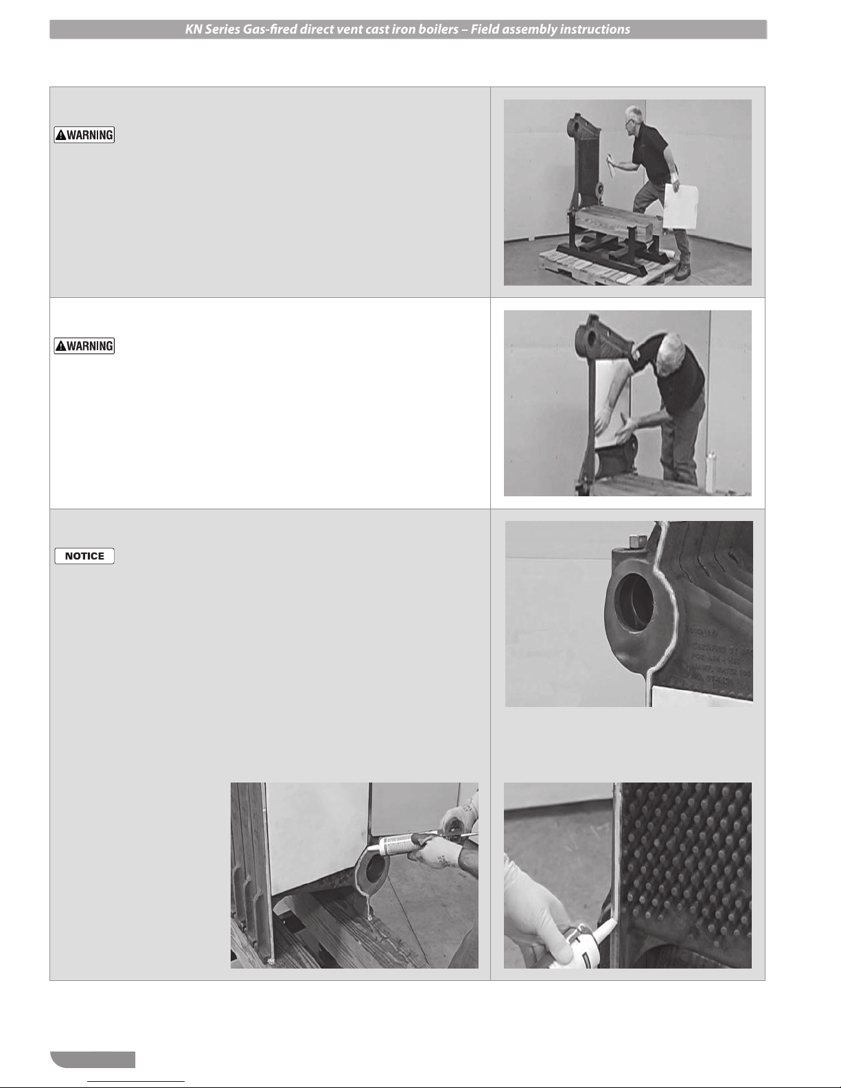
Step 2 Oil top surface of runner
boards
1. Use a brush to spread 30-wt motor
oil on the runner boards. This will
allow sections to move easily during
draw-up.
1. Remove base from skid.
2. Place a 4x6 board (supplied) against
each side as a runner shown.
3. Space runner boards with about even
amounts off of each end of the base.
4. The runner boards will be used to
support the boiler block during assembly, then removed afterward.
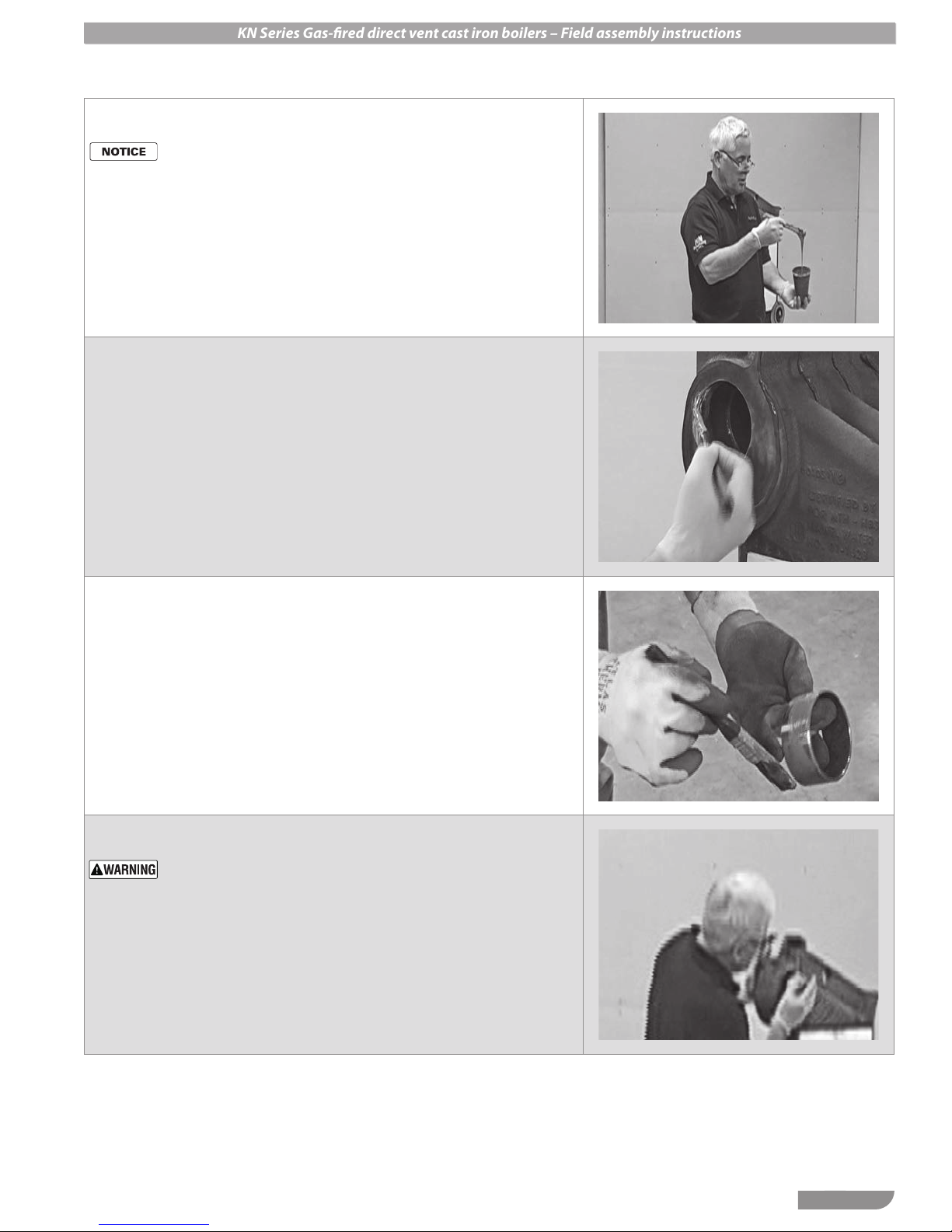
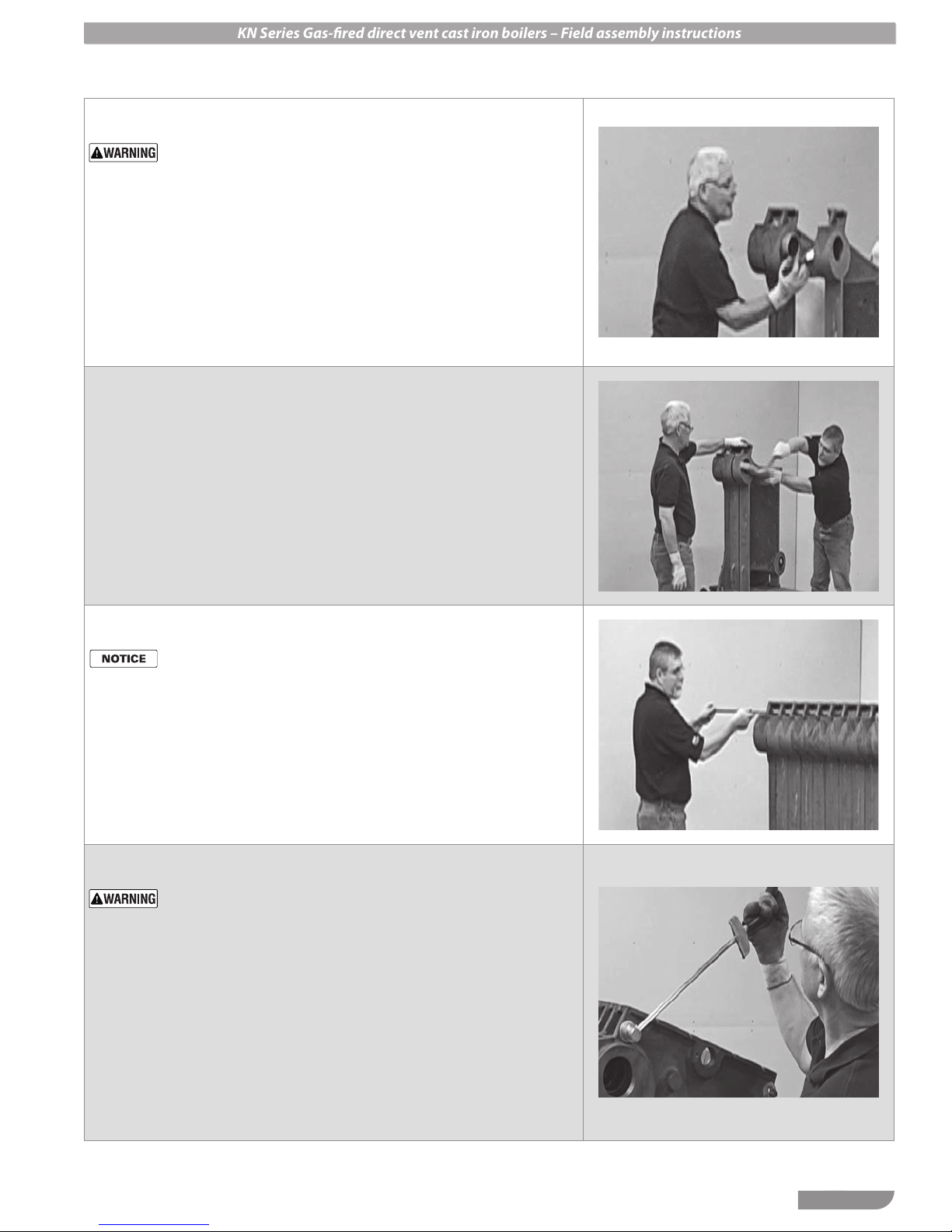
Step 3 Position the rear section
Use leather gloves when li-
ing or moving boiler sections.
Sections are heavy and can
cause severe personal injury
or death if mishandled.
Li section using two
people, following the
recommendations shown in
Step13,page8.
Step 4 Bolt rear section to base
1. Use 3/8 x 3½” bolts, wedges, split
lock washer and nut on each side as
shown.
2. Point the wedge narrow edge toward
the section.
1. Identify the rear section — its lower
nipple port is on the right side when
looking at the inside of the section, as
in this photo.
2. Slide the rear section to the end of
the base. Have someone support the
section during the next step.
Tighten bolt rmly, but DO
NOT over-tighten — the
cast iron ange could be broken if too tight. Tighten only
until the split lock washer has
just aened.
P/N 42-9551
5
KN Series Gas-fired direct vent cast iron boilers – Field assembly instructions
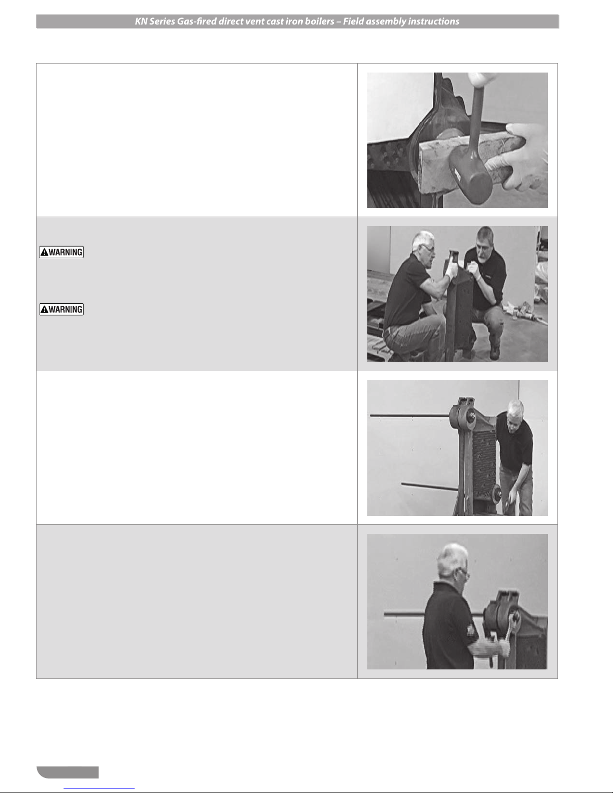
Step 5 Prepare section for baffle
Use of an approved dust
respirator is strongly recommended when handling the
insulating components of the
boiler.
Step 6 Install baffle
Do not use baes if they
have been broken, cracked,
folded or frayed. Obtain replacements before proceeding with the boiler assembly.
Step 7 Apply RTV to perimeter
1. Spray cast iron heat pin section liberally with spray adhesive supplied with
the boiler.
2. Avoid spraying on the nipple port
machined surfaces.
1. Place a baffle in the heat pin area of
the front section as shown.
2. The cut-off corner must go to the
lower right.
3. Press into place.
4. Make sure the baffle does NOT
overlap onto the perimeter surfaces
of the section. This would prevent the
section from drawing up correctly.
Rubber gloves are recom-
mended for this procedure.
1. Apply a bead of silicone RTV (supplied with boiler) on the perimeter
surfaces of the section and around
the INSIDE edges of the nipple ports.
2. This is necessary to form a seal between the sections. The seal prevents
flue gases from escaping.
3. Extend the bead all the way from the
top of the section to the bottom.
4. Keep the bead of silicone close to the
INSIDE edge of the nipple ports.
5. This will protect the machined nipple
port surfaces from condensation that
may occur in the flueways.
6
P/N 42-9551
KN Series Gas-fired direct vent cast iron boilers – Field assembly instructions
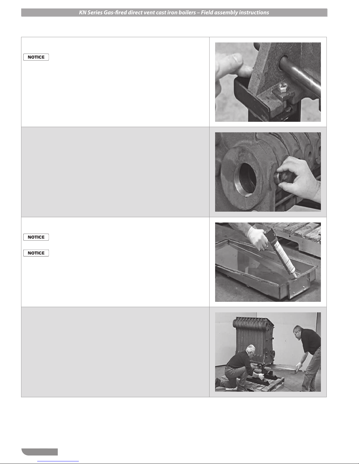
Step 8 Push nipple lubricant
Rubber gloves are recom-
mended for this procedure.
Step 9 Lubricate nipple ports
Step 10 Lubricate push nipples
1. In a disposable container, mix some
30-wt motor oil with some of the
Hercules Pro Dope supplied with the
boiler.
2. The consistency should be similar to
thick paint and should flow easily.
3. You will need enough to lubricate all
nipple ports and all push nipples —
probably about ½ pint is enough.
1. Brush the pipe dope/oil mixture on
the inner machined surfaces of the
nipple ports.
2. Avoid getting lubricant on the silicone RTV or on the face of the nipple
ports.
Step 11 Insert push nipples
Avoid scarring or damaging
the push nipple or nipple
port surfaces. e push nipple makes a metal-to-metal
seal with the nipple port. Any
surface defects could cause a
leak.
1. Brush the entire outside surface of
each nipple port with the lubricant.
1. Insert a push nipple into each of the
two nipple ports.
2. Seat each nipple firmly but squarely.
3. Make sure the nipple face is parallel
to the section surface as closely as
possible.
4. DO NOT attempt to assemble sections if any nipple port is mis-aligned.
P/N 42-9551
7
KN Series Gas-fired direct vent cast iron boilers – Field assembly instructions
Step 12 Seat the push nipples
Step 13 Lifting the sections
1. Place a 2x4 board across the nipple
and strike firmly with a mallet.
2. Do this with several strokes, just so
the push nipple is firmly started.
3. Make sure the board is parallel to the
nipple port surface to prevent rolling
the push nipple.
Use leather gloves when li-
ing or moving boiler sections.
Sections are heavy and can
cause severe personal injury
or death if mishandled.
Li section using two
people, following the
recommendations shown in
Step13,page8.
Step 14 Draw up sections
1. Carefully slide the first intermediate
section up to the front.
2. Before pulling the intermediate
section up fully, brush lubricant on
the inside machined surfaces of the
nipple ports as in Step 9, page 7.
3. Use a 2x4 board and mallet to start
the section in place as shown in
Step 17, page 9.
Step 15 Pull sections together
1. Lift section, with each person holding
at the bottom of the section.
2. Handlers should lift with their legs to
avoid back strain.
4. Wipe a small amount of motor oil on
the ¾-inch all-thread rods supplied
with the boiler to make pull-up easier.
5. Place a ¾” nut and washer plus a cast
iron plate (supplied with boiler) on
the ¾” rod on each side as shown.
6. Snug finger tight.
1. Use box wrenches (preferred) to pull
2. Alternate from one side to the other
3. When the sections are properly
8
the sections together.
during pull-up to avoid cocking the
nipple ports.
pulled up, they will be nearly metalto-metal.
P/N 42-9551
KN Series Gas-fired direct vent cast iron boilers – Field assembly instructions
Step 16 Install baffle
Do not use baes if they
have been broken, cracked,
folded or frayed. Obtain replacements before proceeding with the boiler assembly.
Step 17 Use 2x4 and mallet
1. Before adding additional sections,
install a baffle in the flueway as in
Step 5, page 6 and Step 6, page 6.
2. Place a baffle in the heat pin area of
the front section as shown.
3. The cut-off corner must go to the
lower right.
4. Press into place.
5. Make sure the baffle does NOT
overlap onto the perimeter surfaces
of the section. This would prevent the
section from drawing up correctly.
1. To initially seat the push nipple into
the next section, rap with a mallet
and 2x4 at each nipple port.
2. Repeat, alternating from right nipple
port to left to avoid cocking the push
nipples.
Step 18 Install draw rods
e draw rods ARE NOT
used to pull the sections
together, only to keep them
rmly in position.
Step 19 Use a torque wrench
DO NOT exceed 30foot-
pounds when tightening
nuts. Higher torque could
cause breakage of the cast
iron.
1. When the section assembly is completed, slide a draw rod through each
of the four draw rod holes.
2. Apply a washer and nut on each end
and pull up finger tight.
1. Use a torque wrench to tighten the
nuts on the draw rods.
2. Start with the upper left corner rod
first.
3. Tighten the nut to 15 foot-pounds.
4. Move to the lower right rod. Tighten
the nut to 15 foot-pounds.
5. Repeat with the lower left, then the
upper right rod, both tightened to
15 foot pounds.
6. Repeat this sequence again, but finish
the tightening to 30 foot-pounds for
each nut.
P/N 42-9551
9
KN Series Gas-fired direct vent cast iron boilers – Field assembly instructions
Step 20 Bolt boiler to base
Before bolting the boiler to
the base, knock the two 4x6
boards out from under the
block. If necessary, loosen the
two bolts that secure the back
section to the base.
Step 21 Inspection port plugs
Step 22 Prepare condensate pan
1. Install a bolt, wedge, washer and nut
on side of the front section as done in
Step 4, page 5.
2. Tighten only until the split lock
washer has just flattened.
3. Make sure the back section bolts are
tightened as well.
1. Apply pipe dope (supplied with
boiler) to plugs (supplied) and install
in each of the inspection ports at the
lower right side of each section.
Rubber gloves are recom-
mended for this procedure.
e condensate drain pan
is shown here with the
inspection plate and gasket
installed. is can be done
before or aer the condensate drain pan is bolted to the
boiler.
Step 23 Install condensate drain
pan
1. This procedure requires two people
to do correctly.
2. Guide the condensate drain pan
through the front of the base as
shown.
3. When in position, lift the pan straight
up and hold firmly against the bottom of the section assembly.
1. Use the silicone RTV supplied with
the boiler to apply a bead on the
condensate pan flange around the
complete perimeter.
2. At each of the four corners, apply a
bead on the flange where the sheet
metal edges meet.
4. Install each bolt with two flat washers,
one split lock washer and nut (provided). Insert the bolts from the top.
5. Tighten just until the split lock washer
has flattened.
10
P/N 42-9551
 Loading...