

HydroTherm KN-16, KN-26, KN-30 Field Assembly Instructions

KN-FAI2-0313
Gas-Fired Cast Iron Boilers
42-9552
Models
KN-16, -26, and -30
Field Assembly
Instructions
Also read and follow:
KN Series Gas Boiler
Installation and Operating
Instructions
and
KN HeatNet Control Manual
is manual is intended only for use by a quali ed heating installer/technician. Read and follow this manual, all supplements and related
instructional information provided with the boiler. Install, start and service the boiler only in the sequence and methods given in these
instructions. Failure to do so can result in severe personal injury, death or substantial property damage.
Do not use the boiler during construction. Construction dust and particulate, particularly drywall dust, will cause contamination of
the burner, resulting in possible severe personal injury, death or substantial property damage. e boiler can only be operated with a dustfree air supply. Follow the instruction manual procedures to duct air to the boiler air intake. If the boiler has been contaminated by operation
with contaminated air, follow the instruction manual guidelines to clean, repair or replace the boiler if necessary.
A x these instructions near to the boiler/water heater. Instruct the building owner to retain the instructions for future use by a quali ed
service technician, and to follow all guidelines in the User’s Information Manual.
10/12 Copyright 2010 Hydrotherm

G
as-Fired Direct Vent Cast Iron Boilers – Field Assembly Instruction
s
INFORMATION
This manual is intended only for the fi eld assembly of
a KN-16, -26 or -30 boiler. Follow the assembly
instructions in sequence. Also follow all requirements
of the KN Boiler manual and the KN HeatNet manual.
BLOCK ASSEMBLY SEQUENCE
These instructions show block assembly
beginning with the front section and fi nishing
with the back section.
If job conditions make this impractical, the bloc k
can be built beginning with the back section and
fi nishing with the front.
Hazard Icons
You will fi nd the following icons throughout this manual.
(English/French)
The WARNING icon indicates a hazard that
can cause severe personal injury, death or
substantial property damage.
The CAUTION icon indicates a hazard that
will or can cause minor personal or property
damage.
The NOTICE icon calls out special instructions
that are important, but are not related to hazards.
READ BEFORE PROCEEDING
Customer Service And Technical Support
Direct all questions to your HydroTherm distributor or
contact the HydroTherm Customer Service Department at:
260 North Elm Street, Westfi eld, MA 01085. Always include
the model and serial numbers from the rating plate of the
boiler in question.
Claims for damage or missing components must be fi led
immediately against the transportation company by the
consignee.
CODES AND STANDARDS
Code compliances
All aspects of the boiler installation must conform to the
requirements of the authority having jurisdiction, or, in the
absence of such requirements, to the National Fuel Gas
Code, ANSI Z223.1/NFP A 54-latest re vision. Where required
by the authority having jurisdiction, the installation must
conform to the Standard for Controls and Safety Devices
for Automatically Fired Boilers, ANSI/ASME CSD-1.
In Canada, the installation must be in accordance with the
requirements of CSA B149.1 or .2, Installation Code for
Gas Burning Appliances and Equipment.
BEFORE ASSEMBLING THE BOILER . . .
Other Manuals
You must read and follow this manual, the KN
Series Gas Boiler Installation and Operating
Instructions, the KN HeatNet Control manual
and all additional materials supplied with the
boiler. Failure to do so can result in severe
personal injury, death or substantial property
damage.
Boiler/Control Installation And Setup
After completing assembly of the KN boiler, follow all
instructions in the Installation and Operation Instructions
and Control Manual for installation, start-up and testing.
Verify Boiler Rating And Gas Supply
• Before assembling and installing the boiler, check the
ratings to ensure that the unit has been sized properly
for the job.
• Ensure that the boiler will be set up for the type of gas
available at the installation site.
Verify Location Is Suitable
• Ensure the availability of an adequate electrical supply,
uncontaminated air for combustion, and that vent (and
air) piping can be correctly installed.
• Ensure the boiler can be connected to system water
piping and gas supply.
• The boiler must not be exposed to dripping or spraying
water or to rain.
• If replacing an existing boiler, fi nd out what caused the
boiler to fail before installing a new boiler. Correct the
problems that led to failure, or the failure may happen
to the new boiler.
2

G
as-Fired Direct Vent Cast Iron Boilers – Field Assembly Instruction
s
ATTENTION:
Use of an approved dust respirator is
strongly recommended when handling the
insulating components of the boiler.
Electrical shock hazard — Disconnect all
electrical power sources to the boiler before
making any electrical connections.
Label all wires prior to disconnection when
servicing controls. Wiring errors can cause
improper and dangerous operation! Verify
proper operation after servicing.
Failure to comply with the abov e could result in
severe personal injury, death or substantial
property damage.
The electrical connections to this boiler must be
made in accordance with all applicable local
codes and the latest revision of the National
Electrical Code, ANSI /NFPA-70. Installation
should also conform to CSA C22.1 Canadian
Electrical Code Part I if installed in Canada.
Install a separate 120 volt 15 amp circuit for the
boiler. A properly rated shut-off switch should
be located at the boiler. The boiler must be
grounded in accordance with the authority
having jurisdiction, or if none, the latest revision
of the National Electrical Code, ANSI/NFPA-70.
Line voltage fi eld wiring of any controls or other
devices must use copper conductors with a
minimum size of #14 awg. Use appropriate
wiring materials for units installed outdoors.
DO NOT open any gas valve, or attempt to fi re
the boiler, until all boilers ha ve been set up and
verifi ed following the instructions in the KN
Series Gas Boiler Installation & Operating
Instructions.
Failure to comply could cause a boiler failure,
leading to possible severe personal injury,
death or substantial property damage.
COMPONENTS AND
SPECIAL TOOLS REQUIRED
Recommended Assembly Crew
The assembly crew should be a minimum of
3experienced technicians.
Equipment/Materials Required For Assembly
1. One quart 30-wt motor oil
2. Flexible leather work gloves
3. Dead-blow hammer with plastic face (DO NOT use a
sledge hammer)
4. Four 2" x 4" x 12" boards (used for cushioning when
seating push nipples)
5. Two 18 inch pipe wrenches (plus 2 inch x 2 feet
cheater pipe)
6. Crescent wrenches, 18 inch or larger, may be used for
tightening the draw rod nuts (NOT tie rods). (See
Step 16, page 10 for draw rod instructions.)
7. Torque wrench (at least 30 foot-pound capacity)
8. Deep socket, 11/16 inch for use with torque wrench
9. Standard hand tools.
10. Wire, wire nuts, electrical hand tools (crimper , stripper,
etc.).
Boiler Components And Shipping Information
Check the contents of the skids against the
Bill of Materials/Checklist shipped with the
boiler. Use the Checklist to locate specifi c items
throughout the assembly process. Content
your Hydrotherm supplier if you discover any
components damaged or missing.
The boiler is shipped in two skids and one crate. See the
contents of the crates and skids in Figure 2, page 23.
Sealants, lubricants and adhesives supplied with
boiler (see Figure 2, page 23 for location)
Use gloves when working with these products
as specified in these instructions and in the
product instructions.
1. Silicone RTV-6500 HiTemp: 10-oz caulk tubes (for
sealing between sections)
2. Loc-Tite 30557 pipe dope: (1) 16-oz can (for water and
gas piping connections)
3. Hercules Pro Dope: 8-oz jar (for mixing with 30-wt
motor oil, used as lubricant for push nipples)
4. Fast-Tack 87: (1) 13-oz spray can (for securing fl ue
baffl es to sections)
3
G
as-Fired Direct Vent Cast Iron Boilers – Field Assembly Instruction
s
FRONT END
(legs extend longer at
front than at rear)
REAR END
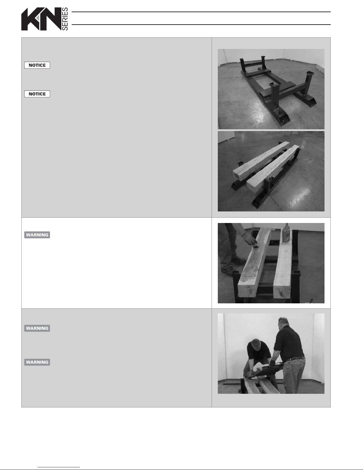
Step 1 Place runner beams on base (see BLOCK ASSEMBLY SEQUENCE NO-
TICE on page2 — assembly can be from back to front if necessary)
Make sure the boiler base is in the correct position before
starting. The legs extend longer on the FRONT end of the base
than on the rear end (approximately 9-1/2 inch at front and 6-3/4
inch at rear — use a tape measure if necessary to compare).
FRONT END
(legs extend longer at
front than at rear)
LOCATE BOILER TO
PROVIDE MINIMUM
CLEARANCES FOR
ASSEMBLY AND AS
REQUIRED BY KN BOILER
MANUAL:
e boiler must be installed
in accordance with the KN
Instruction Manual — the
boiler location must maintain
all required clearances for
service and spacing from
combustible surfaces.
In addition, provide:
AT LEAST 60 INCHES
clearance at the front of
the boiler to allow room for
block and condensate pan
assembly.
Step 2 Oil top surface of runner beams
DO NOT allow oil to drip
on the oor
Make sure the oor is free
of any slick spots and that
there is no debris or any
obstruction in the work area
or walk path to boiler parts.
.
1. Remove base from skid.
2. The base is symmetrical, so either end
can be placed as the front end.
3. Place a beam (supplied) against each
side as a runner as shown at right.
4. The planed surface of the beam must
be on top.
5. If beam has any curvature, place the
beam with the curvature toward the
OUTSIDE of the frame.
6. Space runner beams with about even
lengths extending o of each end of
the base.
7. The runner beams will be used to
support the boiler block during
assembly, then removed afterward.
1. Use a paint brush to spread 30-wt
motor oil on the runner boards. This
allows sections to move easily during
draw-up.
REAR END
Step 3 When lifting the sections
Use leather gloves when
li ing or moving boiler
sections. Sections are heavy
and can cause severe personal
injury or death if mishandled.
Lift section using two
people. Then place in
position on the runner
beams. Make sure
the section is always
supported to prevent
tipping or falling.
4
1. Lift section with each person lifting at
the bottom of the section.
2. Move onto the runners and slide into
position.
3. Handlers should lift with their legs to
avoid back strain.

G
as-Fired Direct Vent Cast Iron Boilers – Field Assembly Instruction
s
.
3. The adhesive is required to secure th
e
y
.
Step 4 Place the FRONT section
Use leather gloves when
li ing or moving boiler
sections. Sections are heavy
and can cause severe personal
injury or death if mishandled.
Have someone support the
section during this step and
the next. e sections are
top-heavy and could easily
fall if not supported.
Handle all sections with
care to prevent any
damage to machined
surfaces.
Step 5 Bolt front section to base
1. Use a 3/8 x 6 inch bolt, wedge, at
washer, split lock washer and nut on
each side as shown.
2. Point the wedge narrow edge toward
the section.
1. Identify the FRONT section — its
lower nipple port is on the LEFT side
when looking at the inside of the
section, as in this photo.
2. Slide the front section to the end of
the base.
3. Lift into position and have someone
hold securely.
Tighten bolt rmly, but DO
NOT over-tighten — the
cast iron ange could be
broken if too tight. Tighten
only until the split lock
washer has just a ened.
e bolt must be secure to
Wedge —
Point thin edge
toward the section.
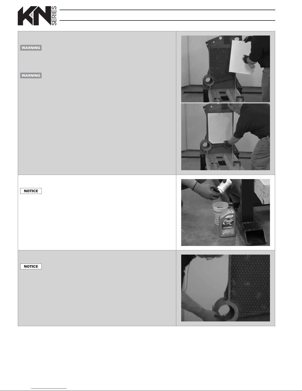
Step 6 Apply adhesive for ceramic ber ue ba e
DO NOT SPRAY adhesive
on the nipple port
machined surfaces
. is
would prevent proper sealing
with the silicone sealant
applied later.
1. Obtain the spray adhesive supplied in
the hardware box.
2. Spray ONLY the heat pin area of the
casting with the spray adhesive.
3. The adhesive is required to secure the
ue ba e (next step) in the ueway.
ue ba e (next step) in the uewa
prevent movement of the
front section during the next
steps of assembly.
5
G
as-Fired Direct Vent Cast Iron Boilers – Field Assembly Instruction
s
Step 7 Place ceramic ber ba e in ueway
Use of an approved dust
respirator is strongly
recommended when
handling the insulating
components of the boiler.
Do not use ue ba es if
they have been broken,
cracked, folded or frayed
Obtain replacements before
proceeding with the boiler
assembly.
1. The cut-o corner of the ba e must
go to the lower left corner. Align the
ba e in this position to determine
which side to spray with adhesive.
2. Apply spray adhesive to the back side
of a ceramic ber ba e.
3. Place the ba e in the heat pin area of
the front section as shown.
.
4. Press ba e into place.
5. Position the ba e so that it does
NOT overlap onto the edge
surfaces of the section. This would
prevent the section from drawing up
correctly.
Step 8 Mix push nipple lubricant
Work gloves are
recommended for this
procedure.
Step 9 Lubricate nipple ports
DO NOT get oil on the
FACES of the nipple ports
— apply lightly and ONLY
on the inside machined
surfaces.
If oil gets on a port face, wipe
o with a clean rag dipped
in a solvent such as mineral
spirits. Oil will prevent the
silicone sealant from sealing
properly.
1. In a disposable container, mix some
30-wt motor oil with some of the
Hercules Pro Dope supplied with
the boiler. Mix about 1part of oil to
20parts of the pipe dope.
2. The consistency should be similar to
thick paint and should ow easily.
3. You will need enough mixture to
lubricate all nipple ports and all push
nipples — about 1/2 pint.
1. Use a clean rag to wipe o all
machined surfaces on both sides
of the section before proceeding.
2. Also wipe clean the inside machined
surfaces of both nipple ports on fornt
and back of section.
3. After cleaning the ports, brush pipe
dope/oil mixture on the INNER
machined surfaces of the nipple ports
ONLY.
6
G
as-Fired Direct Vent Cast Iron Boilers – Field Assembly Instruction
s
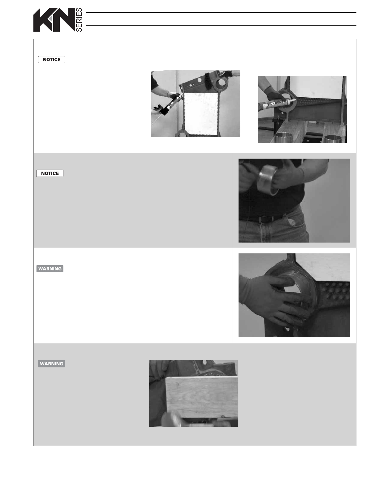
Step 10 Apply RTV to machined surfaces
Rubber gloves are
recommended for this
procedure.
1. Apply a bead of silicone RTV (supplied
with boiler) on the perimeter surfaces
of the section and around the INSIDE
edges of the nipple ports.
2. This is necessary to form a seal between
the sections. The seal prevents ue
gases from escaping.
3. Extend the bead all the way from the
top of the section to the bottom.
4. Keep the bead of silicone close to the
INSIDE edge of the nipple ports.
Step 11 Lubricate push nipples with oil/pipe dope mixture (see Step 8)
Inspect push nipples carefully
before using. DO NOT use
a nipple if it is gouged or
scarred.
DO NOT apply excessive
lubricant to the nipple
ports
. Lubricant can drip
onto the machined sealing
surface, preventing the
RTV sealant used later from
sticking.
1. Obtain two push nipples.
2. Inspect carefully and wipe o the
nipples with a clean cloth.
3. Brush the outside surface of each
push nipple VERY LIGHTLY with the
push nipple lubricant.
4. Wipe o any excess lubricant.
5. This will protect the machined nipple
port surfaces from condensation that
may occur in the ueways.
Step 12 Insert push nipples
Avoid scarring or damaging
the push nipple or nipple
port surfaces. e push
nipple makes a metal-tometal seal with the nipple
port. Any surface defects
could cause a leak.
Step 13 Seat the push nipples
Use only a dead blow hammer
to seat the push nipples. DO
NOT use a sledge hammer.
1. Place a 2x4 board across the nipple and
strike rmly with a dead-blow hammer.
2. Make sure to strike in the center of the
nipple to prevent rotating it.
3. Do this with several strokes, just so the
push nipple is rmly started.
1. Insert a push nipple into each of the
two nipple ports.
2. Seat each nipple rmly but squarely.
3. Make sure the nipple face is parallel
to the section surface as closely as
possible.
4. DO NOT attempt to assemble sections
if any nipple port is mis-aligned.
4. Look into the nipple ports from the end
of the boiler. When properly seated at
this point, the push nipple edge should
be slightly inside the nipple port. It
should also be parallel with the inside
surface.
7
G
as-Fired Direct Vent Cast Iron Boilers – Field Assembly Instruction
s
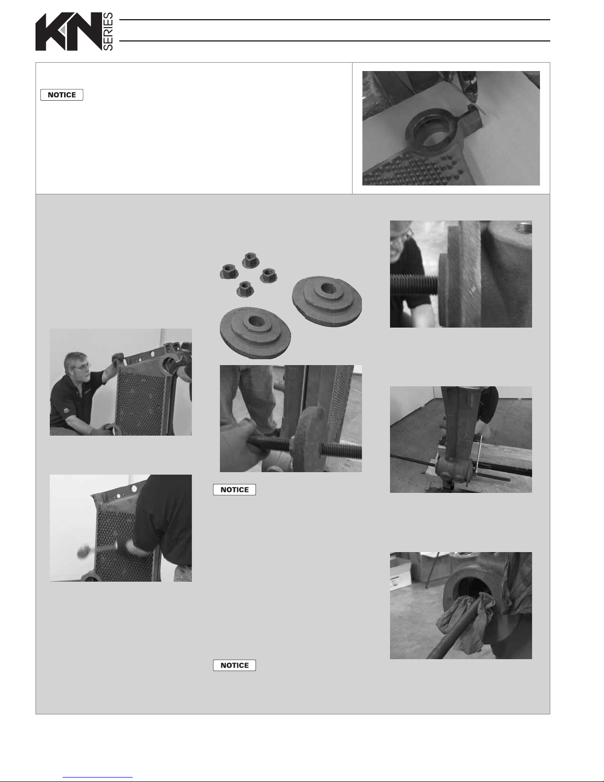
Bearing
plates
Place bearing plate with fl at side
away from the nut.
Step 14 File lower edges of next section
Work gloves are
recommended for this
procedure.
1. Use a at le to ease o the front
lower edge on both sides of the next
section.
2. This step will prevent the sharp edges
from gouging the runner beams as
the section is drawn up.
Step 15 Install next section and prepare draw rods
1. Carefully slide the rst intermediate
section up to the front.
2. Before pulling the intermediate section
up fully, clean the nipple ports and
brush lubricant on the inside machined
surfaces of the nipple ports as in Step9.
3. Align the intermediate section to the
front section and slowly move into
position so both push nipples just
enter the intermediate section.
nuts). The ribbed side of the bearing
plate (shown in the photo below) must
face the nut.
7/8-inch nuts and washers
Bearing
plates
Place bearing plate with fl at side
away from the nut.
11. Thread a washer and nut onto the
back end of each draw rod and snug
against the bearing plate. Make sure
the bearing plates are centered on the
nipple ports.
4. To initially seat the push nipple into the
next section, rap with a dead blow
hammer and 2x4 at each nipple port.
5. Repeat, alternating from right nipple
port to left to avoid cocking the push
nipples.
6. Wipe a small amount of motor oil on
the 7/8 inch all-thread rods supplied
with the boiler to make pull-up easier.
7. Place a 3/4 inch nut and washer plus
one of the bearing plates one each of
the two draw rods. The back sides (large
surface) of the bearing plates must face
toward the sections (away from the
When block assembly is
completed with the rear section,
use a small bearing plate on the
rear section as well, with the
ribs pointed inward.
8. Thread the nut far enough that about
24inches of draw rod extends beyond
the bearing plate.
9. Carefully insert the draw rods through
the front nipple ports. (Most of the draw
rod length will extend to the front.)
10. Slide one of the bearing plates over the
back end of each draw rod until ush
with the intermediate section port. The
bearing plate ribs should be toward the
nut, with at side against the section.
Hold the draw rods up while
positioning to prevent the draw
rod threads from gouging the
nipple port machine surfaces.
12. As additional sections are added, lay a
rag in the bottoms of the nipple ports
to prevent damaging the machined
surfaces as the draw rods are passed
through.
8
 Loading...