

HydroTherm HVX-70, HVX-105, HVX-140, HVX-165 Installation And Operating Instructions Manual
HydroTherrw
HVX2-810
22-HVX2
m
f
This inanual s intended only fbl use by aqualified beatinginstaller/technician Read and followthis manual, allsupplements and related
instructional infbrmation proxided with tile boiler. Install,start and ser;ice tile boiler only in tile sequence and inethods gixen ill these
instructions. Faihn:eto do so can result in sexere personal injury,death or substantial property damage.
Do not use the boiler during construction. Construction dust and particulate, particularlydrywalldust,willcausecontamination of
the burner, resulting in possible sexere personal injury,death orsubstantial property damage. The boiler can only be operated with adust-
fi'eeair supply.Followthe instruction manual procedures to duct air to the boiler airintake. Ifthe boilerhas been contaminated byoperation
with contaminated air,fbllow the instruction manual guidelines to clean,repair or replace the boiler ifnecessary.
Affixthese instructions near to the boile,,,'water heate, lnst,uct the buikting owner to retain the instructions ibr ihture use by a qualified
servicetechnician, and to fbllowallguidelines in the User's Infbrmation Manual.
INSTALLATION AND OPERATING INSTRUCTIONS
A. INSTALLATION SEQUENCE ....................... 2
B. SPECIAL ATTENTION BOXES ..................... 2
,,
A. ACCESSIBILITY CLEARANCES .................... 3
B. CLEARANCE FROM COMBUSTIBLE
CONSTRUCTION ................................ 3
C. AIR FOR COMBUSTION AND VENTILATION ......... 3
D. PLANNING THE LAYOUT ......................... 6
E. MASSACHUSETTS INSTALLATIONS ............... 6
A. BOILER SUPPLY AND RETURN .................... 8
B. SAFETY RELIEF VALVE .......................... 9
C. PIPING FOR ZONED SYSTEMS ................... 10
D. EXPANSION TANK ............................. 11
E. INDIRECT-FIRED WATER HEATER ................. 11
E FREEZE PROTECTION .......................... 11
A. GENERAL .................................... 12
B. CHIMNEY VENTING ............................ 12
C. DIRECT EXHAUST HORIZONTAL VENTING ......... 12
D. DIRECT EXHAUST VERTICAL VENTING ............ 15
E. BOILER REMOVAL FROM
COMMON VENTING SYSTEM .................... 16
i iiiiiili:i !! i iii:i i i Ii Ii Ii Ii Ii Ii Ii Ii Ii Ii Ii Ii Ii Ii Ii Ii Ii Ii Ii Ii Ii Ii Ii Ii Ii Ii Ii Ii Ii Ii Ii Ii Ii Ii Ii Ii Ii Ii Ii Ii Ii Ii Ii Ii ! ii! 7iii
A. GENERAL .................................... 30
B. DAILY (WITH BOILER IN USE) .................... 30
C. WEEKLY (WITH BOILER IN USE) .................. 31
D. MONTHLY (WITH BOILER IN USE) ................ 31
E. ANNUALLY (BEFORE START OF HEATING
SEASON) ..................................... 31
A. BLOCK/BASE/FLOOR PAN
JACKET/FLUE COLLECTOR ...................... 33
B. BASE/BURNERS/MANIFOLD ..................... 34
f:ll II_!.'tq.'lli!.'l/[o]_l _.'];[o].lJ!_[o,]!
Follow the installation instructions provided in this
manual in the order shown. The order of these
instructions has been set in order to provide the
installer with a logical sequence of steps that will
minimizepotential interferences and maximize safety
during boiler installation.
I:!1 [,-l'.l:l:l]llllfll//!_i/[o]_l I:{o):t_ _7
Throughout this manual you will see special attention
boxes intended to supplement the instructions and
make special notice of potential hazards. These
categories mean, in the judgment of the manufacturer:
A. WIRING ...................................... 19
B. ZONED SYSTEM WIRING ....................... 19
C. CONTROLS ................................... 19
D. SEQUENCE OF OPERATION ..................... 20
A. COMPLETING THE INSTALLATION ................ 23
B. CONTROL DESCRIPTIONS ....................... 25
C. ADJUSTMENT OF GAS PRESSURE REGULATOR .... 25
D. CHECKING BURNER INPUT ...................... 25
E. CHECK-OUT PROCEDURE ....................... 25
A. SHUT-DOWN CAUSED BY PILOT OUTAGE,
PRESSURE SWITCH OR FLAME ROLL-OUT
SAFETY SHUT-OFF SWITCH ..................... 27
B. TROUBLESHOOTING GUIDES .................... 27
C. MEASURING SUCTION PRESSURE ............... 27
Indicates a condition or hazard which will cause
severe personal injury, death or major property
damage.
Indicates a condition or hazard which may cause
severe personal injury, death or major property
damage.
Indicates a condition or hazard which will or can
cause minor personal injury or property damage.
Indicates special attention is needed, but not directly
related to potential personal injury or property
damage.
2
INSTALLATION AND OPERATING INSTRUCTIONS
Read carefully, study these instructions before beginning work.
This boiler must be installed by a qualified contractor.
The boiler warranty can be voided if the boiler is not installed, maintained and serviced correctly.
The equipment must be installed in accordance with those installation requirements of the authority having
jurisdiction or, in the absence of such requirements, to the current edition of the National Fuel Gas Code, ANSI
Z223.1/NFPA 54 and/or CAN/CSA B149.1, Natural Gas and Propane Installation Code.
Where required by the authority having jurisdiction, the installation must conform to American Society of
Mechanical Engineers Safety Code for Controls and Safety Devices for Automatically Fired Boilers,
ANSI/ASME CSD-I.
7._I V.'I_H _'_11:] I! / L'd[_]! =!'.'I:!.'I_[_]_1
Install boiler not less than 24" (610 mm) between the
left side, top, and front of the boiler and adjacent wall or
other appliance, when access is required for servicing.
The design of this boiler is certified for closet installation
with the following clearances:
1. 6" (152 mm) between sides, rear and front and
combustible construction.
2. 24" (610 mm)between top of jacket and
combustible construction.
3. 2" (51 mm) between vent pipe and combustible
construction.
Do not install this boiler on combustible flooring
unless it is installed on a special combustible floor
pan provided by the manufacturer. Boiler installation
on combustible flooring without the special pan is a
fire hazard.
To order combustible floor pan, use the 5-digit stock
codes listed in Section 11 of this manual.
Do not install this boiler on carpeting. Boiler
installation on carpeting is a fire hazard. Install this
boiler on non-combustible flooring or use a
combustible floor pan to install this boiler on other
non-carpeted flooring.
1.
Adequate combustion air and ventilation air must be
provided in accordance with section 5.3, Air for
Combustion and Ventilation, of the National Fuel
Gas Code, ANSI Z223.1/NFPA 54, or Sections 7.2,
7.3 or 7.4 of CAN/CSA B149.1, Natural Gas and
Propane Installation Code or applicable provisions of
the local building code. Subsections 2 through 8 as
follows are based on the National Fuel Gas Code
requirements.
2.
Required Combustion Air Volume: The total required
volume of indoor air is to be the sum of the required
volumes for all appliances located within the space.
Rooms communicating directly with the space in
which the appliances are installed and through
combustion air openings sized as indicated in
Subsection 3 are considered part of the required
volume. The required volume of indoor air is to be
determined by one of two methods.
a. Standard Method: The minimum required
volume of indoor air (room volume) shall be 50
cubic feet per 1000 BTU/Hr (4.8 m3/kW). This
method is to be used if the air infiltration rate is
unknown or if the rate of air infiltration is known
to be greater than 0.6 air changes per hour. As
an option, this method may be used if the air
infiltration rate is known to be between 0.6 and
0.4 air changes per hour. If the air infiltration rate
is known to be below 0.4 then the Known Air
Infiltration Rate Method must be used. If the
building in which this appliance is to be installed
is unusually tight, we recommend that the air
infiltration rate be determined.
b. Known Air Infiltration Rate Method: Where
the air infiltration rate of a structure is known, the
minimum required volume of indoor air for the
boiler and other fan assisted appliances shall be
determined as follows:
Required Volumerar7i 15 ft3 / rat7
AC H 1o00BtU/hr
INSTALLATION AND OPERATING INSTRUCTIONS
where:
It_n = Input of the fan assisted appliances in
ACH = air change per hour (percent of the
For appliances other than fan assisted, calculate
the required volume of air using the following
equation:
Required Volumeother = ACH lO00BtU/hr
Btu/hr
volume of the space exchanged per
hour, expressed as a decimal)
21 ft-s I other
Iother = Input of appliances other than fan
assisted in Btu/hr
Note: These calculations are not to be used for
infiltration rates greater than 0.60 ACH.
3.
Indoor Air Openinq Size and Location: Openings
connecting indoor spaces shall be sized and located
as follows:
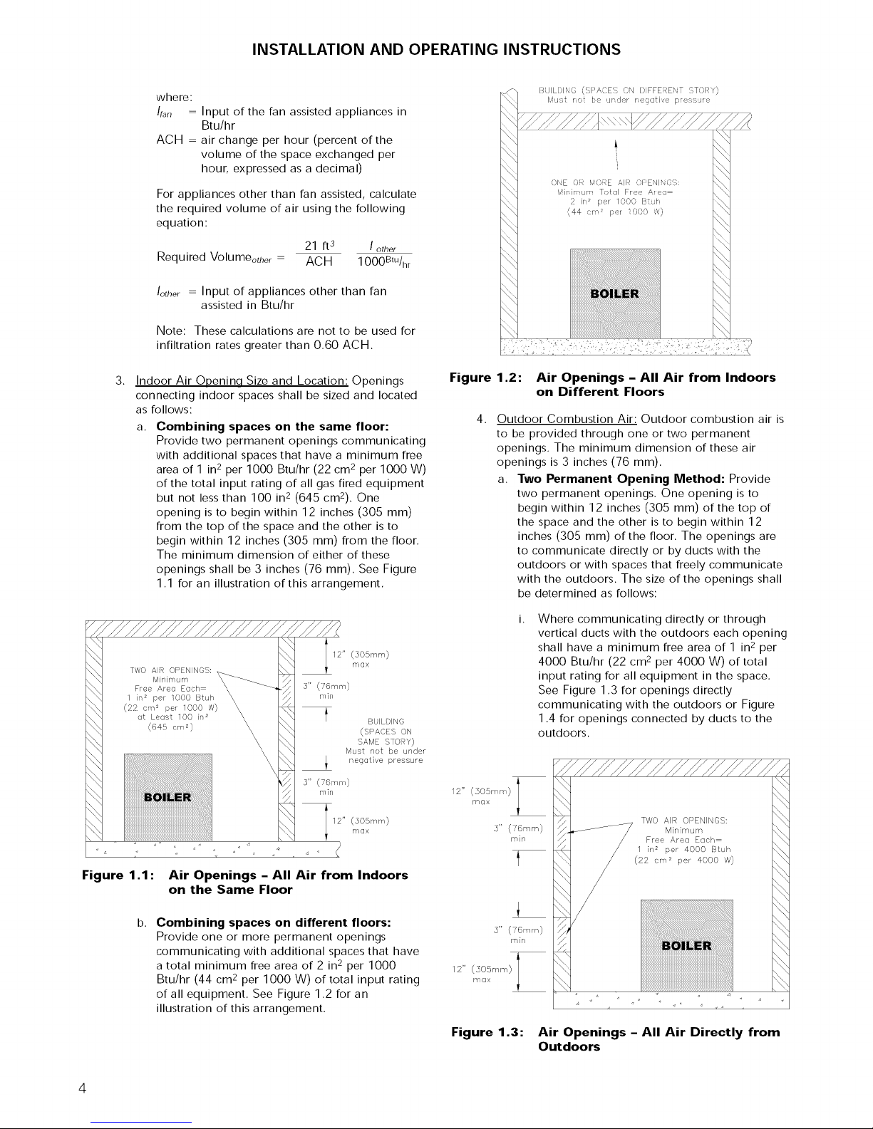
a. Combining spaces on the same floor:
Provide two permanent openings communicating
with additional spaces that have a minimum free
area of 1 in 2 per 1000 Btu/hr (22 cm 2 per 1000 W)
of the total input rating of all gas fired equipment
but not less than 100 in 2 (645 cm2). One
opening is to begin within 12 inches (305 mm)
from the top of the space and the other is to
begin within 12 inches (305 mm) from the floor.
The minimum dimension of either of these
openings shall be 3 inches (76 mm). See Figure
1.1 for an illustration of this arrangement.
12" (305mrs')
TWO AIR OPENINGS:
Minimum
Free Area Each
1 in 2 per 1000 Btuh
(22 errF per 1000 W)
at Least 100 in 2
(645 cm 2 )
4
s" (Turin)
min
3" (76ram)
rain
12" 505rr r_')max
m(lx
BUILDING
(SPACES ON
SAME STOU)
Must not be under
negative pressure
Figure 1.2:
4.
Outdoor Combustion Air: Outdoor combustion air is
to be provided through one or two permanent
openings. The minimum dimension of these air
openings is 3 inches (76 mm).
a. Two Permanent Opening Method: Provide
12" (505rr'm)maxi
Air Openings - All Air from Indoors
on Different Floors
two permanent openings. One opening is to
begin within 12 inches (305 mm) of the top of
the space and the other is to begin within 12
inches (305 mm) of the floor. The openings are
to communicate directly or by ducts with the
outdoors or with spaces that freely communicate
with the outdoors. The size of the openings shall
be determined as follows:
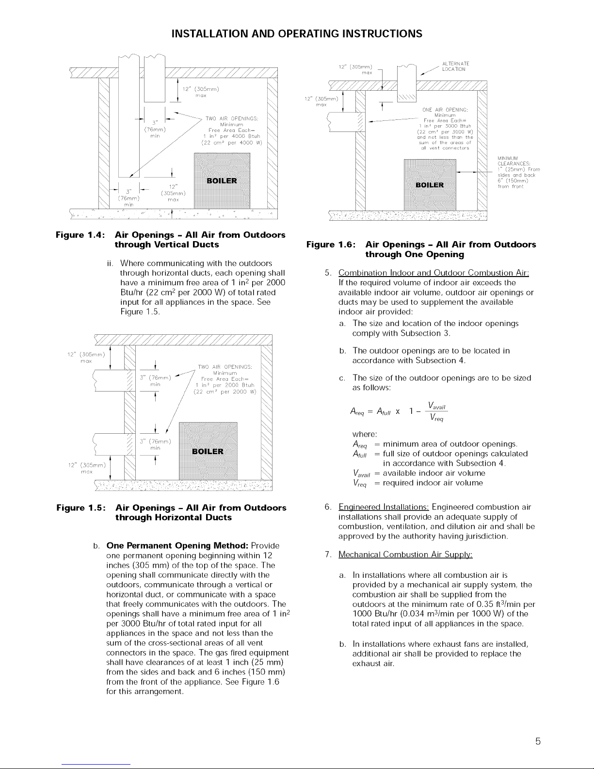
Where communicating directly or through
vertical ducts with the outdoors each opening
shall have a minimum free area of 1 in2 per
4000 Btu/hr (22 cm 2 per 4000 W) of total
input rating for all equipment in the space.
See Figure 1.3 for openings directly
communicating with the outdoors or Figure
1.4 for openings connected by ducts to the
outdoors.
\
\,
\ \,
Figure 1.1 :
Air Openings - All Air from Indoors
on the Same Floor
b.
Combining spaces on different floors:
Provide one or more permanent openings
communicating with additional spaces that have
a total minimum free area of 2 in2 per 1000
Btu/hr (44 cm 2 per 1000 W) of total input rating
of all equipment. See Figure 1.2 for an
illustration of this arrangement.
4
3" (76rnm)
12" (305ram)
too×
Figure 1.3:
........iiiiiiii
rain
Air Openings - All Air Directly from
Outdoors
INSTALLATION AND OPERATING INSTRUCTIONS
12" (505r r)rax I
z
(
MINIM JM
CLEARANCES:
" (P r/r ) Fr rY
_ides qrd back
6" (/5( rYr 0
frorr frort
Figure 1.4:
12" (:SO5r r)r_ax I
Figure 1.5:
Air Openings - All Air from Outdoors
through Vertical Ducts
ii,
Where communicating with the outdoors
through horizontal ducts, each opening shall
have a minimum free area of 1 in2 per 2000
Btu/hr (22 cm 2 per 2000 W) of total rated
input for all appliances in the space. See
Figure 1.5.
Air Openings - All Air from Outdoors
through Horizontal Ducts
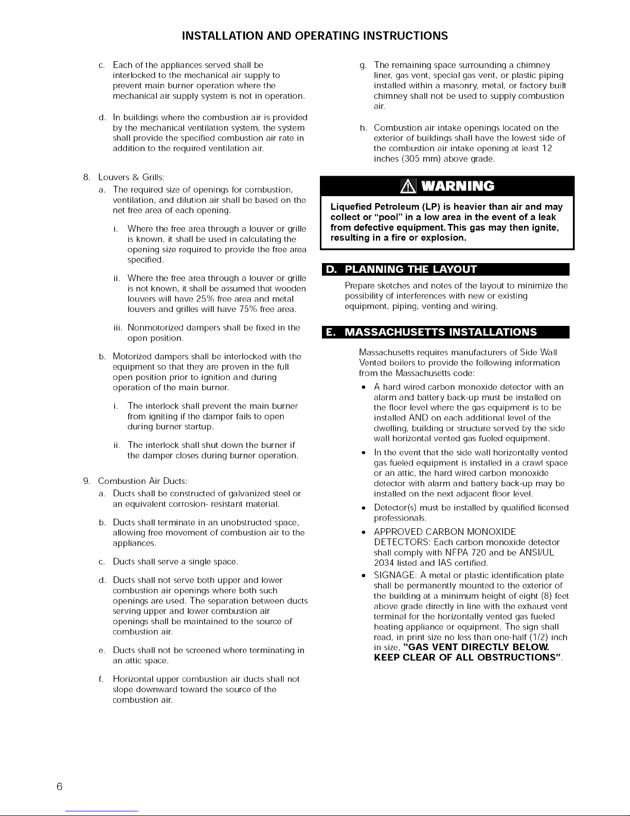
b.
One Permanent Opening Method: Provide
one permanent opening beginning within 12
inches (305 mm) of the top of the space. The
opening shall communicate directly with the
outdoors, communicate through a vertical or
horizontal duct, or communicate with a space
that freely communicates with the outdoors. The
openings shall have a minimum free area of 1 in 2
per 3000 Btu/hr of total rated input for all
appliances in the space and not less than the
sum of the cross-sectional areas of all vent
connectors in the space. The gas fired equipment
shall have clearances of at least 1 inch (25 mm)
from the sides and back and 6 inches (150 mm)
from the front of the appliance. See Figure 1.6
for this arrangement.
Figure 1.6: Air Openings - All Air from Outdoors
through One Opening
5. Combination Indoor and Outdoor Combustion Air:
If the required volume of indoor air exceeds the
available indoor air volume, outdoor air openings or
ducts may be used to supplement the available
indoor air provided:
a. The size and location of the indoor openings
comply with Subsection 3.
b. The outdoor openings are to be located in
accordance with Subsection 4.
c. The size of the outdoor openings are to be sized
as follows:
Vavail
A,-eq=A_u// x 1- V,eq
where:
Areq = minimum area of outdoor openings.
Atull = full size of outdoor openings calculated
in accordance with Subsection 4,
V_vail = available indoor air volume
Vreq = required indoor air volume
6.
Engineered Installations: Engineered combustion air
installations shall provide an adequate supply of
combustion, ventilation, and dilution air and shall be
approved by the authority having jurisdiction.
7. Mechanical Combustion Air Supply:
a. In installations where all combustion air is
provided by a mechanical air supply system, the
combustion air shall be supplied from the
outdoors at the minimum rate of 0.35 ftS/min per
1000 Btu/hr (0.034 mS/min per 1000 W) of the
total rated input of all appliances in the space.
b. In installations where exhaust fans are installed,
additional air shall be provided to replace the
exhaust air.
INSTALLATION AND OPERATING INSTRUCTIONS
Each of the appliances served shall be
interlocked to the mechanical air supply to
prevent main burner operation where the
mechanical air supply system is not in operation.
d.
In buildings where the combustion air is provided
by the mechanical ventilation system, the system
shall provide the specified combustion air rate in
addition to the required ventilation air.
8.
Louvers & Grills:
a. The required size of openings for combustion,
ventilation, and dilution air shall be based on the
net free area of each opening.
Where the free area through a louver or grille
is known, it shall be used in calculating the
opening size required to provide the free area
specified.
ii.
Where the free area through a louver or grille
is not known, it shall be assumed that wooden
louvers will have 25% free area and metal
louvers and grilles will have 75% free area.
iii. Nonmotorized dampers shall be fixed in the
open position.
b.
Motorized dampers shall be interlocked with the
equipment so that they are proven in the full
open position prior to ignition and during
operation of the main burner.
i. The interlock shall prevent the main burner
from igniting if the damper fails to open
during burner startup.
ii. The interlock shall shut down the burner if
the damper closes during burner operation.
9.
Combustion Air Ducts:
a. Ducts shall be constructed of galvanized steel or
an equivalent corrosion- resistant material.
b.
Ducts shall terminate in an unobstructed space,
allowing free movement of combustion air to the
appliances.
c.
Ducts shall serve a single space.
d.
Ducts shall not serve both upper and lower
combustion air openings where both such
openings are used. The separation between ducts
serving upper and lower combustion air
openings shall be maintained to the source of
combustion air.
Ducts shall not be screened where terminating in
an attic space.
The remaining space surrounding a chimney
g.
liner, gas vent, special gas vent, or plastic piping
installed within a masonry, metal, or factory built
chimney shall not be used to supply combustion
air.
h.
Combustion air intake openings located on the
exterior of buildings shall have the lowest side of
the combustion air intake opening at least 12
inches (305 mm) above grade.
Liquefied Petroleum (LP) is heavier than air and may
collect or "pool" in a low area in the event of a leak
from defective equipment. This gas may then ignite,
resulting in a fire or explosion.
I,]il I',ji_':_l_ll_[_//:l:! I!':VL*IIJd
Prepare sketches and notes of the layout to minimize the
possibility of interferences with new or existing
equipment, piping, venting and wiring.
I_ hv_P';T,."_"]P';[o,]'LU_")_/n_Ih_(,."]iq±_iUlip'±_id[o]_(,."]
Massachusetts requires manufacturers of Side Wall
Vented boilers to provide the following information
from the Massachusetts code:
• A hard wired carbon monoxide detector with an
alarm and battery back-up must be installed on
the floor level where the gas equipment is to be
installed AND on each additional level of the
dwelling, building or structure served by the side
wall horizontal vented gas fueled equipment.
• In the event that the side wall horizontally vented
gas fueled equipment is installed in a crawl space
or an attic, the hard wired carbon monoxide
detector with alarm and battery back-up may be
installed on the next adjacent floor level.
• Detedor(s) must be installed by qualified licensed
professionals.
• APPROVED CARBON MONOXIDE
DETECTORS: Each carbon monoxide detector
shall comply with NFPA 720 and be ANSI/UL
2034 listed and IAS certified.
• SIGNAGE: A metal or plastic identification plate
shall be permanently mounted to the exterior of
the building at a minimum height of eight (8) feet
above grade directly in line with the exhaust vent
terminal for the horizontally vented gas fueled
heating appliance or equipment. The sign shall
read, in print size no less than one-half (1/2) inch
in size, "GAS VENT DIRECTLY BELOW.
KEEP CLEAR OF ALL OBSTRUCTIONS".
Horizontal upper combustion air ducts shall not
slope downward toward the source of the
combustion air.
6
INSTALLATION AND OPERATING INSTRUCTIONS
EXEMPTIONS to the requirements listed above:
o The above requirements do not apply if the
exhaust vent termination is seven (7) feet or
more above finished grade in the area of the
venting, including but not limited to decks
and porches.
o The above requirements do not apply to a
boiler installed in a room or structure separate
from the dwelling, building or structure used
in whole or in part for residential purposes.
See the latest edition of Massachusetts Code
248 CMR for complete verbage and also for
additional (non-vent related) requirements
(248 CMR is available online).
If your installation is NOT in Massachusetts, please
see your authority of jurisdiction for requirements
that may be in effect in your area. In the absence of
such requirements, follow the National Fuel Gas
Code, ANSI Z223.1/NFPA 54 and/or CAN/CSA
B149.1, Natural Gas and Propane Installation Code.
Venting System Installation Instructions - See
boiler manual and instructions provided with the
Venting System components. Additional copies may
be obtained from the Venting System Manufacturer
by visiting the following web addresses:
Heat-Fab - www.selkirkcorp.com/heatfab
Z-Flex - www.NovaFlex.com
Pro-Tech - www.protechinfo.com
MetaI-Fab - www.rntlfab.com
1.
Provide a sound, level foundation. Locate boiler as
near to the chimney or outside wall as possible and
centralized with respect to the heating system.
2.
Locate boiler in front of installation position before
removing crate.
3.
If using combustible floor pan, position pan on
foundation or flooring.
4.
Separate the wood shipping pallet from the boiler
base by removing two (2) hold-down bolts at each
end of the boiler base.
5.
Move boiler into final position. If using combustible
floor pan, install boiler on pan as outlined in the
instructions included with the pan.
INSTALLATION AND OPERATING INSTRUCTIONS
f.'1 I:{=] I I!=1:| [_llJ d d li'AV.'I_I=]I :_=l|lJ :__I
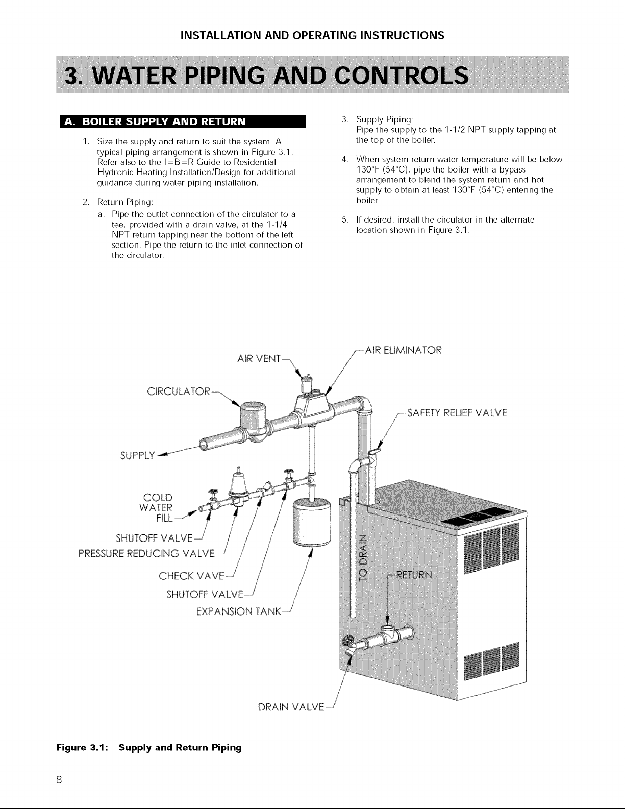
1.
Size the supply and return to suit the system. A
typical piping arrangement is shown in Figure 3.1.
Refer also to the I=B=R Guide to Residential
Hydronic Heating Installation/Design for additional
guidance during water piping installation.
2.
Return Piping:
a. Pipe the outlet connection of the circulator to a
tee, provided with a drain valve, at the 1-1/4
NPT return tapping near the bottom of the left
section. Pipe the return to the inlet connection of
the circulator.
3.
Supply Piping:
Pipe the supply to the 1-1/2 NPT supply tapping at
the top of the boiler.
4.
When system return water temperature will be below
130°F (54°C), pipe the boiler with a bypass
arrangement to blend the system return and hot
supply to obtain at least 130°F (54°C) entering the
boiler.
5.
If desired, install the circulator in the alternate
location shown in Figure 3.1.
SUPPLY
COLD
£R
SHUTOFF
PRESSUREREDUCING
CHECK
SHUTOFFVALVE
ELIMINATOR
_AFETYRELIEFVALVE
EXPANSION TANK
Figure 3.1: Supply and Return Piping
8
INSTALLATION AND OPERATING INSTRUCTIONS
6.
Install this boiler so that the gas ignition system
components are protected from water (dripping,
spraying, etc.) during appliance operation and
service (circulator replacement, condensate trap,
control replacements, etc.).
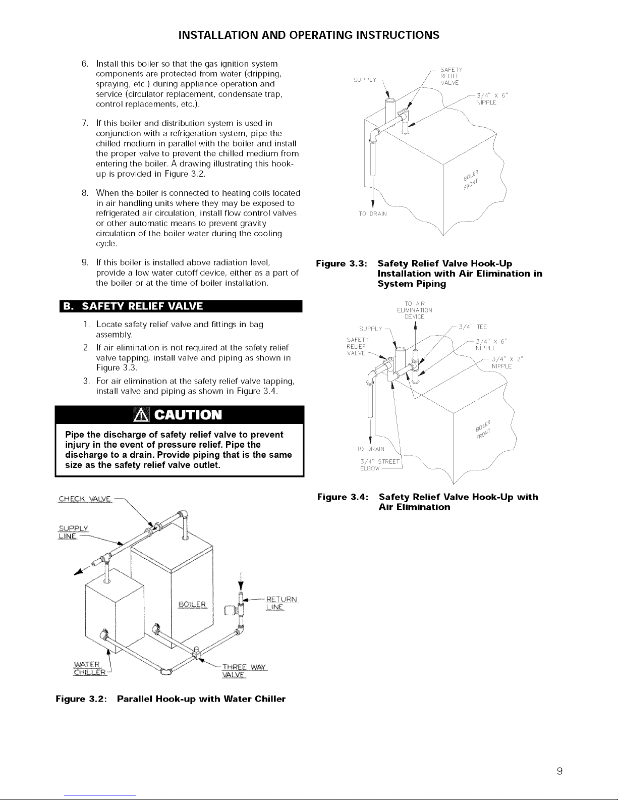
7.
If this boiler and distribution system is used in
conjunction with a refrigeration system, pipe the
chilled medium in parallel with the boiler and install
the proper valve to prevent the chilled medium from
entering the boiler. A drawing illustrating this hook-
up is provided in Figure 3.2.
8.
When the boiler is connected to heating coils located
in air handling units where they may be exposed to
refrigerated air circulation, install flow control valves
or other automatic means to prevent gravity
circulation of the boiler water during the cooling
cycle.
9.
If this boiler is installed above radiation level,
provide a low water cutoff device, either as a part of
the boiler or at the time of boiler installation.
SL PPLY -,
Figure 3.3:
....... SAFETY
RELIEF
'iALVE
TO DRAII
\
\
/
f_- -
/
/
Safety Relief Valve Hook-Up
Installation with Air Elimination in
System Piping
I:]! [,,._.qgl=il,',dI:_=lltll=lglkV/.qlkVj=l
1. Locate safety relief valve and fittings in bag
assembly.
2. If air elimination is not required at the safety relief
valve tapping, install valve and piping as shown in
Figure 3.3.
3. For air elimination at the safety relief valve tapping,
install valve and piping as shown in Figure 3.4.
Pipe the discharge of safety relief valve to prevent
injury in the event of pressure relief. Pipe the
discharge to a drain. Provide piping that is the same
size as the safety relief valve outlet.
CHECK VAL:VE--. ,\
TO '_,IR
ELI qlX ,_TION
DEVICE
U1:FLY
SAFETY
RELIEF
vALVE --.
/ 3/4" TEE
3,/4" X _"
N I _: LE
/ _/'q" X 2"
NIPPLE
/
/
/
ELB0 ,_v \ ..... .
J
/
Figure 3.4: Safety Relief Valve Hook-Up with
Air Elimination
WAT ER THR_Eo WAY
Figure 3.2: Parallel Hook-up with Water Chiller
LNE
VALVE
INSTALLATION AND OPERATING INSTRUCTIONS
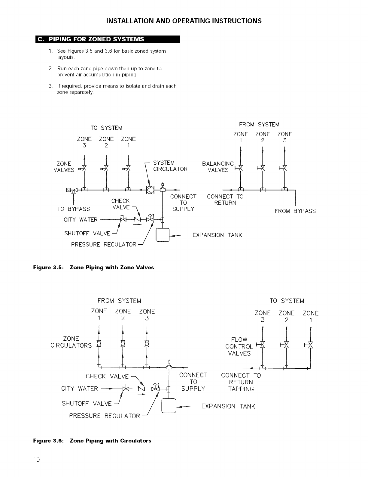
1.
See Figures 3.5 and 3.6 for basic zoned system
layouts.
2.
Run each zone pipe down then up to zone to
prevent air accumulation in piping.
3.
If required, provide means to isolate and drain each
zone separately.
TO SYSTEM
ZONE ZONE
3 2
VALVES
B-_ I CHECK
TO BYPASS VALVE
CITY WATER
SHUTOFF VALVE
PRESSURE REGULATOR
Figure 3.5: Zone Piping with Zone Valves
ZONE
1
SYSTEM
CIRCULATOR
CONNECT
SUPPLY
BALANCING ,
VALVES H, _-
CONNECT TO
TO
EXPANSION TANK
RETURN
FROM SYSTEM
ZONE ZONE ZONE
1 2 5
FROM
BYPASS
FROM SYSTEM
ZONE ZONE ZONE
1 2 5
ZONE
CIRCULATORS
CHECK VALVE
CITY WATER
SHUTOFF VALVE
PRESSURE REGULATOR
Figure 3.6: Zone Piping with Circulators
10
CONNECT
TO
SUPPLY
FLOW
CONTROL
VALVES
CONNECT TO
RETURN
TAPPING
EXPANSION TANK
TO SYSTEM
ZONE ZONE
3 2
!
ZONE
1
t

INSTALLATION AND OPERATING INSTRUCTIONS
1, Consult the tank manufacturer's instructions for
specific information relating to tank installation. Size
the expansion tank for the required system volume
and capacity. See Table 10.2 in Section 10 for boiler
water capacity.
2. Expansion tanks are available with built-in fill valves
and check valves for reducing supply water pressure
and maintaining minimum system pressure. Check
the design features of the tank and provide valves as
necessary.
Refer back to Figure 3.1 for typical expansion tank piping.
:II IhH,] 1:1:(.i ,'li 1:1!,] iviv/.,l/ ! :I I: I:/.,1i ! :1
If the boiler is to be used in conjunction with an indirect-
fired water heater, refer to Figure 3.7 for typical piping.
Follow the instructions provided by the water heater
manufacturer. Pipe the water heater as a separate zone.
II1_1!:I'I ! ".1f(,l i :(,.i i [,] _IOI 1:13".1.'I_q,.'][.] _Ii L'I _H3
For new or existing systems that must be freeze-
protected:
Use only inhibited propylene glycol solutions of up to
50% by volume with water. Ethylene glycol is toxic
and can attack gaskets and seals used in hydronic
systems.
1,
Glycol in hydronic applications is specially
formulated for this purpose. It includes inhibitors
which prevent the glycol from attacking metallic
system components. Make certain that the system
fluid is checked for the correct glycol concentration
and inhibitor level.
2,
The antifreeze solution should be tested at least once
a year and as recommended by the antifreeze
manufacturer.
3,
Antifreeze solutions expand more than water. For
example, a 50% by volume solution expands 4.8%
in volume for a temperature increase from 32°F
(O°C) to 180°F (82°C), while water expands 3% with
the same temperature rise. Allowance must be made
for this expansion in system design.
SYSTEM
CIRCULATOR
SUPPLY TO
SYSTEM
EXPANSION
TANK
RETURN FROM
SYSTEM
HOT DOMES'I'IC
WATER
SUPPLY
COLD
DOMESTIC
WATER SUPPLY
ZONE VALVES
INDIRECT=FIRED
WATER
HEATER
SUPPLY
TO
TANK
BALANCING
VALVE
Figure 3.7: Typical Piping with Indirect-Fired Water Heater
SHUTOFF
VALVE
BALANCING
VALVE:
DRAIN
CHECK
VALVE
SHUTOFF
VALVE
PRESSURE
REGULATOR
COLD
-- WATER
FILL
11
 Loading...