

HydroTherm HV42, HV84, HV120 Installation Instructions Manual
HWFII-4
KICKSPACE HEATER
INSTALLATION INSTRUCTIONS • TYPES HW & HF
RECESSED AND SURFACE MOUNT WALL KITS
RECESSED "HW" / SURFACE MOUNT "HF" WALL KIT
To be used in conjunction with Kickspace Heater • Type HK
Kickspace Heater Installation Instructions
For use with HK42/HK84/HK120 Kickspace Heaters
ATTENTION: READ THESE INSTRUCTIONS CAREFULLY BEFORE ATTEMPTING TO INSTALL, OPERATE, OR
SERVICE THE HYDROTHERM KICKSPACE HEATERS! RETAIN THESE INSTRUCTIONS FOR FUTURE REFERENCE.
INSPECT THE SHIPMENT IMMEDIATELY WHEN RECEIVED TO DETERMINE IF ANY DAMAGE HAS OCCURRED
DURING SHIPMENT.
PRIOR TO INSTALL, CHECK FOR ANY VISIBLE DAMAGE.
GENERAL DESCRIPTION
The Kickspace wall kits have been designed to accommodate a Hydrotherm Kickspace Model HK42, HK84, or HK120
Kickspace heater to deliver a comfortable stream of warmed air through the wall by a unit mounted in the wall, or on the
surface of the wall. Kits consist of front grille panels, back panel, and necessary mounting hardware. The Kickspace heater
is sold separately.
The recessed (HW kits) cabinet for the HW42 will fi t between 16" center studs. The HW84/HW120 will require a small
amount of framing to suit the mounting.
Installation instructions should be read thoroughly IN CONJUNCTION WITH INSTALLATION INSTRUCTIONS AND
WIRING DIAGRAM SUPPLIED WITH KICKSPACE HEATER UNITS, prior to starting installation.
WARNING: DISCONNECT POWER BEFORE SERVICING UNIT,
POTENTIAL ELECTRICAL SHOCK HAZARD!
260 NORTH ELM STREET, WESTFIELD, MASSACHUSETTS 01085
2/12
www.hydrotherm.com
1.
INSTALLATION OF KICKSPACE WALL MODELS - TYPE "HW" AND TYPE "HF"
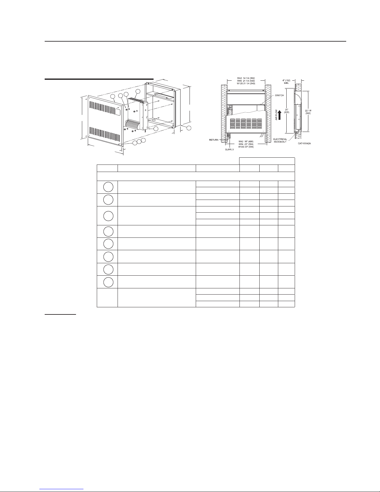
Figures D and F show exploded views of the wall models "HW" & "HF" Kickspace's. Figure E shows the "HW"
type mounted in a wall with an air outlet at the top of the unit. Figure G shows the "HF" type mounted. The
louvers of the front panel will direct the air fl ow as shown. Use the following procedures for installation.
Type HW Installation
3
5
6
1W
25"
(635)
9
8
16" (406) W42
23" (584) W84
23" (584) W120
Figure D Parts List
1W Front Panel Assembly
2W Back Panel Assembly
3 Kickspace Unit (sold separately)
4W Front Panel Mounting Screws J21-00282-003 x x x
5 Lockwashers J24-00322-001 x x x
4W
1/2
(13)
FIGURE D
Description Part No. 42 84 120
7
CAT-55524A
14" (356) W42
21" (533) W84
21" (533) W120
4"
(102)
22 3/32
(561)
2W
BMWR02172-001 x
BMWR02172-002 x x
BMWR02169-001 x
BMWR02169-002 x x
HK42 x
HK84 x
HK120 x
FIGURE E
Model
6 Flanged Nuts J23-00324-001 x x x
7 Kickspace Electrical Box Cover ref item #3 x x x
8/9 Snap Cap / Washers J06-04481 x x x
Figure D
Complete Wall Assembly Type "HW"
(less heater)
TYPE "HW" :
1.) Frame an opening between wall studding as shown in
Figure E. Model HW42 will fi t between studs that are
on 16'' centers. Model HW84 and HW120 will require
a small amount of framing to suit the mounting. A 7/8''
diameter hole is provided at the bottom of the cabinet
interior to provide entrances for electrical connections,
and a 7/8'' diameter knockout is provided at the rear
of the motor in the electrical control box. A 2-1/2''
diameter hole is provided at the bottom of the cabinet
interior to provide an entrance for piping connections.
Cut horizonal framing to clear, as necessary.
2.) After removing the front panel mounting screws (Item
4W), remove the front louvered panel (Item 1W).
Notice the direction of the louvers (see the air fl ow
direction label on inside front label).
3.) Nail the recessed cabinet (Item 2W) to the framed
opening at both sides.
4.) Mount the Kickspace Unit (Item 3) to the recessed
back panel, remove the electrical control box cover
from Kickspace unit. Secure the Kickspace unit in
place using Items 5 & 6 as shown in Figure D. Do
not over tighten.
5.) Remove the heating element from the Kickspace
unit (Item 3) following the procedure described in the
2.
HW42 x
HW84 x
HW120 x
installation of Type "HK". Hold this element and fi ttings
temporarily in place in the recessed cabinet before
soldering to check for clearance and length of tubing
required.
6.) After piping connections have been made, replace
the heating element in the bottom cover in the proper
postition. Place the neoprene side pad in position and
replace the top cover using the 4 screws. Tighten enough
to keep the element in place between the covers. DO
NOT OVER-TIGHTEN!
7.) Electrical connections for the wall units are to be
made as shown in Kickspace Type "HK" Installation
Manual page 3.
8.) Make fi nal piping and electrical connections (see
Kickspace Type "HK" Installation Manual pages 3 &
4) to the system in the cabinet. Secure in place the
Kickspace electrical control box cover. Turn on the
system, purge of air, check blower operation, and
check for any possible leaks in the piping.
9.) Replace front panel (Item 1W), place washers (Items 8)
in required positions, screw through holes and tighten.
10.) Place snap-cap® (Item 9) over washer at angle. Push
snap-cap® (Item 9) DOWN fi rmly until it engages with
a snap.
 Loading...