

HydroTherm HC-65, HC-120, HC-85, HC-145, HC-165 Installation Operation & Maintenance
...
HCD2-501
42-9156 REV. 1
MODEL HC-D SERIES
INSTALLATION,
OPERATION &
MAINTENANCE
MANUAL & REPLACE-
MENT PARTS MANUAL
Gas-Fired Cast Iron Water Boilers
65,000 to 165,000 Btuh Input
Intermittent Pilot & Vent Damper
SECTION 1: BOILER INSTALLATION
Introduction...............................................................2
Step 1: Locating & Setting the Boiler........................3
Step 2: Installing/Purging Water Piping.....................4
Step 3: Venting the Boiler..........................................6
Step 4: Installing/Testing Gas Piping ........................8
Step 5: Wiring the Boiler...........................................9
SECTION 2: START-UP & OPERATION
Safety Controls........................................................15
Start-Up & Adjustments...........................................15
HYDROTHERM
SECTION 3: MAINTENANCE
Water Treatment......................................................18
Freeze Protection....................................................18
Before Each Heating Season..................................18
How To Change Orifices..........................................19
Troubleshooting.......................................................19
Appendix A (French Vent Damper Translation)....... 20
Replacement Parts List......................................... 21
MEA# 90-77-E
IN UNITED STATES: 260 NORTH ELM ST., WESTFIELD, MA 01085 (413) 564-5515/FAX (413) 568-9613
IN CANADA: 5211 CREEKBANK ROAD, MISSISSAUGA, ONT. L4W 1R3 (905) 625-2991/FAX (905) 625-6610

ANSI/ASME CODE COMPLIANCE: Installation must
conform to requirements of authority having jurisdiction
or, in absence of such requirements, to National Fuel
Gas Code ANSI Z223.1-latest edition and to National
Electric Code NFPA-70-latest edition. Where required by
authority having jurisdiction, installation must also conform to Standard for Controls and Safety Devices for
Automatically Fired Boilers, ANSI/ASME CSD-1-latest
edition.
Part 2, and/or local codes.
BOILER SHIPMENT: Each boiler is shipped in a single
carton. There is a vent damper packed separately with
the boiler.
WARNING: Installers must follow local regulations
with respect to the installation of CO detectors and
follow the manufacturer's stated maintenance
schedule for this boiler!
For Canada, the installation must be in accordance with
Standards CAN/CGA-B149.1 or .2 Installation Codes for
Gas Burning Appliances and Equipment and with Standard C.S.A. C22.1 Canadian Electrical Code, Par t 1 and
E
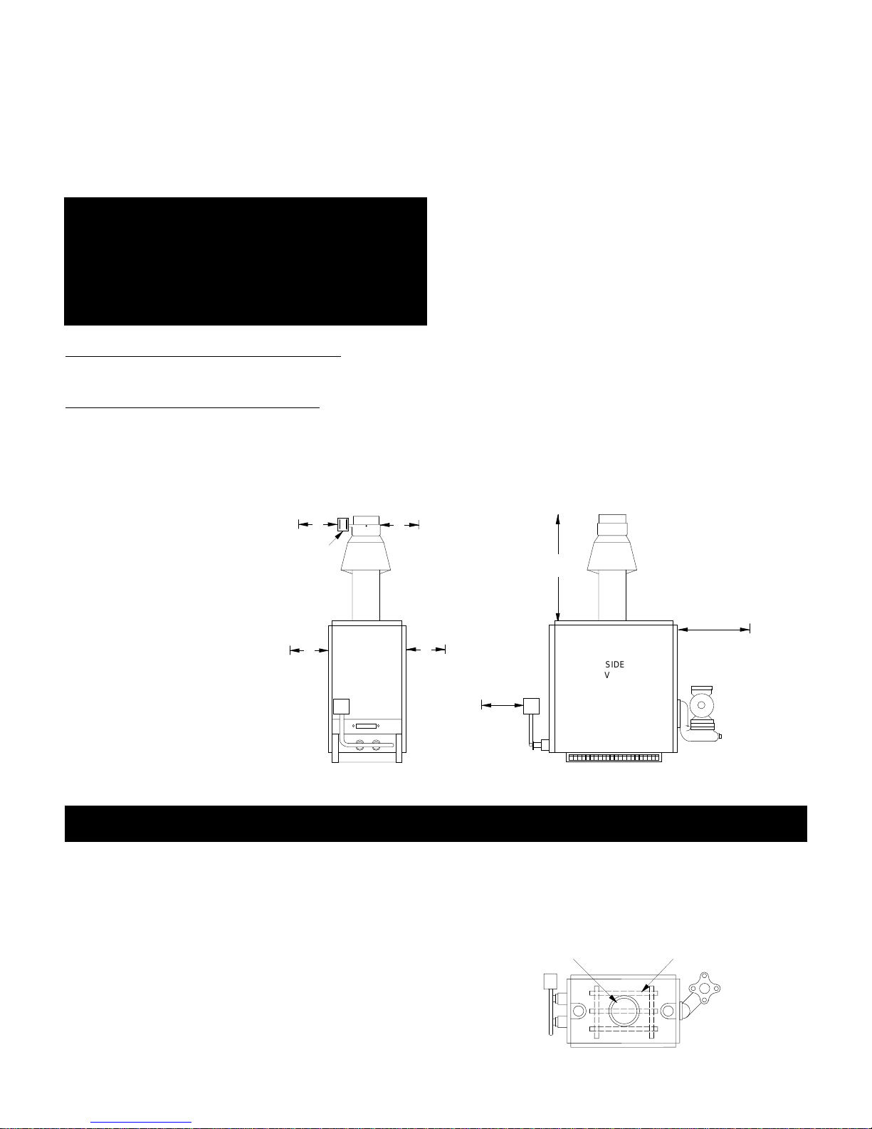
3 5/8"
C
SPILL
SWITCH
D
A
A
BOILER
MODEL
HC-65
HC-85
HC-100
HC-120
HC-145
HC-165
HI-LIMIT AQUASTAT
A
19 1/2"
23 3/4"
23 3/4"
23 3/4"
27 1/4"
29"
DIMENSIONS
B
12 3/4"
12 3/4"
12 3/4"
12 3/4"
12 3/4"
16"
GAS VALVE
C
16 1/2"
16 1/2"
16 1/2"
30 1/2"
33- /4"
32 1/2"
1 1/2" SUPPLY
HC-85, 100,120
ATTENTION: Observer les règlements règional à
l'egard des détecteurs de monoxyde de carbone et
observer entretien de manufacturier pour cette
chaudière!
D
39 5/8"
43 7/8"
43 7/8"
57 7/8"
64 1/8"
65 1/8"
E
5"
5"
5"
6"
6"
7"
1 1/2" SUPPLY
HC-65, 145, 165
PRESS./RELIEF VALVE
HC-65, 145, 165
VENT DAMPER
PRESS./RELIEF VALVE
HC-85, 100, 120
AIR ELIMINATOR
TAPPING
EXPANSION TANK
TAPPING
1 1/4"
RETURN
CIRCULATOR
(PACKAGED
BOILERS)
TEMP./PRESS. INDICATOR
ROLLOUT SWITCH
B
5 1/2"
21 3/4" 7 3/4"
MODEL HC-D BOILER DIMENSIONS
The following terms are used throughout this manual to bring attention to the presence of potential hazards
or to important information concerning the product:
DANGER: Indicates an imminently hazardous situation which, if not avoided, will result in death,
serious injury or substantial property damage.
WARNING: Indicates a imminently hazardous situation which, if not avoided, could result in
death, serious injury or substantial property damage.
CAUTION: Indicates a imminently hazardous situation which, if not avoided, may result in minor
injury or property damage.
NOTE: Used to notify of special instructions on
installation, operation or maintenance which are
important to equipment but not related to personal
injury hazards.
DRAIN
VALVE
2
SECTION 1: BOILER INSTALLATION
STEP 1: LOCATING & SETTING THE BOILER
PROCEDURE A: Check that provisions for combustion air are in accordance with National Fuel Gas Code
ANSI Z223.1-latest edition and all applicable local codes.
In Canada, follow CAN/CGA B149.1 or .2 installation codes.
WARNING: This boiler must be supplied with combustion air in accordance with Section 5.3, Air for
Combustion & Ventilation, of the latest revision of
the National Fuel Gas Code, ANSI Z223.1 and all
applicable local building codes. Failure to provide
adequate combustion air for this appliance can result
in severe personal injury or death!
If boiler is installed in an unconfined space, adequate air
will be available via normal infiltration.
If boiler is installed in a confined space
(a space with a
volume of less than 50 cubic feet per 1000 Btu/hr of gas
input for all fuel burning equipment) or building construction is unusually tight, adequate air for combustion must
PROCEDURE B: Check minimum clearances to combustibles are proper as
shown. Local requirements
may specify greater clear-
6"
VENT
DAMPER
6"
ances & must be adhered to.
Boiler shall be installed such
that the gas ignition system
components are protected
from water (dripping, spraying, rain, etc.) during appliance operation and service
(circulator replacement, con-
LEFT
6"
FRONT
VIEW
RIGHT
RECOMMEND
MORE FOR
ACCESS TO
VENT DAMPER
POSITION
INDICATOR
densate trap, control replacement, etc.).
be provided by two openings: one located about 6" below
the ceiling, the other about 6" above the floor. When
communicating directly with the outside, each opening
must have a minimum free area of one square inch per
4000 Btu/hr of gas input. When ventilation air is provided
by openings in doors, etc. to adjoining spaces having
adequate infiltration, each opening must have a minimum
free area of one square inch per 1000 Btu/hr of gas
input.
NOTE: Boiler employs atmospheric combustion.
Combustion air must not be contaminated with halogenated hydrocarbon vapors, aerosol propellants or
freon; otherwise, heat exchanger will be subject to
corrosion, reducing boiler life.
FIGURE 1.1
TOP
48"
REAR
(6")
W/O CIRC.
6"
FRONT
CLOSET
(6")
SIDE
VIEW
24" WITH
CIRCULATOR
(RECOMMENDED
FOR SERVICING)
WARNING: Never install boiler on combustible flooring without combustible flooring pan or on carpeting as
heat damage and/or fire may result.
NOTE: Do not loosen tie rods on absorption unit. They accommodate thermal expansion. Loss of boiler
structural integrity and water leaks/damage may result.
CAUTION: Locate boiler so horizontal connecting flue pipe is as short as possible. Maximize height of vertical flue connector.
PROCEDURE C: Check component positioning.
1. Remove all packing material from boiler.
2. Check that burners and controls are in the proper
position.
3. Check proper seating of baffle grid inside of dome
opening (see Figure 1.2)
.
DOME
TOP VIEW
BAFFLE GRID
FIGURE 1.2
3
STEP 2: INSTALLING & PURGING WATER PIPING
NOTE: Boiler must not be used without forced circulation, as overheating or failure of cast iron sections may
result.
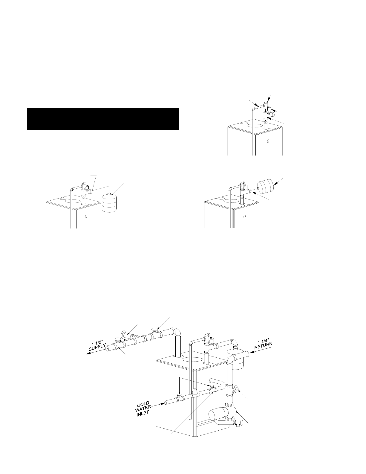
PROCEDURE A: Install vent tapping assembly, components and relief valve discharge piping. For Models
HC-65, 145 & 165, supply outlet is at rear of boiler and vent fitting assembly tapping is at front of boiler.
Relief Valve Discharge Piping: Must terminate 6"
above floor & be same size or larger than valve outlet.
WARNING: No valve of any type may be installed
between boiler & relief valve to prevent accidental
explosion from over-pressure.
CAUTION: Piping must be installed from relief valve
discharge so there will be no danger of scalding personnel.
1/2" NPT TAPPING
VERTICAL EXPANSION TANK
ARRANGEMENT (PREFERRED)
MAY BE PIPED TO
EITHER SIDE OF BOILER
RELIEF VALVE
DISCHARGE
PIPING
PRESS. RELIEF
VALVE
AIR VENT
VENT
FITTING
ASS'Y.
HORIZONTAL EXPANSION
TANK ARRANGEMENT
MAY BE SCREWED
INTO TAPPING
FIGURE 1.3
PROCEDURE B: Install supply and return water piping. For Models HC-65, 145 & 165, supply outlet is
at rear of boiler and vent fitting assembly tapping is
at front of boiler.
SHUT-OFF VALVE
DRAIN VALVE
SHUT-OFF
VALVE
SHUT-OFF
VALVES
If boiler is installed above level of radiation, a low
water cut-off must be used.
ALL EXTERNAL PIPING MUST BE SUPPORTED BY
HANGERS, NOT BY BOILER OR ACCESSORIES.
SHUT-OFF
VALVE
CIRCULATOR
PRESS. REDUCING
(FILL) VALVE
FIGURE 1.4
4
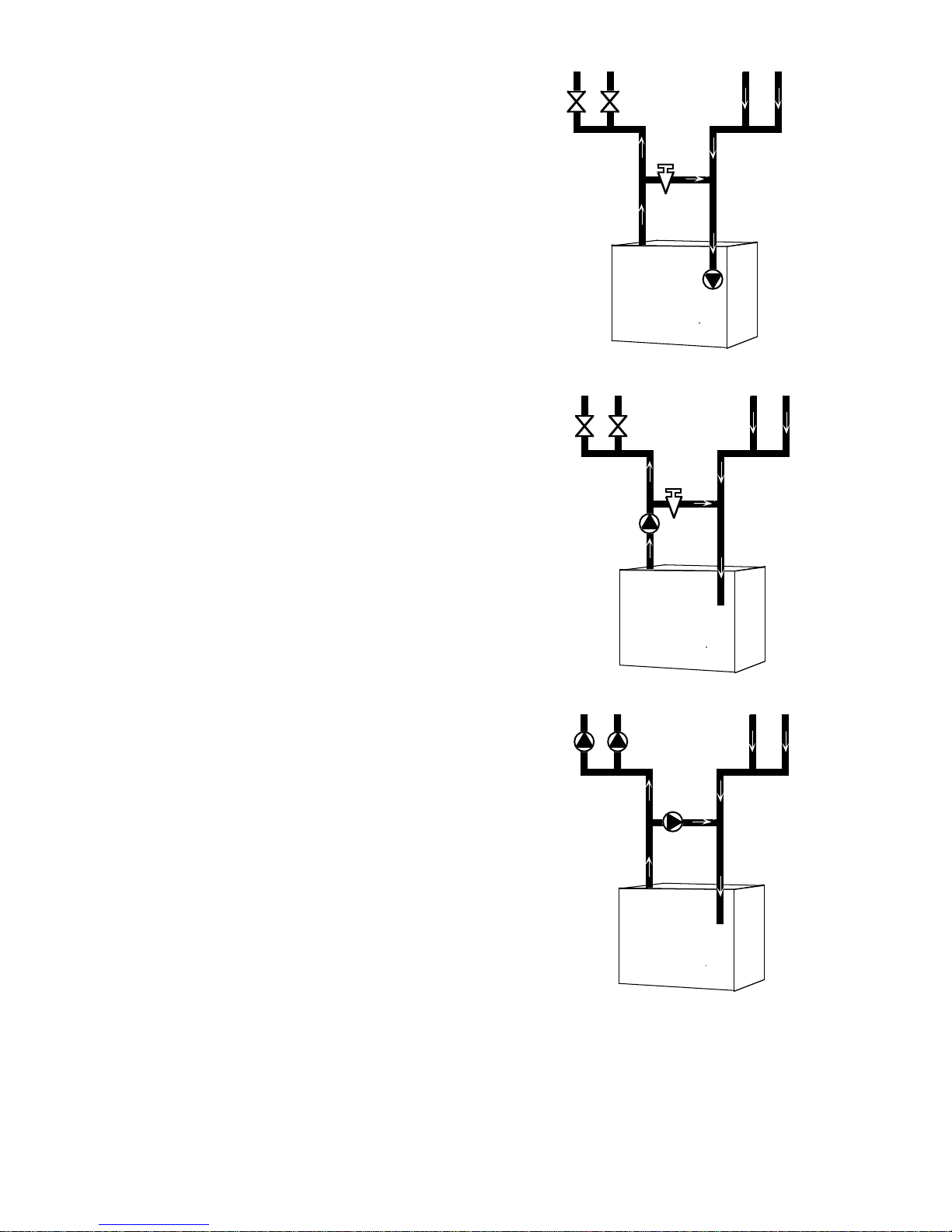
CAUTION: To prevent damage due to excessive condensation, one of the following piping options
should be used.
SUPPLY
RETURN
SYSTEM BYPASS
For systems using a circulator on the return as either a single zone, or multiple zones with zone valves, install a system bypass line between the supply and return on the suction side of the circulator (see Figure 1.5). Install a metering
valve in this bypass line to regulate the amount of flow that
will be diverted to the return. A plug valve offers the best
control for this application. Although other valves may be
less expensive , a plug v alv e will be easier to set accurately.
In the absence of a flow indicator, set the metering valve
using temperature as a guide. The accompanying diagram suggests one scenario. This addition requires only
two tees, a plug valve, and a small amount of pipe and
offers the simplest approach to reliably control condensation. For this system and those that follow, be aware that
you are using a percentage of the pump capacity to
blend, but the friction loss for the entire pump flow has
been reduced. In most cases, the standard pump packaged with the boiler has enough capacity to feed the
baseboard distribution system and the bypass line.
PUMP AWAY BYPASS
For systems that use a single circulator to pump away
from the boiler, the bypass should be installed on the discharge side of the circulator (see Figure 1.6). Full temperature water supplies the baseboard distribution system as before. Half of the circulator’s volume moves
through the bypass, blending and heating the cooler
return water. Again, the cost of installing the bypass is
small and setting it by temperature can be accomplished
with a contact thermometer.
PUMPED BLEND
An additional circulator can also be used to provide a
return water temperature blend. This method works well
with systems with multiple zones with circulators (see
Figure 1.7). The dedicated bypass circulator provides a
strong blending flow without diminishing the flow available to any heating zone. Any residentially sized circulator is adequate for this purpose.
50%
160° F
100%
160° F
50%
160° F
100%
160° F
100%
160° F
200%
160° F
50%
160° F
SYSTEM
BYPASS
SUPPLY
50%
160° F
RETURN
PUMP AWAY
BYPASS
SUPPLY
100%
160° F
RETURN
50%
120° F
100%
140° F
50%
120° F
100%
140° F
100%
120° F
200%
140° F
FIGURE 1.5
FIGURE 1.6
Each of these bypass solutions also has the added benefit of increasing circulation in the boiler which will maximize tankless coil output and increase the accuracy of
temperature sensing controls.
REVERSE ACTING AQUASTATS
An alternative for existing systems experiencing condensation that does not require re-piping the boiler utilizes a
reverse acting aquastat, one that makes on temperature
rise. This approach works best in single zone systems.
Wired in series with the circulator, this control holds the circulator off until the boiler reaches an acceptable temperature and then starts system circulation (see Figure 1.8).
PUMPED
BYPASS
FIGURE 1.7
5
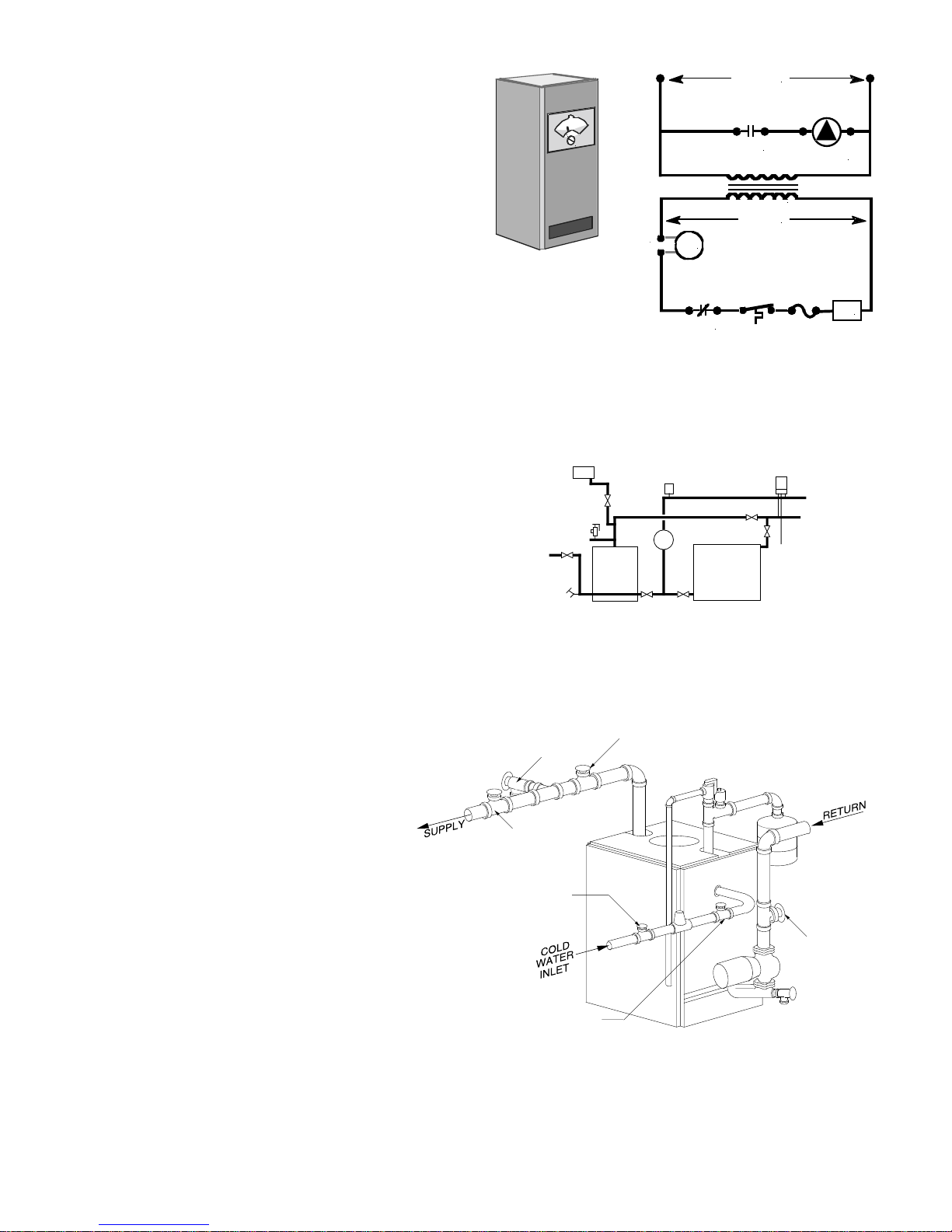
The most commonly available reverse acting aquastat is
a Honeywell L4006B. The aquastat should be mounted
in an immersion well directly installed in the boiler. The
use of heat conductive grease (Honeywell part #
972545) in the immersion well is strongly recommended
for fast and accurate temperature response. Set this
adjustable aquastat to make at no less than 130° F.
While this method can cause the circulator to cycle more
frequently, setting the aquastat’s differential to the maximum (25-30°F) will minimize short cycling.
115 volts
reverse
aquastat
N.O.
24 volts
T
t'stat
T
circulator
REVERSE
AQUASTAT
SET AT 120° F
PROCEDURE C: For combination heating and cooling installations only.
If a hot water boiler is installed in connection with a water
chiller, the chilled water must be piped in parallel with the
boiler, using appropriate valves to prevent the chilled
medium from entering the boiler (see Figure 1.9). When
boilers are connected to heating coils located in air handling units where they may be exposed to refrigerated air
circulation, such boiler piping system shall be equipped
with flow-control valves or other automatic means to prevent gravity circulation of the boiler water during the cooling cycle.
PROCEDURE D: Completely fill & purge
heating system. Make sure that all heating system manual air vents are closed.
DRAIN
VALVE “B”
NOTE: VALVES "H" OPENED ON HEATING WITH "C" VALVES
CLOSED REVERSE PROCEDURE ON COOLING.
RELIEF
VALVE
FILL
VALVE
EXP. TANK
BOILER
BOILER
VALVE “A”
operating
aquastat
N.C.
VENT
PUMP
H
C
CHILLER
ROOM
UNIT
H
C
DRAIN
GV
FIGURE 1.8
FIGURE 1.9
1. Check flow direction arrows on hydronic
components are facing in proper direction.
2. Attach hose to drain valve "B" and close
valve "A". Open valves "C", "D", "E" and "F"
and drain valve "B". Fill system with water
until water runs out of the hose in a steady
stream (no visible air bubbles).
3. Close valves "C" and "D". Open valve "A".
When water runs out of the hose in a steady
stream (no visible air bubbles), close drain
valve "B".
4. Open valves "C" and "D".
FOR WATER TREATMENT & FREEZE PROTECTION REQUIREMENTS,
SEE "SECTION 3: MAINTENANCE" IN THIS MANUAL
VALVE “C”
VALVE “E”
VALVE “D”
VALVE “F”
FIGURE 1.10
6
STEP 3: VENTING THE BOILER
DANGER: Draft hood and vent outlet must not be altered, as proper operation would be jeopardized;
flame rollout, fire or carbon monoxide poisoning will result.
NOTES: Additional venting and chimney requirements are provided on page 8.
For boilers equipped with intermittent pilot install plug supplied in damper
package into damper vane hole. For standing pilot boilers discard plug.
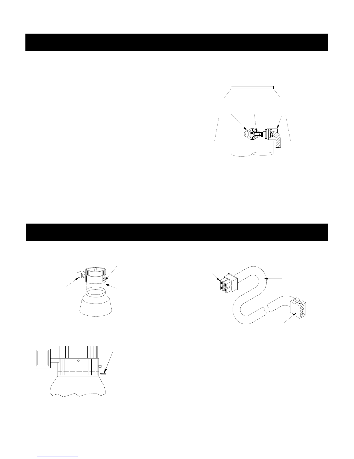
PROCEDURE A: Mount draft hood and spill switch
on boiler.
1. Install draft hood on boiler. If draft hood shroud has a
hole near the relief opening, mount draft hood so hole
faces to the front of the boiler.
2. HC-D boilers are equipped with factory-mounted spill
switch harness/mounting bracket assembly; spill switch is
provided in bag on boiler front.
3. Install mounting bracket on outside surface of draft
hood shroud with the screws provided (HARNESS
MUST BE ON OUTSIDE OF SHROUD). Install spill
switch in hole in shroud (on outside surface) with the
screws provided.
INSTALL
SWITCH
IN OPENING
ON DRAFTHOOD
CONNECT
WIRE
LEADS
4. Plug wiring leads from harness/bracket assembly onto
flat terminals on spill switch.
NOTE: Boiler will not operate unless wiring leads to
spill switch are connected.
INSTALL
MOUNTING
BRACKET
ON DRAFTHOOD
FIGURE 1.11
PROCEDURE B: Install vent damper. (For French version, see Appendix A at rear of manual.)
DANGER: Only the boiler may be served by the vent damper. Do not use it to vent an additional appliance;
this will cause fire or carbon monoxide poisoning.
1. Mount damper on top of draft hood.
FLOW DIRECTION
ARROW POINTS UP
MAKE SURE
MOTOR IS
LOCATED
ON LEFT SIDE
MOUNT
VENT DAMPER
OVER
DRAFTHOOD
FIGURE 1.12
2. Secure damper to draft hood.
ATTACH LOWER
PORTION OF
VENT DAMPER
TO DRAFTHOOD
WITH 1/2" OR
SHORTER SCREWS
OR POP RIVETS
PLUG INTO MOLEX
RECEPTACLE INSIDE
DAMPER MOTOR
3. Connect wire harness.
VENT
DAMPER
WIRE
HARNESS
PLUG INTO MOLEX
RECEPTACLE ON FRONT
OF BOILER
FIGURE 1.14
FIGURE 1.13
7
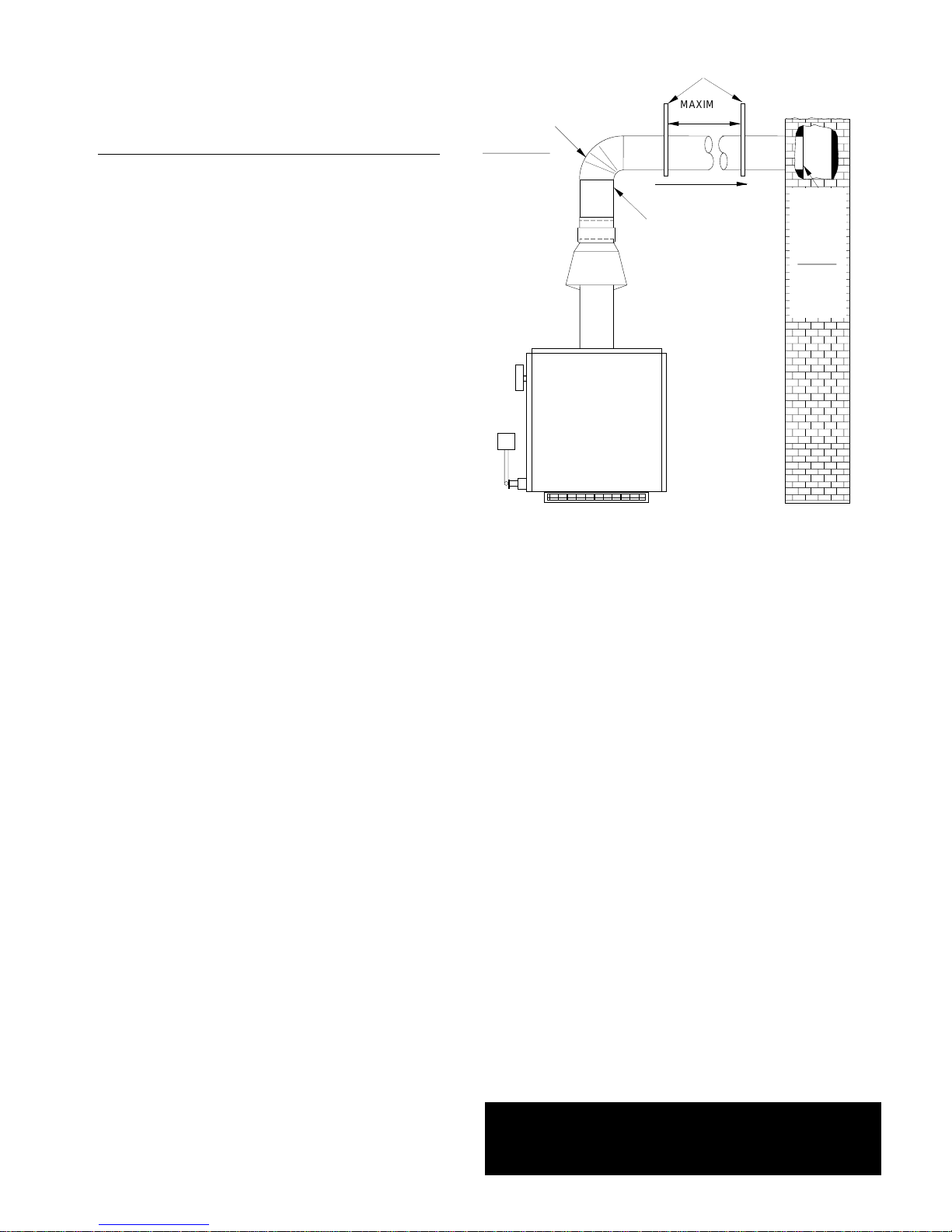
PROCEDURE C: Install flue pipe between vent
damper and chimney (6" minimum clearance
required between flue pipe and combustibles).
ADDITIONAL VENTING REQUIREMENTS: When con-
necting to gas vents or chimneys, vent installations shall
be in accordance with Part 7, Venting of Equipment, of
the National Fuel Gas Code, ANSI Z223.1-latest edition,
or applicable provisions of the local building codes.
Vent connectors serving appliances vented by natural
draft shall not be connected into any portion of mechanical draft systems operating under positive pressure.
When two or more appliances vent into a common flue,
the area of the common flue should be at least equal to
the area of the largest flue plus 50% of the areas of the
additional flue or vent connectors.
SINGLE WALL
OR TYPE B
FLUE PIPE
HC-65 = 5"
HC-85 = 5"
HC-100 = 5"
HC-120 = 6"
HC-145 = 6"
HC-165 = 7"
USE VENT SUPPORT(S) AS REQUIRED TO PREVENT SAGGING
MAXIMUM
6-FT
APART
PITCH 1/4"
PER FOOT
SECURE
FLUE PIPE
TO VENT
DAMPER
INSTALL
FLUSH
WITH
INSIDE
CHIMNEY
LINER
SEAL
WITH
FURNACE
CEMENT
FIGURE 1.15
When an existing boiler is removed from a common venting system, common venting system is likely to be too
large for proper venting of appliances remaining connected to it. At time of removal of existing boiler, following
steps shall be followed with each appliance remaining
connected to the common venting system placed in operation, while other appliances remaining connected to
common venting system are not in operation:
1. Seal all unused openings in common venting system.
2. Visually inspect the venting system for proper size and
horizontal pitch and determine there is no blockage or
restriction, leakage, corrosion and other deficiencies
which could cause an unsafe condition.
3. Insofar as is practical, close all building doors and windows and all doors between the space in which the appliances remaining connected to the common venting system are located and other spaces of the building. Tur n on
clothes dryers and any appliance not connected to the
common venting system. Tur n on any exhaust fans, such
as range hoods and bathroom exhausts, so they will
operate at maximum speed. Do not operate a summer
exhaust fan. Close fireplace dampers.
4. Place in operation the appliance being in-spected. Follow the lighting instructions. Adjust thermostat so appliance will operate continuously.
6. After it has been determined that each ap-pliance
remaining connected to common venting system properly
vents when tested as outlined above, return doors, windows, exhaust fans, fireplace dampers and any other
gas-burning appliance to previous conditions of use.
7. Any improper operation of the common venting system
should be corrected so installation conforms with the
National Fuel Gas Code, ANSI Z223.1-latest edition.
When resizing any portion of the common venting system, the common venting system should be resized to
approach the minimum size as determined using the
appropriate tables in Appendix G in the National Fuel
Gas Code, ANSI Z223.1-latest edition. For Canada, the
provisions of CAN/CGA B149.1 or .2 shall apply.
ADDITIONAL CHIMNEY REQUIREMENTS: Chimney
condition is of paramount importance for a safe and efficient boiler installation. All installations must include a
chimney inspection by a qualified individual or agency.
Chimney construction materials must be compatible with
the fuel being used.
Particular attention should be paid on all oil-to-gas conversions.Soot may have accumulated in chimney and/or
degraded chimney liner. Most utilities require complete
chimney cleaning. Others may require installation of new
liner, spill switches or other chimney upgrades. Check
with local utility for required safety precautions.
5. Test for spillage at draft hood relief opening after 5
minutes of main burner operation. Use the flame of a
match or candle, or smoke from cigarette, cigar or pipe.
DANGER: A chimney which does not meet modern
safety standards will result in a fire or deadly carbon
monoxide poisoning of the building residents.
8
 Loading...