

Page 1
MODEL FX SERIES
INSTALLATION, OPERATION
AND MAINTENANCE MANUAL
Direct Vent, Natural or Propane
Gas-Fired Cast Iron Water Boilers
70,000 to 210,000 Btuh Input
FXIOM-1
WARNING: If the information in this manual is not followed exactly, a fire
or explosion may result causing property damage, personal injury or loss of life.
Do not store or use gasoline or other flammable vapors and liquids in the vicinity of
this or any other appliance.
WHAT TO DO IF YOU SMELL GAS:
• Do not try to light any appliance.
• Do not touch any electrical switch. Do not use any phone in your building.
• Immediately call your gas supplier from a neighbor’s phone. Follow the gas
supplier’s instructions.
• If you cannot reach your gas supplier, call the fire department.
Installation and service must be performed by a qualified installer, service agency or
the gas supplier.
INSTALLER, THESE INSTRUCTIONS TO BE AFFIXED ADJACENT TO THE HEATER.
CONSUMER, RETAIN THESE INSTRUCTIONS FOR FUTURE REFERENCE PURPOSES.
IN UNITED STATES: 260 NORTH ELM ST. • WESTFIELD, MA 01085 • (413) 564-5515 • FAX (413) 568-9613
IN CANADA: 5211 CREEKBANK RD. • MISSISSAUGA, ONT. L4W 1R3 • (905) 625-2991 • FAX (905) 625-6610
www.hydrotherm.com
Page 2

Page 2 FX DIRECT VENT BOILER INSTALLATION AND OPERATION INSTRUCTIONS
AVERTISSMENT. Assurez-vous de bien suivre les instructions données dans cette
notice pour réduire au minimum le risque d’incendie ou d’explosion ou pour éviter
tout dommoge matériel, toute blessure ou la mort
Ne pas entreposer ni utiliser d’essence ou ni d’autres vapeurs ou liquides inflammables
à proximité de cet appareil ou de tout autre appareil.
QUE FAIRE SI VOUS SENTEZ UNE ODEUR DE GAZ:
• Ne pas tenter d’allumer d’appareil.
• Ne touchez à aucun interrupteur; ne pas vous servir des téléphones se trouvant dans
le bâtiment.
• Appelez immédiatement votre fournisseur de gas depuis un voisin. Suivez les
intructions du fournisseur.
• Si vous ne purvez rejoindre le fournisseur, appelez le service des incendies.
L’installation et l’entretien doivent être assurés par un installateur ou un service
d’entretien qualifié ou par le fournisseur de gaz.
CONTENTS
Before You Start .................................................page 2
Boiler Ratings & Capacities................................page 3
Boiler Location ...................................................page 3
Clearances to Combustible Construction...........page 3
Combustion Air & Ventilation..............................page 4
Chimney & Vent Pipe Connections ..................page 10
Heating System Piping.....................................page 15
Gas Supply Piping............................................page 18
Electrical Wiring ...............................................page 18
Lighting Instructions .........................................page 22
Boiler Set Up ....................................................page 24
Boiler Operation ...............................................page 24
Checking & Adjusting .......................................page 25
Boiler Maintenance ..........................................page 26
Replacement Parts...........................................page 28
Instructions to the Installer ...............................page 31
Health Warnings...............................................page 31
BEFORE YOU START
WARNING: This manual must be read and fully
understood before installing, operation or
servicing this boiler! Failure to follow these
instructions could result in a fire or explosion
causing extensive property damage, personal
injury or death!
Each unit has been constructed and hydrostatically
tested for a maximum working pressure of 30 psi in
accordance with the ASME Boiler and Pressure Vessel
Code, Section IV for cast iron boilers. Each boiler has
been equipped with a 30 psi pressure relief valve.
This manual covers the application, installation, operation
and maintenance of a FX low pressure hot water boiler .
To obtain the safe, dependable, efficient operation and
long life for which this boiler was designed, these
instructions must be read, understood and followed.
Direct all questions to your Hydrotherm distributor or to
the Customer Service Department, 260 North Elm
Street, Westfield, MA 01085. Always include the model
and serial numbers from the rating plate of the boiler in
question.
The owner should maintain a record of all service work
performed with the date and a description of the work
done. Include the name of the ser vice organization for
future reference.
Where required by the authority having jurisdiction, the
installation must conform to the Standard for Controls
and Safety Devices for Automatically Fired Boilers,
ANSI/ASME CSD-1.
These instructions cover the FX gas fired, direct vent,
low pressure, sectional, cast iron hot water boiler. FX
boilers have been design certified by CSA for use with
natural and propane gas under the latest edition of
ANSI-Z21.13/CSA 4.9, Gas-Fired Low Pressure Steam
and Hot Water Boilers.
The installation must conform to the requirements of the
authority having jurisdiction or, in the absence of such
requirements, to the National Fuel Gas Code, ANSI
Z223.1-latest revision. In Canada, the installation must
be in accordance with the requirements of CSA B149.1
or B149.2 Installation Code for Gas Burning Appliances
and Equipment.
Page 3
FX DIRECT VENT BOILER INSTALLATION AND OPERATION INSTRUCTIONS Page 3
BOILER RATINGS & CAPACITIES
Before undertaking the installation of the FX check the
boiler rating plate to ensure that the boiler is the proper
size for the job. The "Net I=B=R Ratings" specify the
equivalent amount of direct cast iron radiation that the
boiler can handle under normal conditions.
Also ensure that the boiler has been set up for the type
of gas available at the installation site. Other important
considerations are the availability of an adequate
electrical supply, fresh air for combustion and proximity
a suitable outside wall.
BOILER LOCATION
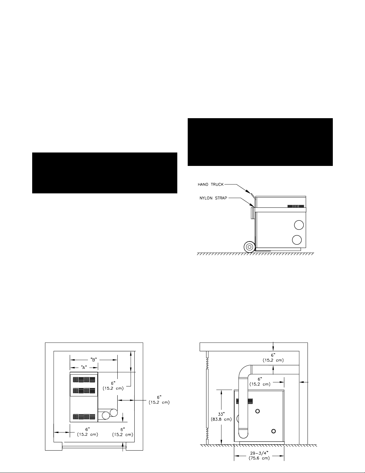
WARNING: The clearances to combustible
construction show in Figure 1 must be maintained. Failure to comply with this warning can
result in extensive property damage, severe
personal injury or death!
CAUTION: Do not lift the boiler by the jacket. Use a
hand truck under the base frame as shown in Figure 2.
NOTE: This boiler is designed for direct placement
on a combustible floor. Never install this boiler on
carpeting!
4. DO NOT install this boiler in a location that would
subject any of the gas ignition components to direct
contact with water or excessive moisture during
operation or servicing.
5. NEVER store objects on or around the boiler.
WARNING: Never store combustible materials,
gasoline or any product containing flammable
vapors or liquids in the vicinity of the boiler.
Failure to comply with this warning can result
in extensive property damage, severe personal
injury or death!
Figure 2 - Moving Boiler
1. Locate the boiler in an area that provides good
access to the unit. Keep in mind that servicing may
require the removal of jacket panels. Accessibility
clearances must take precedence over fire
protection clearances.
2. An optimum site will be level, central to the hot water
piping system, close to an outside wall and have
adequate fresh air for combustion.
3. Ensure that the floor is structurally sound and will
support the weight of the boiler.
Figure 1 - Clearances to Combustible Construction
Page 4

Page 4 FX DIRECT VENT BOILER INSTALLATION AND OPERATION INSTRUCTIONS
COMBUSTION AIR & VENTILATION
WARNING: This boiler must be supplied with
combustion air in accordance with Section 5.3,
Air for Combustion & Ventilation, of the latest
revision of the National Fuel Gas Code, ANSI
Z223.1/NFPA 54 and all applicable local building
codes. Canadian installations must comply with
CSA B149.1 or .2 Installation Code for Gas
Burning Appliances and Equipment, or
applicable provisions of the local building
codes. Failure to provide adequate combustion
air for this boiler/water heater can result in
excessive levels of carbon monoxide whic h can
result in severe personal injury or death!
To operate properly and safely this boiler requires a
continuous supply of air for combustion. NEVER store
objects on or around the boiler!
CAUTION: Combustion air contaminated with
fluorocarbons or other halogenated compounds
such as cleaning solvents and refrigerants will
result in the formation of acids in the combustion
chamber. These acids will cause premature failure
of the boiler voiding the warranty!
CAUTION: If the boiler is operated while the building
is under construction it MUST be protected from
wood, concrete, sheet rock and other types of dust.
Failure to properly protect the unit from
construction dust will damage the unit voiding the
warranty!
Buildings may require the installation of a fresh air duct
or other means of providing make-up air if the intake
air option isn't used. Any building utilizing other gas
burning appliances, a fireplace, wood stove or any type
of exhaust fan must be checked for adequate
combustion air when all of these devices are in
operation at one time. Sizing of an outside air duct must
be done to meet the requirements of all such devices.
WARNING: Never operate this boiler in an
environment subjected to a negative pressure
unless the air intake is connected to the
outdoors. Failure to comply with this warning
can result in excessive levels of carbon
monoxide causing severe personal injury or
death!
All Combustion Air From Inside The Building
Older houses often have enough “leakage” to provide
an adequate amount of combustion air provided that the
demand for combustion air is not too great, Figure 3.
Homes that are relatively new or “tight” will most likely
require that the combustion be ducted to the boiler from
outside the building. Any home utilizing other gas
burning appliances, a fireplace, wood stove or any type
of exhaust fan must be checked for adequate
combustion air when all of these devices are in
operation at one time.
If the boiler is to be located in an alcove, closet or other
confined space the distances from the boiler and it's
vent system to all-combustible construction must be
equal to or greater than the minimum clearances in
Figure 1. When installed in a closet or confined space
two permanent openings of equal area adjoining another
room or rooms having sufficient volume to meet the
requirements of an unconfined space must be provided,
Figures 4 & 5. Each opening m ust have a minimum free
area of one square inch per 1000 Btu/hr (2200 mm2/
kW) based on the total input rating of all gas utilization
equipment in the confined area. Each opening must be
no less than 100 square inches 64516 mm2) in size. The
upper opening must be within 12 inches (305 mm) of,
but not less than 3 inches (76 mm) from, the top of the
enclosure. The bottom opening must be within 12 inches
(305 mm) of, but not less than 3 inches (76 mm) from,
the bottom of the enclosure.
All Combustion Air From Outside The Building
When installed in a confined space without the intake
air option two permanent openings communicating
directly with, or by ducts to, the outdoors or spaces that
freely communicate with the outdoors must be present.
The upper opening must be within 12 inches (305 mm)
of, but not less than 3 inches (76 mm) from, the top of
the enclosure. The bottom opening must be within 12
inches 305 mm) of, but not less than 3 inches (76 mm)
from, the bottom of the enclosure.
Where directly communicating with the outdoors or
communicating with the outdoors through vertical ducts,
each opening shall have a minimum free area of 1 in2/
4000 Btu/hr (550 mm2/kW) of the total input rating of
all of the equipment in the enclosure.
Where communicating with the outdoors through horizontal ducts, each opening shall have a minimum free
area of 1 in2/2000 Btu/hr (1100 mm2/kW) of the total
input rating of all of the equipment in the enclosure.
When ducts are used, they must have the same crosssectional area as the free area of the opening to which
they connect. Sizing of an outside air duct must be
based on the total input rating of all gas utilization
equipment in the confined space.
Page 5
FX DIRECT VENT BOILER INSTALLATION AND OPERATION INSTRUCTIONS Page 5
When calculating the free area necessary to meet the
make-up air requirements of the enclosure,
consideration must be given to the blockage effects of
louvers, grills and screens.
Screens must have a minimum mesh size of 1/4"
(6.4mm). If the free area through a louver or grill is not
known ducts should be sized per Table 1.
Table 1 - Combustion Air Duct Sizing
Input Btuh
FreshAir
Duct Size
3” x 12”
8” x 8”
8” x 12”
8-1/2” x 16”
1/4” Wire
Screen Mesh
144,000
256,000
384,000
512,000
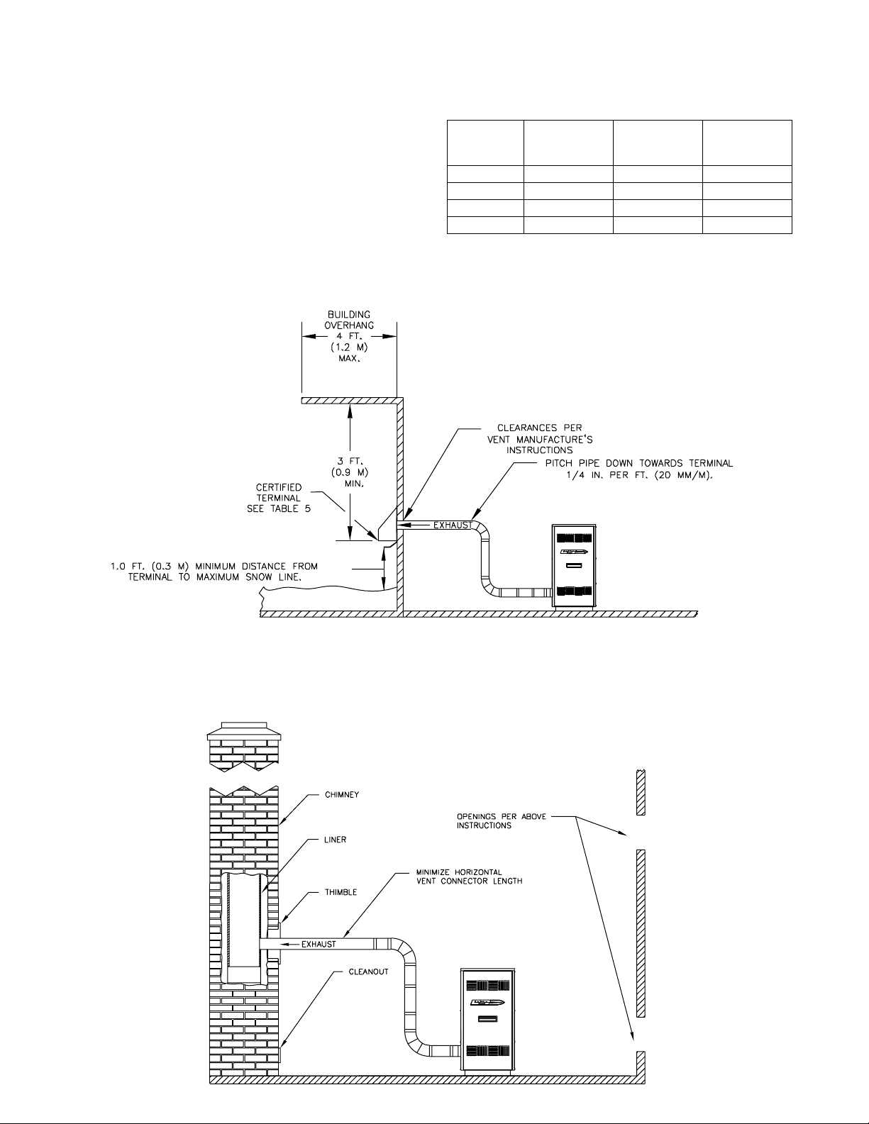
Figure 3 - Horizontal Positive Pressure Venting Using Inside Combustion Air
Input Btuh
Metal
Louvers
108,000
192,000
288,000
384,000
Input Btuh
Wooden
Louvers
36,000
64,000
96,000
128,000
Figure 4 - Vertical Negative Pressure Masonry Chimney System Using Inside Combustion Air
Page 6
Page 6 FX DIRECT VENT BOILER INSTALLATION AND OPERATION INSTRUCTIONS
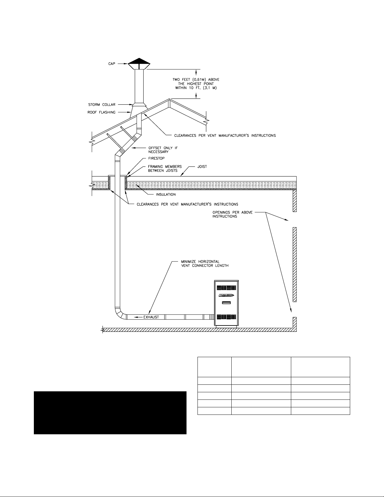
Figure 5 - Vertical Negative Pressure Metal Chimney System and Inside Combustion Air
Intake Air Option - General Guidelines
This configuration provides combustion air directly to the
boiler using a dedicated pipe. Combustion air can be
drawn in horizontally through an outside wall or vertically
through the roof, see Figures 6, 7, 8, 9 & 10.
WARNING: Each boiler must have it's own intake
air system. Common intake air systems are not
to be used! Improper installation can result in
excessive levels of carbon monoxide whic h can
cause severe personal injury or death!
Single wall galvanized smoke pipe, single wall aluminum
pipe, flexible alumin um pipe, PVC or CPVC pipe can be
used for the intake air pipe. It must be sized per Table
2.
Table 2 - Combustion Air System Sizing
Boiler
Model
Number
FX-3
FX-4
FX-5
FX-6
FX-7
Equivalent Intake
Length (see note)
3” Diameter
45 feet (13.7 m)
45 feet (13.7 m)
45 feet (13.7 m)
n/a
n/a
Equivalent Intake
Length (see note)
4” Diameter
65 feet (19.8 m)
65 feet (19.8 m)
65 feet (19.8 m)
40 feet (12.2 m)
40 feet (12.2 m)
Note: Subtract 5 feet (1.5 m) for each 90° elbow.
Page 7
FX DIRECT VENT BOILER INSTALLATION AND OPERATION INSTRUCTIONS Page 7
All joints in metal intake air systems must be secured
using corrosion resistant fasteners and sealed using a
suitable Silicone caulk. If PVC or CPVC is used, the
joints must be cleaned with a suitable solvent and
connected using a solvent based PVC cement. The
intake air system MUST be supported by the
building structure not the boiler/water heater.
Intake Air Option - Vertical Guidelines
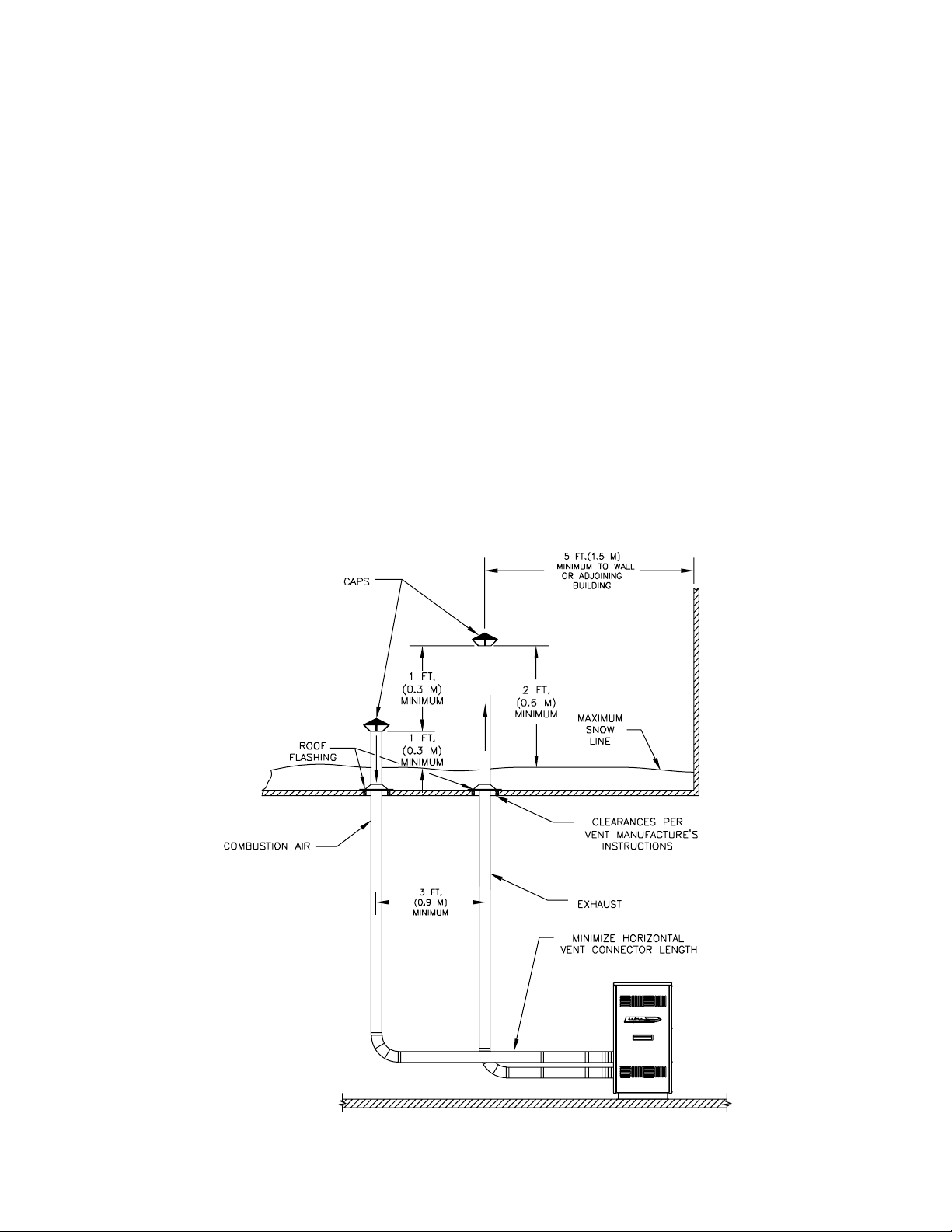
A listed, nonrestrictive intake air cap must be used. The
intake air cap must terminate as shown in Figure 6. The
penetration point in the roof must be properly flashed
and sealed.
Figure 6 - Vertical Positive Pressure Venting with Outdoor Combustion Air
Intake Air Optional - Horizontal Guidelines
The maximum equivalent length for the horizontal intake
air pipe is listed in Table 3. The intake air system must
be pitched down, toward the terminal, 1/4" per foot
(21 mm per meter).
If horizontal runs exceed 5 feet (1.5 m) they must be
supported at 3 foot (0.98 m) intervals with overhead
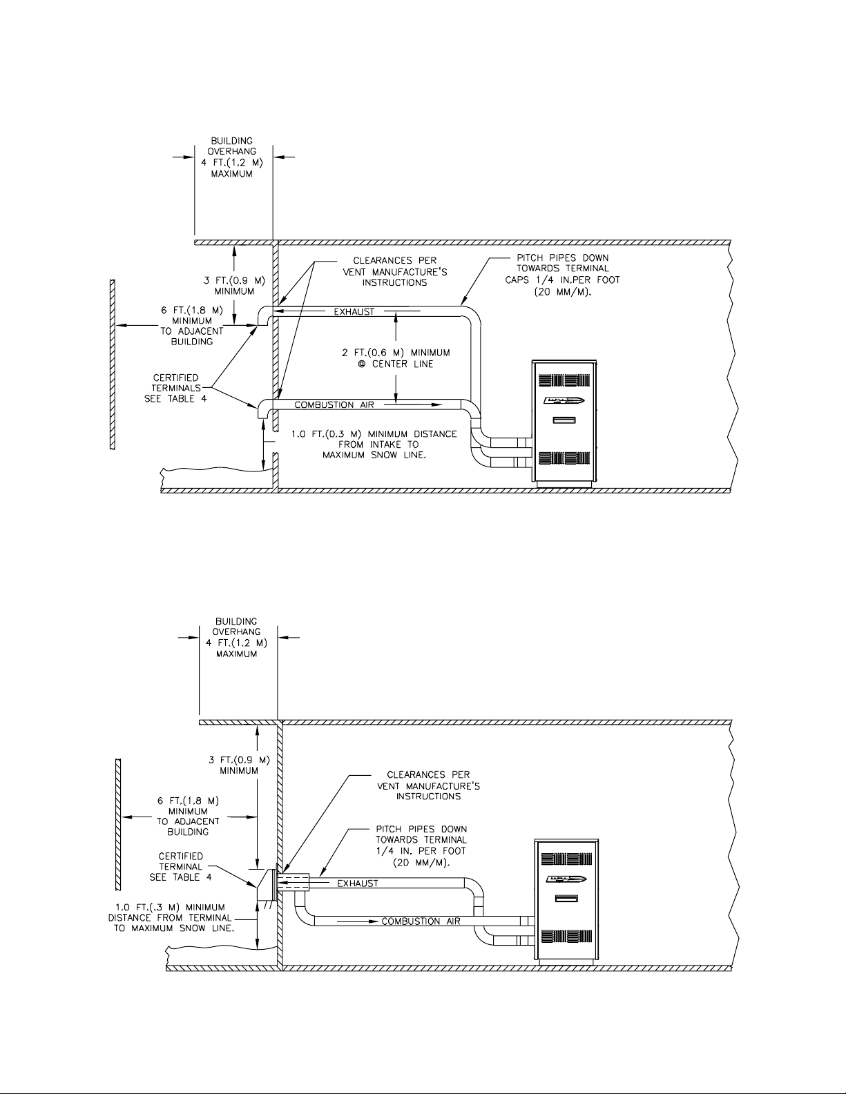
hangers. Figures 6 through 9 show the four horizontal
air intake options. The intake terminations certified for
use the FX are listed in Table 5.
Page 8
Page 8 FX DIRECT VENT BOILER INSTALLATION AND OPERATION INSTRUCTIONS
Figure 7 - Horizontal Positive Pressure Venting with Outdoor Combustion Air
Figure 8 - Horizontal Positive Pressure Concentric Venting with Outdoor Combustion
Page 9
FX DIRECT VENT BOILER INSTALLATION AND OPERATION INSTRUCTIONS Page 9
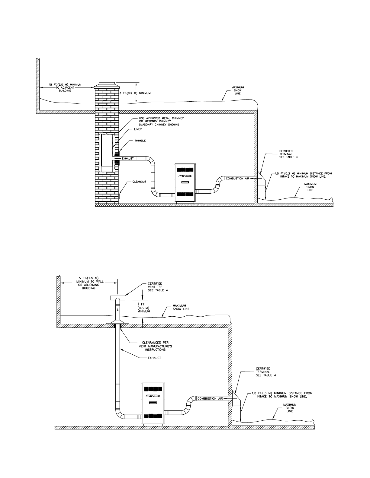
Figure 9 - Vertical Negative Pressure Masonry Chimney System using Outside Combustion Air
Figure 10 - Vertical Positive Pressure Venting using Outside Combustion Air
Page 10
Page 10 FX DIRECT VENT BOILER INSTALLATION AND OPERATION INSTRUCTIONS
GENERAL VENTING GUIDELINES
WARNING: The vent installation must be in
accordance with Part 7, Venting of Equipment,
of the National Fuel Gas Code, ANSI Z223.1/
NFPA 54-latest revision or applicable provisions
of the local building codes. Canadian
installations must comply with CSA B149.1 or
.2 Installation Code. Improper venting can result
in excessive levels of carbon monoxide which
can result in severe personal injury or death!
WARNING: Thimbles and fire-stops must be
used where required. A minimum clearance of
6" must be maintained between single wall
metal vents and combustible construction or a
fire resulting in severe personal injury or death
may occur!
WARNING : Each boiler/water heater must have
it's own vent system. Common positive pressure
vent systems are not to be used! Improper
installation can result in excessive levels of
carbon monoxide which can cause severe
personal injury or death!
All vent systems must be fully supported by the building
structure and not by the boiler/water heater.
VENT SYSTEM OPTIONS
The FX may be vented the following ways:
1) Direct Vent (Positive Pressure), uses a vent system
certified to UL 1738 for installations in the United States,
ULS636 for installations in Canada. Combustion air is
piped from the outdoors to the blower inlet.
GENERAL DIRECT VENT INFO
In this configuration the boiler blower is used to push
the flue products to the outdoors while drawing
combustion air from the outdoors. The instructions under
the COMBUSTION AIR & VENTILATION SECTION
must be followed! The vent system must be sized per
Table 3.
Table 3 - Positive Pressure Vent System Sizing
Boiler
Model
Number
FX-3
FX-4
FX-5
FX-6
FX-7
Equivalent Intake
Length (see note)
3” Diameter
45 feet (13.7 m)
45 feet (13.7 m)
45 feet (13.7 m)
n/a
n/a
Equivalent Intake
Length (see note)
4” Diameter
65 feet (19.8 m)
65 feet (19.8 m)
65 feet (19.8 m)
40 feet (12.2 m)
40 feet (12.2 m)
Note: Subtract 5 feet (1.5 m) for each 90° elbow.
HORIZONTAL DIRECT VENT
SYSTEMS
See figures 7 & 8. The vent materials used in horizontal
positive pressure vent systems must be certified to UL
1738 for installations in the United States, ULS636 for
installations in Canada. Certified vent systems are
manufactured by the following companies:
Heat-Fab, Inc.
130 Industrial Blvd., Turners Falls, MA 01376
(800) 772-0739.
Z-Flex U.S., Inc.
20 Commerce Park North, Bedford, NH 03110-6911
(800) 654-5600.
Protech Systems Inc.
26 Gansevoort Street, Albany, NY 12202
(518) 463-7284
2) Horizontal Vent (Positive Pressure), uses a vent
system certified to UL 1738 for installations in the United
States, ULS636 for installations in Canada. Combustion
air is obtained from the space in which the unit is
installed.
3) Vertical Vent (Positive Pressure), uses a vent
system certified to UL 1738 for installations in the United
States, ULS636 for installations in Canada. Combustion
air is piped from the outdoors to the blower inlet or is
obtained from the space in which the unit is installed.
4) Vertical/Chimney Vent (Negative Pressure), uses
an approved metal chimney system or masonry
chimney. Combustion air is obtained from the space in
which the unit is installed or is piped from the outdoors
to the blower inlet.
The maximum equivalent length for the horizontal vent
system is listed in Table 4. Each 90° elbow is equal to
5 linear feet (1.5 m) of pipe. To maximize the
performance of single wall sheet metal vent systems
locate 90° elbows as far from the boiler as possible and
from one another. For best results, horizontal vent
systems should be as short and straight as possible. The
vent system must be both gas tight and watertight. All
seams and joints in metal pipes must be joined and
sealed in accordance with the vent system
manufacturer’s instructions.
When horizontal vent runs exceed 5 feet (1.5m) they
must be supported at 3 foot (0.98 m) intervals with
overhead hangers. The vent system must be pitched
down, toward the v ent terminal, 1/4" per f oot (21mm per
meter). If any par t of a single wall metal vent system
passes through an unheated space it must be insulated
with insulation rated for 400°F. Structural penetrations
must be made using approved thimbles.
Page 11

FX DIRECT VENT BOILER INSTALLATION AND OPERATION INSTRUCTIONS Page 11
Horizontal vent systems shall terminate at least 4 feet
(1.3 m) below, 4 feet (1.3 m) horizontally from or 1 foot
(0.23 m) above any door, window or gravity air inlet into
any building. It must not terminate less than 4 feet (1.3
m) horizontally from, and in no case above or below,
unless a 4 feet (1.3 m) horizontal distance is maintained,
from electric meters, gas meters, regulators and relief
equipment and not less than 7 feet (2.3 m) from any
adjacent public walkway. The bottom of the vent
terminal(s) shall be located at least 5 feet (1.5 m) above
the air intake terminal(s). Avoid terminal locations likely
to be affected by winds, snowdrifts, people and pets.
The certified vent terminals listed in Table 4 must be
used. Protect building materials and vegetation from
degradation caused by the flue gases.
Table 4 - Certified Vent & Intake Terminals
Company
Protech
Protech
Protech
Protech
Protech
Protech
Protech
Protech
Field
Controls
Heat-Fab
Heat-Fab
Heat-Fab
Heat-Fab
Heat-Fab
Heat-Fab
Heat-Fab
Heat-Fab
Part No.
300311
300312
300186
300187
300130
300131
300160
300161
SWH-4”
CAT-4HG
7390GC
7490GC
7390TEE
7490TEE
7392GC
7492GC
7314TERM
7414TERM
Description
Tee
Tee
Bird Screen
Bird Screen
45° Elbow
45° Elbow
90° Elbow
90° Elbow
Vent Hood
Air T ee
Mitered
Mitered
Tee
Tee
Screen
Screen
90° Elbow
90° Elbow
Dia. (in.)
3
4
3
4
3
4
3
4
4
4
3
4
3
4
3
4
VERTICAL DIRECT VENT SYSTEMS
See Figures 6 & 10. The vent materials used in vertical
positive pressure vent systems must be certified to UL
1738 for installations in the United States, ULS636 for
installations in Canada. Certified vent systems are
manufactured by the following companies:
Heat-Fab, Inc.
130 Industrial Blvd., Turners Falls, MA 01376
(800) 772-0739.
Z-Flex U.S., Inc.
20 Commerce Park North, Bedford, NH 03110-6911
(800) 654-5600.
Protech Systems Inc.
26 Gansevoort Street, Albany, NY 12202
(518) 463-7284
The maximum length for the vertical vent system is listed
in Table 4. Each 90° elbow is equal to 5 linear feet (1.5
m) of pipe. To maximize the performance of single wall
sheet metal vent systems locate 90° elbows as f ar from
the boiler as possible and from one another. If any part
of a single wall metal vent system passes through an
unheated space it must be insulated with insulation
rated for 400°F. Structural penetrations must be made
using approved fire-stops.
The vent system must be both gas tight and watertight.
All seams and joints in metal pipes must be joined and
sealed in accordance with the vent system
manufacturer’s instructions.
Vertical vent systems must be terminated with an
approved terminal cap as shown in Figures 6 & 10.
HORIZONT AL VENT
POSITIVE PRESSURE SYSTEMS
See Figure 3. The vent materials used in horizontal
positive pressure vent systems must be certified to UL
1738 for installations in the United States, ULS636 for
installations in Canada. Certified vent systems are
manufactured by the following companies:
Heat-Fab, Inc.
130 Industrial Blvd., Turners Falls, MA 01376
(800) 772-0739.
Z-Flex U.S., Inc.
20 Commerce Park North, Bedford, NH 03110-6911
(800) 654-5600.
Protech Systems Inc.
26 Gansevoort Street, Albany, NY 12202
(518) 463-7284
The maximum equivalent length for the horizontal vent
system is listed in Table 4. Each 90° elbow is equal to
5 linear feet (1.5 m) of pipe. To maximize the
performance of single wall sheet metal vent systems
locate 90° elbows as far from the boiler as possible and
from one another. Horizontal vent systems should be as
short and straight as possible.
When horizontal vent runs exceed 5 feet (1.5 m) they
must be supported at 3 foot (0.98 m) intervals with
overhead hangers. The vent system must be pitched
down, toward the vent ter minal, 1/4" per foot (21 mm
per meter). If any part of a single wall metal vent system
passes through an unheated space it must be insulated
with insulation rated for 400°F. Structural penetrations
must be made using approved thimbles.
The vent system must be both gas tight and watertight.
All seams and joints in metal pipes must be joined and
sealed in accordance with the vent system
manufacturer's instructions.
Page 12
Page 12 FX DIRECT VENT BOILER INSTALLATION AND OPERATION INSTRUCTIONS
Horizontal vent systems shall terminate at least 4 feet
(1.3 m) below, 4 feet (1.3 m) horizontally from or 1 foot
(0.23 m) above any door, window or gravity air inlet into
any building. It must not terminate less than 4 feet (1.3
m) horizontally from, and in no case above or below,
unless a 4 feet (1.3 m) horizontal distance is maintained,
from electric meters, gas meters, regulators and relief
equipment and not less than 7 feet (2.3 m) from any
adjacent public walkway. The bottom of the vent
terminal(s) shall be located at least 5 feet (1.5 m) above
the air intake terminal(s). Avoid terminal locations likely
to be affected by winds, snowdrifts, people and pets.
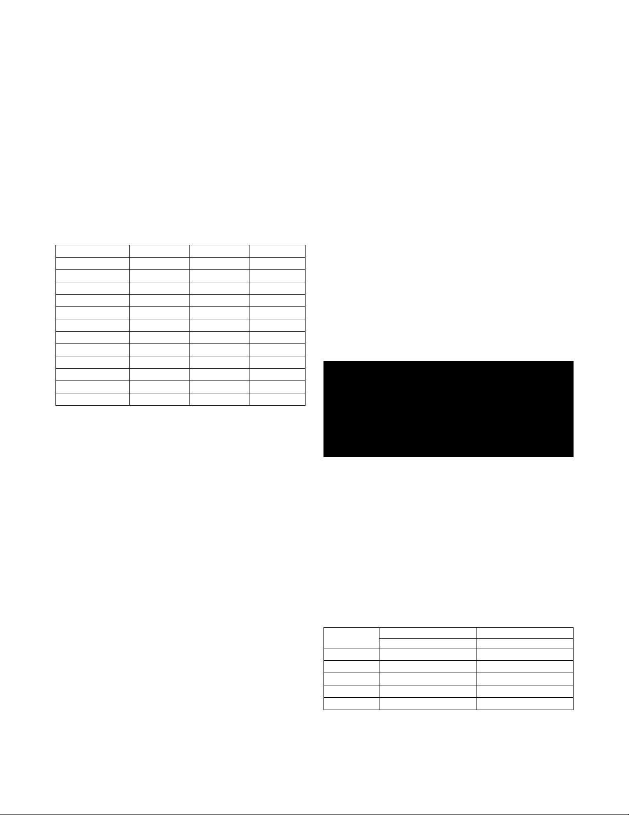
Table 5 - Certified Vent Terminals
Company
Protech
Protech
Protech
Protech
Protech
Protech
Field
Field
Heat-Fab
Heat-Fab
Heat-Fab
Heat-Fab
Part No.
300311
300312
300130
300131
300160
300161
SWH-3’’
SWH-4’’
7390TEE
7490TEE
7314TERM
7414TERM
Description
Tee
Tee
45° Elbow
45° Elbow
90° Elbow
90° Elbow
Vent Hood
Vent Hood
Tee
Tee
90° Elbow
90° Elbow
Dia. (in.)
3
4
3
4
3
4
3
4
3
4
3
4
The certified vent terminals listed in Table 5 must be
used. Protect building materials and vegetation from
degradation caused by the flue gases.
The maximum length for the vertical vent system is listed
in Table 4. Each 90° elbow is equal to 5 linear feet (1.5
m) of pipe. To maximize the performance of single wall
sheet metal vent systems locate 90° elbows as f ar from
the boiler as possible and from one another. If any part
of a single wall metal vent system passes through an
unheated space it must be insulated with insulation
rated for 400 °F. Structural penetrations must be made
using approved fire-stops.
The vent system must be both gas-tight and watertight.
All seams and joints in metal pipes must be joined and
sealed in accordance with the vent system
manufacturer's instructions. Vertical vent systems must
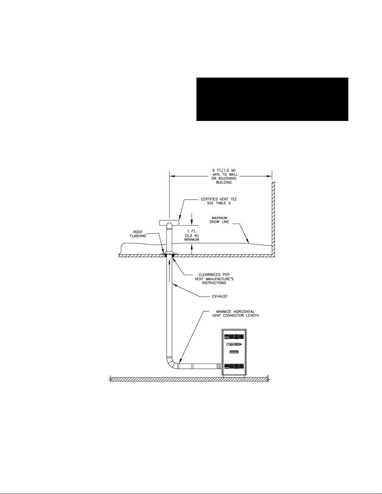
terminate as shown in Figures 6 & 11. An approved
terminal cap must be used.
VERTICAL VENT
NEGATIVE PRESSURE SYSTEMS
See Figures 4, 5 & 9. The FX is listed as a Category I
appliance when vented vertically into a metal chimney
system or masonry chimney sized as listed in Table 7.
WARNING: If an appliance using any type of a
mechanical draft system operating under
positive pressure is connected to a chimney
flue, never connect an y other appliances to this
flue. Doing so can result in excessive levels of
carbon monoxide which can cause severe
personal injury or death!
VERTICAL VENT
POSITIVE PRESSURE SYSTEMS
See Figure 11. The vent materials used in vertical
positive pressure vent systems must be certified to UL
1738 for installations in the United States, ULS636 for
installations in Canada. Certified vent systems are
manufactured by the following companies:
Heat-Fab, Inc.
130 Industrial Blvd., Turners Falls, MA 01376
(800) 772-0739.
Z-Flex U.S., Inc.
20 Commerce Park North, Bedford, NH 03110-6911,
(800) 654-5600.
Protech Systems Inc.
26 Gansevoort Street, Albany, NY 12202
(518) 463-7284
Chimney Inspection & Sizing
A thorough inspection of the masonry chimney must be
performed to ensure that the chimney is clean, properly
constructed and properly sized. Exterior masonry
chimneys should not be used unless properly lined to
prevent condensation and draft problems. Table 4 lists
the equivalent breeching and flue sizes required for the
boiler/water heater. When more than one appliance is
connected to the same chimney flue the flue must be
large enough to safely vent the combined output of all
of the appliances.
Table 6 - Vent, Intake & Equivalent Chimney Size
Boiler
Model
FX-70
FX-105
FX-140
FX-175
FX-210
Vent & Chimney Diameter Intake Diameter
3 (7.6)
4 (10.2)
4 (10.2)
5 (12.7)
5 (12.7)
inches (mm)inches (mm)
3 (7.6)
3 (7.6)
3 (7.6)
4 (10.2)
4 (10.2)
Note: These sizes are based on a 20 foot (6.1m)
chimney height.
Page 13
FX DIRECT VENT BOILER INSTALLATION AND OPERATION INSTRUCTIONS Page 13
The vent connector should be sloped up toward the
chimney 1/4" per foot. Ensure that the vent connector
is properly supported and each connection securely
fastened with at least 3 corrosion resistant sheet metal
screws. The termination of the vent pipe must be flush
with the inside of the chimney flue.
CAUTION: The vent connector length must never
exceed 3/4 of the height of the chimney or venting
problems will occur!
Figure 11 - Vertical Positive Pressure Venting
Always provide a minimum clearance of 6 inches
between single wall metal vent pipe and any combustible
materials. Type B1 vent may be used, clearance betw een
it and any combustible material must be as listed.
WARNING: Failure to maintain minimum
clearances between vent connectors and
combustible materials can result in a fire causing
extensive property damage, severe personal
injury or death!
Page 14

Page 14 FX DIRECT VENT BOILER INSTALLATION AND OPERATION INSTRUCTIONS
COMMON VENT SYSTEMS
WARNING: DO NOT connect this boiler or any
other appliance using a positive pressure
common vent system or a mechanical draft
system! Failure to comply with this WARNING
could result in the accumulation of carbon
monoxide gas which can cause severe per sonal
injury or death!
If an existing boiler/water heater is removed from a
common venting system, the common venting system
may then be too large for the proper venting of the
remaining appliances connected to it. At the time of
removal of an existing boiler/water heater, the following
steps shall be followed with each appliance remaining
connected to the common venting system placed in
operation, while the other appliances remaining
connected to the common venting system are not in
operation.
Au moment du retrait d'une chaudière existante, les
mesures suivantes doivent être prises pour chaque
appareil toujours raccordé au système d'évacuation
commun et qui fonctionne alors que d'autres appareils
toujours raccordés au système d'évacuation ne fonctionnent pas: système d'évacuation
Dans la mesure du possible, fermer toutes les
portes et les fenêtres du bâtiment et toutes les
portes entre l'espace où les appareils toujours
raccordés du système d'évacuation sont installés et
les autres espaces du bâtiment. Mettre en marche
les sécheuses, tous les appareils non raccordés au
système d'évacuation commun et tous les
ventilateurs d'extraction comme les hottes de
cuisinère et les ventilateurs des salles de bain.
S'assurer que ces ventilateurs fonctionnent à la
vitesse maximale. Ne pas faire fonctionner les
ventilateurs d'été. Fermer les registres des
cheminées.
d) Place in operation the appliance being inspected.
Follow the lighting instructions. Adjust thermostat so
appliance will operate continuously.
Mettre l'appareil inspecté en marche. Suivre les
instructions d'allumage. Régler le thermostat de
façon que l'appareil fonctionne de façon continue.
e) Test f or spillage at the dr aft hood relief opening after
5 minutes of main burner operation. Use the flame
of a match or candle, or smoke from a cigarette,
cigar or pipe.
a) Seal any unused openings in the common venting
system.
Sceller toutes les ouvertures non utilisées du sys-
tème d'évacuation.
b) Visually inspect the venting system for proper size
and horizontal pitch and determine there is no
blockage or restriction, leakage, corrosion and other
deficiencies which could cause an unsafe condition.
Inspecter de façon visuelle le système d'évacu-ation
pour déterminer la grosser et l'inclinaison
horizontale qui conviennent et s'assurer que le
système est exempt d'obstruction, d'étranglement
de fruite, de corrosion et autres défaillances qui
pourraient présenter des risques.
c) Insofar as is practical, close all building doors and
windows and all doors between the space in which
the appliances remaining connected to the common
venting system are located and other spaces of the
building. Turn on clothes dryers and any appliance
not connected to the common venting system. Turn
on any exhaust fans, such as range hoods and
bathroom exhaust, so they will operate at maxim um
speed. Do not operate a summer exhaust fan for a
boiler installation. Close fireplace dampers.
Faire fonctionner le brûleur principal pendant 5 min
ensuite, déterminer si le coupe-tirage déborde à
l'ouverture de décharge. Utiliser la flamme d'une
allunette ou d'une chandelle ou la fumée d'une
cigarette, d'un cigare ou d'une pipe.
f) After it has been determined that each appliance
remaining connected to the common venting system
properly vents when tested as outlined above, return
doors, windows, exhaust fans, fireplace dampers
and any other gas-burning appliance to their
previous condition of use.
Une fois qu'il a été d éterminé, selon la métode
indiquée ci-dessus, que chaque appareil raccordé
au système d'évacuation est mis à l'air libre de façor
adéquate. Remettre les por tes et les fenêtres, les
ventilateurs, les registres de cheminées et les
appareils au gaz à leur position originale.
g)
Any improper operation of the common venting
system should be corrected so the installation
conforms with the National Fuel Gas Code, ANSI
Z223.1/NFPA 54. When resizing any portion of the
common venting system, the common venting system
should be resized to approach the minimum size as
determined using the appropriate tables in Appendix
F in the National Fuel Gas Code, ANSI Z223.1/ NFPA
54 and or CSA B149 Installation Codes.
Page 15
FX DIRECT VENT BOILER INSTALLATION AND OPERATION INSTRUCTIONS Page 15
Tout mauvais fonctionnement du systéme d'évacution commun devrait étré corrigé de façor que
l'installation soit conforme au National Fue Gas Code,
ANSI Z223.1/NFPA 54 et (ou) aux codes d'installation CSA-B149. Si la g rosseur d'une section du
système d' évacuation doit étré modifiée, le système
devrait étré modifié pour respecter les valeurs
minimales des tableaux pertinents de l'appendice F
du National Fuel Gas Code, ANSI Z223.1/ NFPA 54
et (ou) des codes d'installation CSA-B149.
CONDENSATE PIPING
A small amount of condensate is generated on start up.
To prevent an excess amount of condensate collecting
in the flue collector a condensate drain has been
provided. A condensate trap or pump MUST be
connected to the condensate fitting in the bottom of the
flue collector.
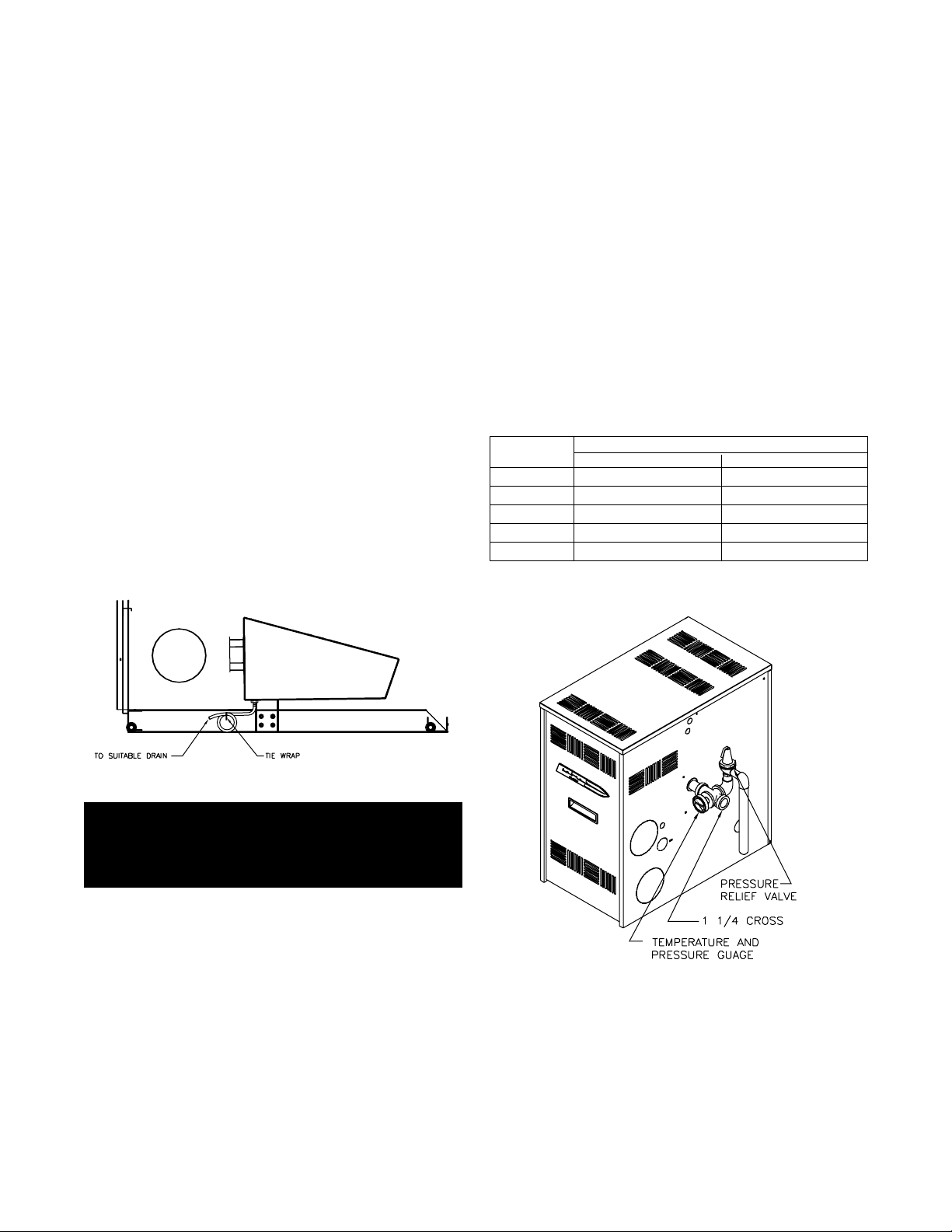
A trap can be made by tie wrapping a 4” loop in a piece
of vinyl hose attached to the condensate drain fitting.
The trap must be filled with water to prevent flue gasses
from escaping, see Figure 12.
Figure 12 - Condensate Trap
HEATING SYSTEM PIPING
CAUTION: All heating system piping must be
installed in accordance with the ANSI/ASME Boiler
and Pressure Vessel Code, Section IV. All applicable
local codes and ordinances must also be followed.
If the boiler is installed above any radiation
elements it must be fitted with a low water cutoff
device installed above the normal boiler water level!
The FX hot water boiler comes from the factory ready
to be piped to the heating system. Each boiler is
equipped with a safety relief valve which must be piped
in accordance with the ANSI/ASME Boiler and Pressure
Vessel Code, Section IV, see Figure 13.
Table 7 - Boiler Water Volume
Boiler
Model
FX-3
FX-4
FX-5
FX-6
FX-7
Figure 13 - Relief Valve Piping
1.8
2.4
3.0
3.6
4.2
Water V olume
Liters Gallons
6.8
9.1
11.4
13.6
15.9
WARNING: Failure to connect a condensate trap
or pump to the flue collector can result in
excessive levels of carbon monoxide whic h can
cause severe personal injury or death!
Ensure that the boiler is level from front to bac k and from
side to side. Use metal shims to level the boiler. NEVER
use combustible materials for shims.
Page 16
Page 16 FX DIRECT VENT BOILER INSTALLATION AND OPERATION INSTRUCTIONS
Bypass Piping
CAUTION: Never connect this boiler directly to a
large volume system, in-floor radiant system, snow
melt system or any other system that would cause
the steady state water temperature in the boiler to
drop below 140°F. To prevent damage due to
excessive condensation, one of the following piping
options must be used or the boiler warranty will be
voided!
CAUTION: The blend pump arrangement shown in
Figure 16 must be used when flow from any zone
in a multiple zone system is less than 4 GPM or
boiler short cycling on the high limit will occur!
For the three systems listed below, adjust the bypass
valve to diver t some of the heated water back into the
boiler's return piping. When adjusted correctly the
temperature of the boiler water will exceed 140°F within
five minutes of a warm start. A plug valve should be
used as the bypass valve for best system performance.
NOTE: Some of the circulator's capacity will be used
in the blending process for the first two systems.
Large heating systems may require a larger
circulator.
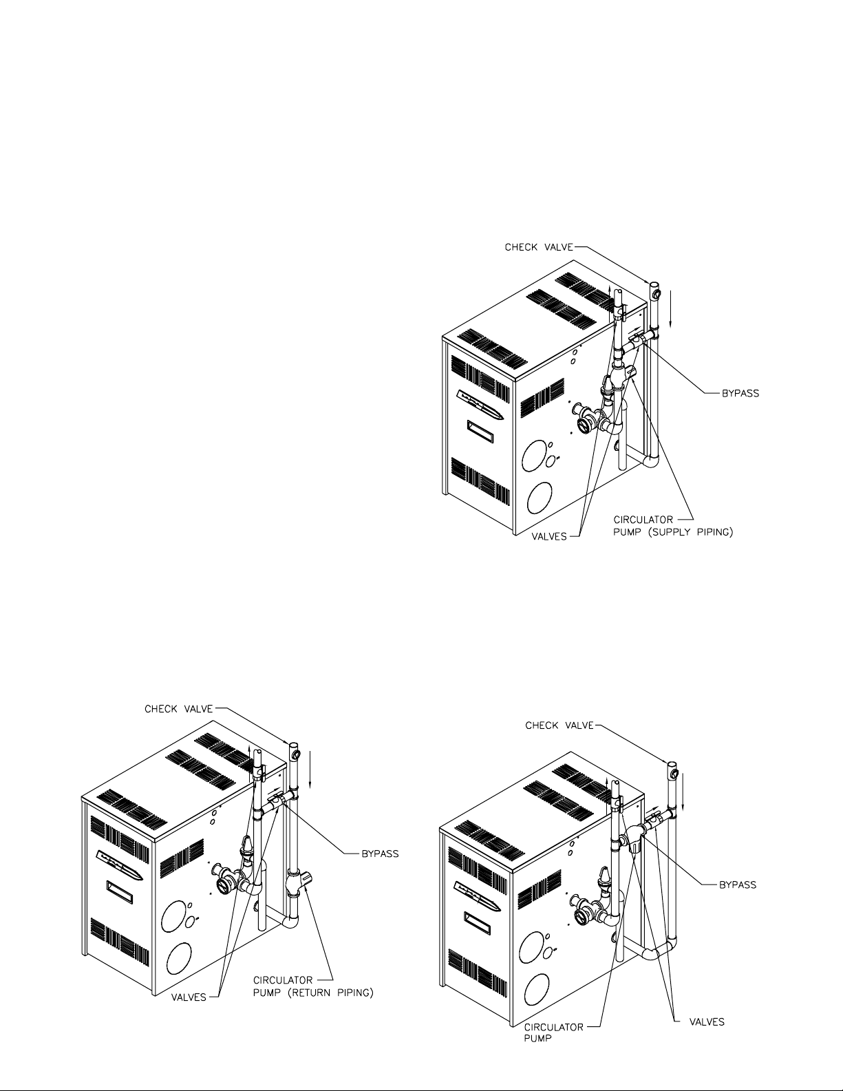
Pump Away Bypass
The system bypass shown in Figure 15 should be used
on single zone systems, or multiple zone systems using
zone valves, when the circulator is installed in the supply
piping. The bypass must be installed between the supply
and return pipes on the pressure side of the circulator.
Figure 15 - Pump Away Bypass Piping
System Bypass
The system bypass shown in Figure 14 should be used
on single zone systems, or multiple zone systems using
zone valves, when the circulator is installed in the return
piping. The bypass must be installed between the supply
and return pipes on the suction side of the circulator.
Figure 14 - System Bypass Piping
Pumped Blend Bypass
The system bypass shown in Figure 16 should be used
on multiple zone systems. The bypass must be installed
between the supply and return pipes on the suction side
of the zone circulators. The bypass valve must be
installed on the pressure side of the bypass circulator.
Figure 16 - Pumped Bypass Piping
Page 17
FX DIRECT VENT BOILER INSTALLATION AND OPERATION INSTRUCTIONS Page 17
Piping For Use With Cooling Units
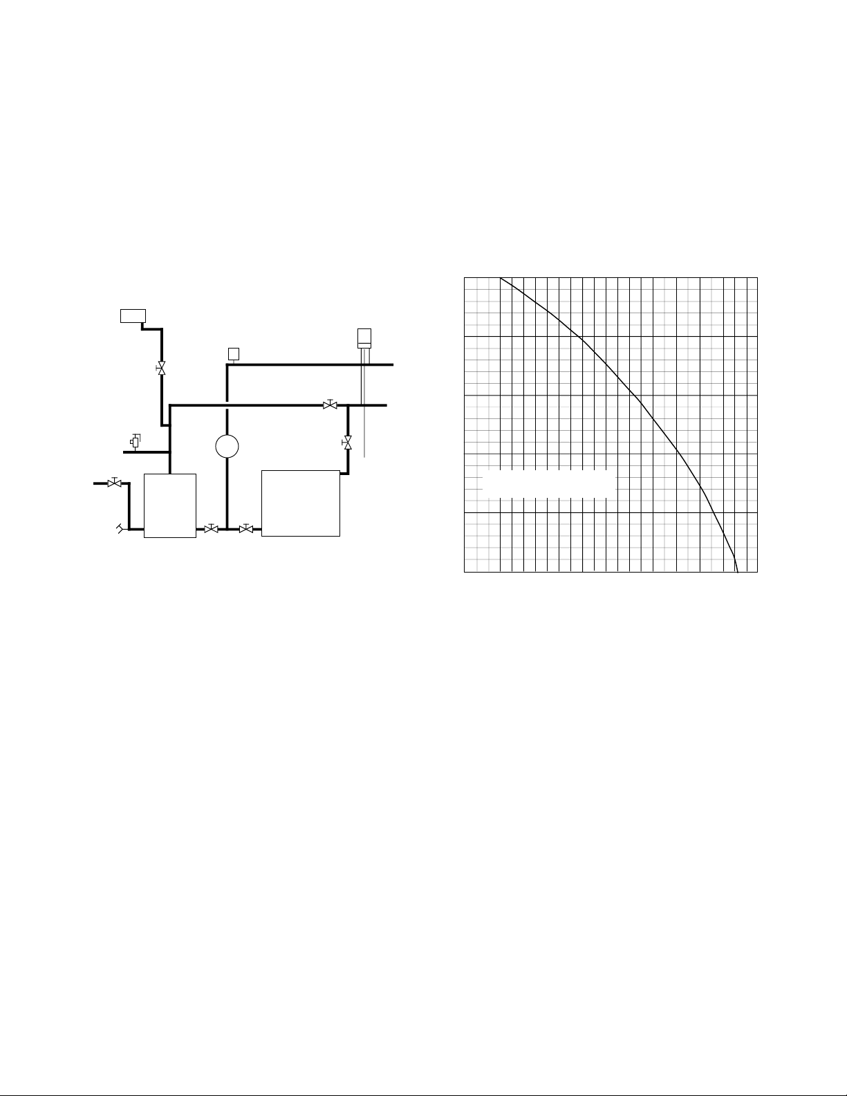
The boiler, when used in connection with a refrigeration system must be installed so the chilled medium is
piped in parallel with the boiler. Appropriate valves must
be used to prevent the chilled water from entering the
boiler. See Figure 17 for the proper piping layout.
Figure 17 - Chiller Schematic
FOR HEATING: VALVES "H" OPEN, VALVES "C" CLOSED.
FOR COOLING: VALVES "H" CLOSED, VALVES "C" OPEN.
EXP. TANK
RELIEF
VALVE
FILL
VALVE
DRAIN
BOILER
NOTE
ROOM
UNIT
VENT
H
PUMP
H
C
CHILLER
C
DRAIN
Circulators
The TACO 007 circulator supplied with the boiler is sized
for use in a closed heating system with a 30 psi
maximum operating pressure. If the 007 circulator does
not have the required capacity for the system in which
it is to be installed, an extra zone circulator or a higher
capacity circulator will be needed. Figure 18 depicts the
performance curve for the TACO 007 circulator.
Figure 18 - TACO 007 Performance Curve
10
8
6
4
HEAD - FEET OF WATER
TACO 007 CIRCULATOR
PERFORMANCE CURVE
2
When a boiler is connected to a heating coil that may be
exposed to refrigerated air from an air handling device, the
piping system must be equipped with flow-control valv es or
some other automatic means of preventing gravity
circulation of the boiler water during the cooling cycle.
0
0 5 10 15 20 25
FLOW - GPM
Page 18
Page 18 FX DIRECT VENT BOILER INSTALLATION AND OPERATION INSTRUCTIONS
GAS SUPPLY PIPING
The FX hot water boiler comes from the factory ready
to be piped to the gas supply. The gas supply can be
piped from the left or right side of the boiler.
If for any reason the boiler is not for the type of gas
available at the installation site, call the nearest
Hydrotherm distributor to resolve the problem.
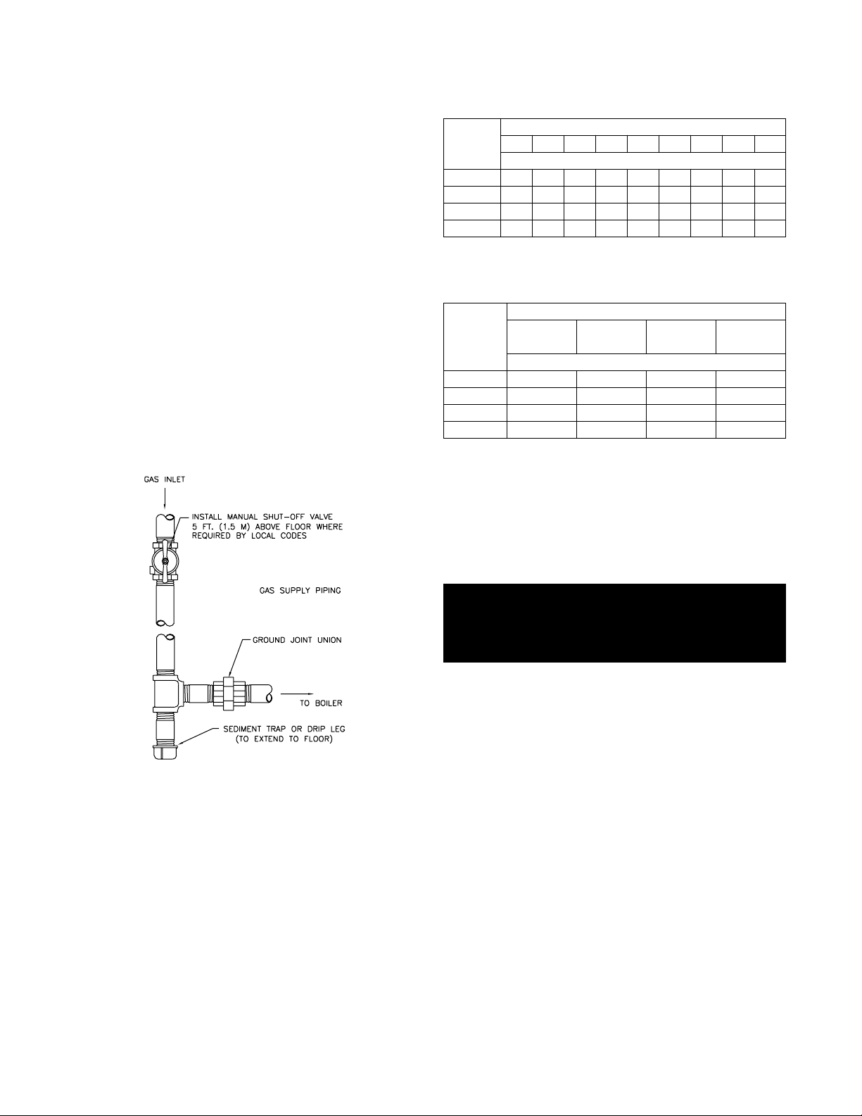
Figure 19 depicts the proper way to connect the boiler to
the gas supply piping. The manual shut-off valve MUST
be installed in the supply piping. It should be
approximately 5 feet abo ve the floor . Provide a sediment
trap/drip leg at the bottom of the vertical section of the
gas supply pipe. A ground joint union should be installed
between the boiler gas controls and the supply piping.
Each of these items is needed to ensure long life and
ease of servicing. Always use a pipe sealant that is
suitable for use with LP gas.
Figure 19 - Gas Supply Piping
Table 8 - Gas Pipe Capacity
Nominal
Iron Pipe
Size, (in)
3
1″
11/4″
11/2″
Note: Maximum pipe capacity in ft3/hr is based on a 0.60 specific
gravity gas at a pressure of 0.5 psig and a 0.3" WC pressure drop.
10 20 30 40 50 60 80 100 150
278 190 152 130 115 105 90 79 64
/4″
520 350 285 245 215 195 170 150 120
1050 730 590 500 440 400 350 305 250
1600 1100 890 760 670 610 530 460 380
Pipe length in feet
Gas pipe Capacity (ft3/hr)
Table 9 - Equivalent Pipe Length Chart
Nominal
Iron Pipe
Size, (in)
3
/4″
1″
11/4″
11/2″
90° Elbow
Equivalent length of pipe fitting in feet
2.6 5.2 0.6 1.5
3.5 6.9 0.8 1.9
4.0 8.0 0.9 2.3
5.2 10.3 1.2 3.0
Type of pipe fitting
T ee Gas Valv e
(branch flow)
(full port)
Gas Cock
Whenever the gas supply piping is pressure tested the
boiler gas controls must be protected. If the test pressure is equal to, or less than 1/2 psig (3.5 kPa) isolate
the boiler by closing it's manual shut off valve, see
Figure 8. If the test pressure is g reater than 1/2 psig (3.5
kPa), disconnect the boiler and it's individual shut-off
valve from the gas supply piping.
CAUTION: Always use a wrench on the gas valve
body when making gas connections to it. Never
over-tighten the piping entering the gas valve body
or the gas valve will be damaged!
Table 8 should be used to ensure that the gas supply
piping is sized properly. If more than one appliance is
supplied by the same supply pipe, the piping must be
sized based on the maximum possible demand. Do not
neglect the pressure drop due to pipe fittings. Table 9
should be used in conjunction with Table 8 to ensure
that the gas supply piping is sized properly.
Safe lighting and other performance criteria were met
with the gas manifold and control assembly provided on
the boiler when the boiler underwent tests specified in
ANSI Z21.13. All gas connections MUST be leak tested
before putting the boiler into operation.
WARNING: Never use an open flame to test for
gas leaks. Always use an approved leak
detection method. Failure to comply with this
WARNING could result in an explosion!
ELECTRICAL WIRING
CAUTION: Label all wires prior to disconnection
when servicing controls. Wiring errors can cause
improper and dangerous operation!
ATTENTION: Au moment de l'entretien des
commandes, étiquetez tous les fils avant de les
débrancher. Des erreurs de câblage peuvent
entraîner un fonctionnement inadéquat et
dangereux. S'assurer que l'appareil fonctionne
adéquatement une fois l'entretirn terminé.
The electrical connections to this boiler/water heater
must be made in accordance with all applicable local
codes and the latest revision of the National Electrical
Code, ANSI /NFPA-70. Installation should also conform
with CSA C22.1 Canadian Electrical Code Part I if
installed in Canada. Install a separate 120 volt 15 amp
circuit for the boiler. A properly rated shut-off switch
should be located at the boiler. The boiler must be
grounded in accordance with the authority having
jurisdiction, or if none, the latest revision of the National
Electrical Code, ANSI/NFPA-70.
Page 19

FX DIRECT VENT BOILER INSTALLATION AND OPERATION INSTRUCTIONS Page 19
Line voltage field wiring of any controls or other devices
must use copper conductors with a minimum size of #14
awg. Low voltage wiring must not be less than #18 awg
with a neoprene, thermoplastic or other equivalent
insulation having a minimum insulation thickness of
0.012 inches.
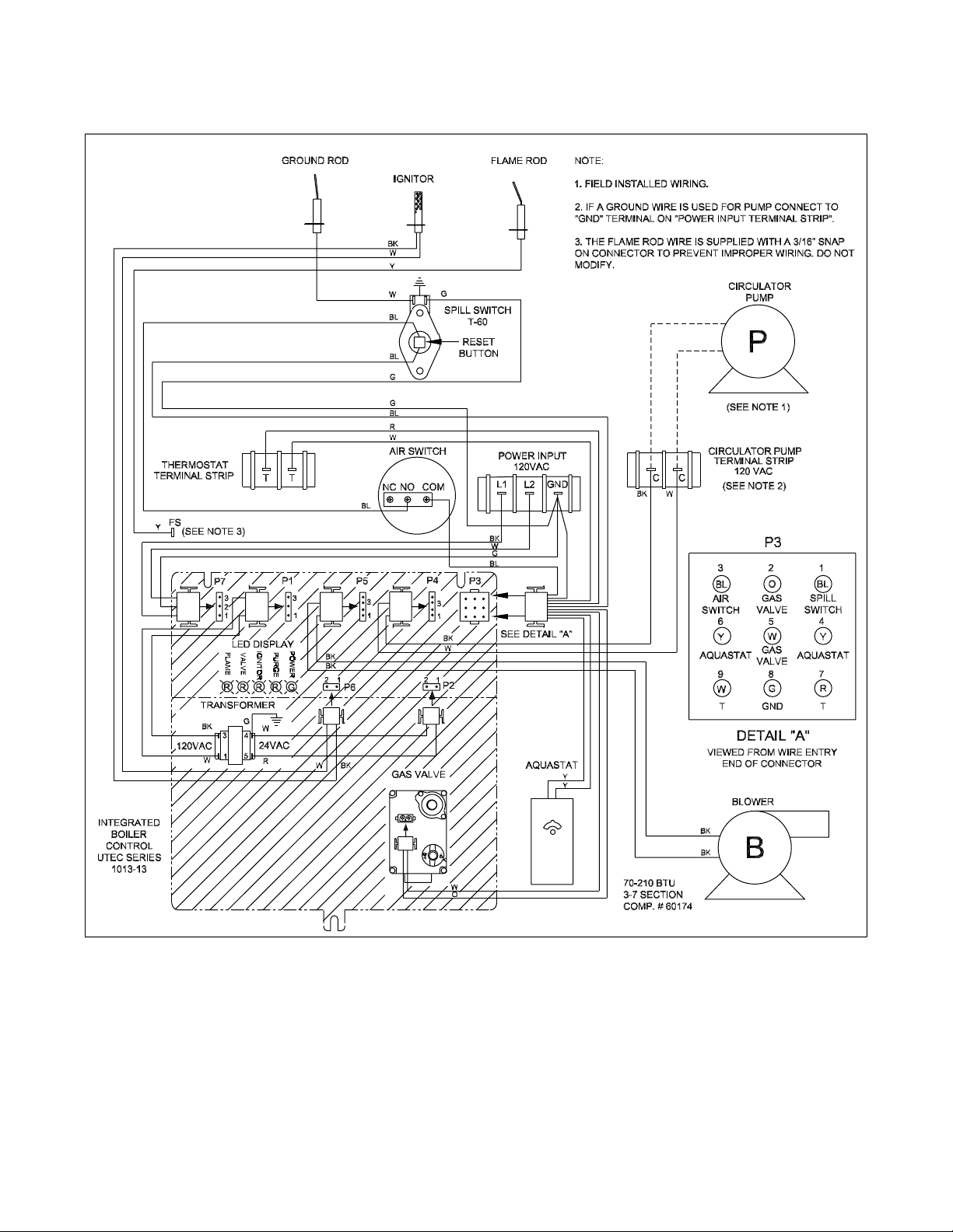
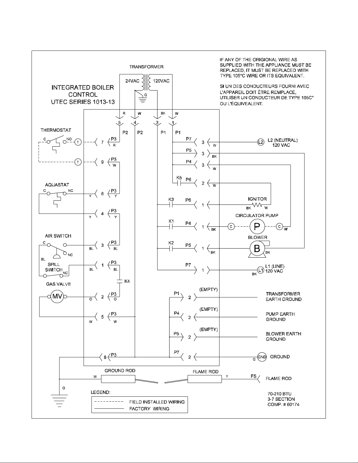
Refer to Figures 20A and 20B for proper wiring
connections.
Thermostat Installation
ALWAYS follow the instructions included with the thermostat to be used to control the boiler. Proper location
of the thermostat will ensure efficient trouble-free
operation of the boiler. Mount the thermostat to an inside
wall at a height approximately five feet above the floor.
Avoid placing the ther mostat in areas that will not provide an accurate measurement of the room temperature.
Locating the thermostat behind a door, in an alcove,
close to a source of thermal radiation or in a drafty area
will cause poor or sporadic heating.
OPERATIONAL SEQUENCE
The control energizes the circulator motor when the
thermostat contacts are closed. The control then checks
that the limit switch is closed, if not the control will wait
for the limit switch to close. With the limit switch closed
the pressure switch contacts are checked. If the
pressure switch contacts are open the blower motor is
energized. If the pressure switch contacts aren’t open
the control will wait 45 seconds then lock out. The
PURGE light will flash to indicate a pressure switch fault.
Also, if the pressure switch does not close within 5
minutes of the blower being turned on, the control will
lock out with the PURGE light flashing to indicate a
pressure switch fault.
Once the flame has been proven, the system is in
Steady-State heating mode. The control will continuously
monitor the thermostat, limit switch, pressure switch, and
flame sense. If the thermostat opens, the control will
de-energize the gas valve and begin post-purge. If the
limit switch opens, the control will de-energizes the gas
valve, run through post-purge, and wait for the limit
switch to re-close before attempting re-ignition. If flame
is lost, the control will de-energize the gas valve, run
through post-purge, and go to pressure switch proving
mode for re-ignition. If the pressure switch opens for
more than 0.1 seconds the inducer is turned off for 30
seconds, then the control goes to the pressure switch
proving mode for a re-ignition attempt.
When the thermostat is satisfied the post purge period
starts. A post-purge will be performed at any time the
gas valve has been on and is turned off, except for loss
of pressure switch, when a post-purge would be
ineffective. The post-purge must be completed before a
new ignition sequence can start.
In the event that the flame signal is lost after the flame
has been proven, the system will turn off the gas valve
within 2.0 seconds, perform the post-purge, and repeat
the ignition sequence. As a preventative measure to
avoid nuisance shutdown due to a flickering flame, the
flame must be lost for a minimum of 0.5 seconds.
Control Outputs:
Induced draft blower - 1.75 Amps @ 120 VAC.
Circulator Pump - 2.7 Amps @ 120 VAC.
Hot Surface Igniter - 5.0 Amp resistive @ 120 VAC.
Gas Valve - 0.6 Amp @ 24 VAC, 0.45 power factor.
The pre-purge period begins when the pressure switch
contacts close. At the end of the pre-purge period, the
control energizes the HSI igniter for an HSI warm-up
period. This condition will be indicated by illumination of
the IGNITER light. A one second trial f or ignition will take
place. In the event ignition is not achieved by the end of
the first trial for ignition period, the control will run through
a post purge and then de-energize the inducer. When
the pressure switch contacts open the control will begin
a new ignition sequence. Failure to establish flame after
the third attempt will result in ignition lock-out and the
VALVE light on the control will flash.
Page 20
Page 20 FX DIRECT VENT BOILER INSTALLATION AND OPERATION INSTRUCTIONS
Figure 20A - Wiring Connection Diagram
Page 21
FX DIRECT VENT BOILER INSTALLATION AND OPERATION INSTRUCTIONS Page 21
Figure 20B - Wiring Ladder Diagram
Page 22
Page 22 FX DIRECT VENT BOILER INSTALLATION AND OPERATION INSTRUCTIONS
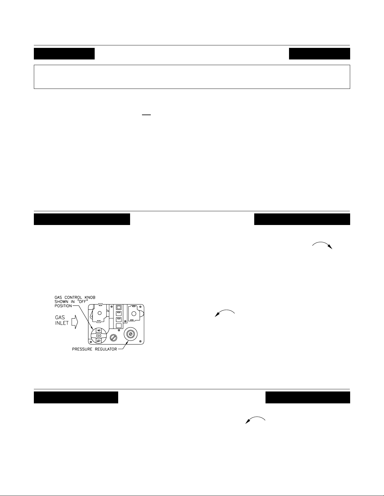
FOR YOUR SAFETY READ BEFORE OPERATING
WARNING: If you do not follow these instrucitons exactly, a fire or explosion may result
causing property damage, personal injury or loss of life.
A. This appliance does not have a pilot. It is
equipped with an ignition device which
automatically lights the burner. Do not try to light
the burner by hand.
B. BEFORE OPERATING smell all around the
appliance area for gas. Be sure to smell next to
the floor because some gas is heavier than air
and will settle on the floor.
WHAT TO DO IF YOU SMELL GAS
• Do not try to light any appliance.
• Do not tough any electric switch; do not use any
phone in your building.
• Immediately call your gas supplier from a neighbor's
phone. Follow the gas suppliers instructions.
OPERATING INSTRUCTIONS
1. STOP! Read the safety information above.
2. Turn off all electric power to the appliance.
3. Set the thermostat to lowest setting.
4. This appliance is equipped with an ignition device,
which automatically lights the burner. Do not try
to light the burner by hand!
• If you cannot reach your gas supplier, call the fire
department.
C. Use only your hand to push in or turn the gas
control knob. Never use tools. If the knob will not
push in or turn by hand, don't try to repair it, call
a qualified service technician. Force or attempted
repair may result in a fire or explosion.
D. Do not use this appliance if any par t has been
under water. Immediately call a qualified service
technician to inspect the appliance and to replace
any part of the control system and any gas control
that has been under water.
5. Remove control access panel.
6. Turn the gas control knob clockwise to the
full “OFF” position, on the White Rodgers 36E
push the knob before turning it.
7. Wait five (5) minutes to clear out any gas. If you
then smell gas STOP! Follow “B” in the safety
information above. If you don't smell gas, go to
the next step.
TO TURN OFF GAS TO APPLIANCE
1. Turn off all electric power to the appliance.
2. Set the thermostat to lowest setting.
3. Remove control access panel.
8. Turn the gas control knob counterclockwise
to “ON”.
9. Replace control access panel.
10. Turn on all electric power to the appliance.
11. Set thermostat to desired setting.
12. If the appliance will not operate, follow the
instructions “TO TURN OFF GAS TO
APPLIANCE” and call your service technician or
gas supplier.
4. Push in gas control knob slightly and turn
clock-wise to “OFF”. Do not force.
5. Replace control access panel.
Page 23
FX DIRECT VENT BOILER INSTALLATION AND OPERATION INSTRUCTIONS Page 23
POUR VO TRE SÉCURITÉ LISEZ AVANT DE METTRE EN MARCHE
AVERTISSEMENT. Quinconque ne respecte pas à la lettre les instructions dans la présente
notice risque de déclencher un incendie ou une explosion entraînant des dommages, des
blessures ou la mort.
A. Cet appareil ne comporte pas de veilleuse. Il est
muni d'un dispositif d'allumage qui allume
automatique la brûleur. Ne tentez pas d'allumer
la brûleur manuellement.
B. AVANT DE FAIRE FONCTIONNER, reniflez tout
autour de l'appareil pour déceler une odeur de
gaz. Reniflez près du plancher, car certains gaz
sont plus lourds que l'air et peuvent s'accumuler
au niveau du sol.
QUE FAIRE SI VOUS SENTEZ UNE ODEUR DE GAZ
• Ne pas tenter d'allumer d'appareil.
• Ne touchez à aucun interrupteur; ne pas vous servir
des téléphones se trouvant dans le bâtiment.
• Appelez immédiatement votre fournisseur de gaz
depuis un voisin. Suives les instructions du
fournisseur.
INSTRUCTIONS DE MISE EN MARCHE
1. ARRÊTEZ! Lisez les instructions de sécurité sur
la portion supérieure de cette étiquette.
2. Mette le thermostat à la température la plus
basse.
3. Coupez l'alimentation électrique de l'appareil.
4. Cet appareil est équipé d'un dispositif d'allumage
automatique la brûleur.
• Si vous ne pouvez rejoindre le fournisseur, appelez
le service de incendies.
C. Ne poussez ou tour nez la maneette d'admission
du gaz qu'à la main; ne jamais utiliser d'outil. Si
la manette reste coincée ; ne pas tenter de la
réparer; appelez un technicien qualifié. Le fait de
forcer la manette ou de la réparer peut déclencher
une explosion ou un incendie.
D. N'utilisez pas cet appareil s'il a été plongé dans
l'eau, même partiellement. Faites inspecter
l'appareil par un tecnicien qualifié et remplacez
toute partie du système de contrôle et toute
commande qui ont été plongés dans l'eau.
7. Attendre cinq (5) minutes pour laisser échapper
tout le gaz. Reniflez tout autour de l'appareil, y
compris près du plancher, pour déceler une odeur
de gaz. Si vous sentez une odeur de gaz,
ARRÊTEZ! Passez à l'étape B des instructions de
sécurité sur la portion supérieure de cette
étiquette. S'il n'y a pas d'odeur de gaz, passez à
l'étape suivante.
5. Enlever le panneau de parte du réchauffer.
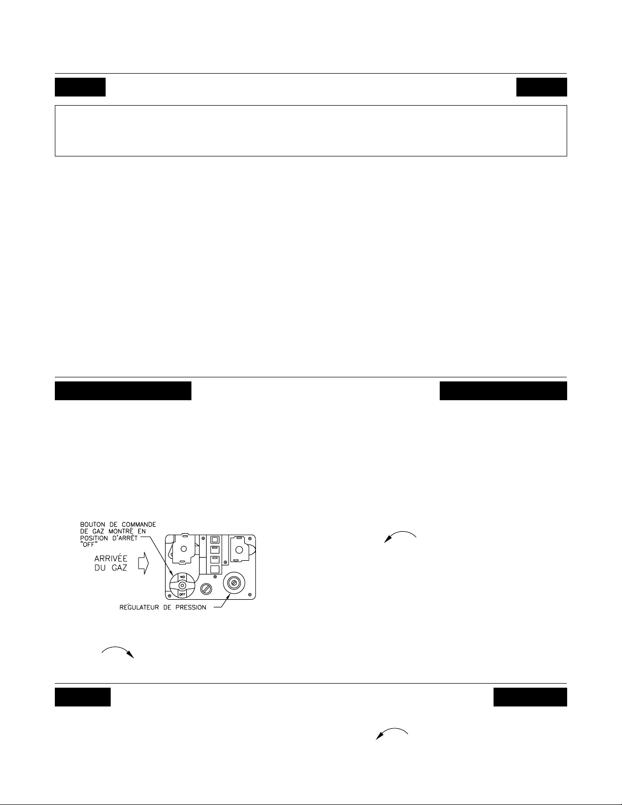
6. Tourner le bouton de commande de gaz vers la
droite , en position d'arrêt “OFF”. Ne pas
forcer!
COÙPURE DE L'ARRIVE DE GAZ A LA CHAUDIERE
1. Mette le thermostat à la température la plus basse .
2. Si un entretien doit être effectué, coupez
l'alimentation électrique de l'appareil.
3. Lever le panneau de parte du réchauffer.
8. Tourner le bouton de commande de gaz vers la
gauche , en position de marche “ON”.
9. Replacer le panneau de parte du réchauffer.
10. Rétablìr toute l'alimentation électrique de la
chaudiere.
11. Mette le thermostat thermostat sur le régleage
désiré.
12. Si l'appareil ne fonctionné pas, voir les instructions
de “COÙPURE DE L'ARRIVE DE GAZ A LA
CHAUDIERE” et appeler un technicien reparateur
ou le fournisseur de gaz.
4. Tourner le bouton de commande de gaz vers la
droite , en position d'arrêt "OFF". Ne pas
forcer!
5. Replacer le panneau de parte du réchauffer.
Page 24
Page 24 FX DIRECT VENT BOILER INSTALLATION AND OPERATION INSTRUCTIONS
BOILER SET UP
NOTE: Before starting the boiler, turn off the
electrical supply going to it. Make sure that gas is
available at the gas valve inlet. Open the valves in
the return and supply piping. Failure to take these
precautions will prevent the boiler from operation
properly.
Fill the boiler and all of the radiation with water. Make
sure that the system is completely purged of air.
Review these instructions and make sure that the boiler
installation complies with ALL of the instructions up to
this point.
BOILER OPERATION
WARNING: Before operating read and
understand the instructions contained in this
manual. Do not attempt to operate this boiler if
it has not been installed in accordance with the
guidelines set forth in this manual. Read and
fully understand the operating instructions in
the “For Your Safety Read Before Operating”
section of this manual, pg 18. Failure to comply
with this WARNING could result in a fire or
explosion!
Should overheating occur or the gas supply fail to shut
off, do not turn off or disconnect the electrical supply to
the pump. Instead, shut off the gas supply at a location
external to the appliance.
En cas de surchauffe ou si l’alimentation de gaz ne peut
être coupée, ne pas couper ni débrancher l’alimentation
électrique de la ponpe. Fermer plutôt le robinet
d’admission de gaz à l’extérieur de l’appareil..
Do not use this appliance if any part has been under
water. Immediately call a qualified service technician to
inspect the appliance and to replace any part of the
control system and any gas control that has been under
water.
N’utiliisez pas cet appareil s’il a été plongé dans l’eau,
même partiellement. Faites inspecter l’appareil par un
tecnicien qualifié et remplacez toute partie du système
de contrôle et toute commande qui ont été plongés dans
l’eau.
Direct Ignition System
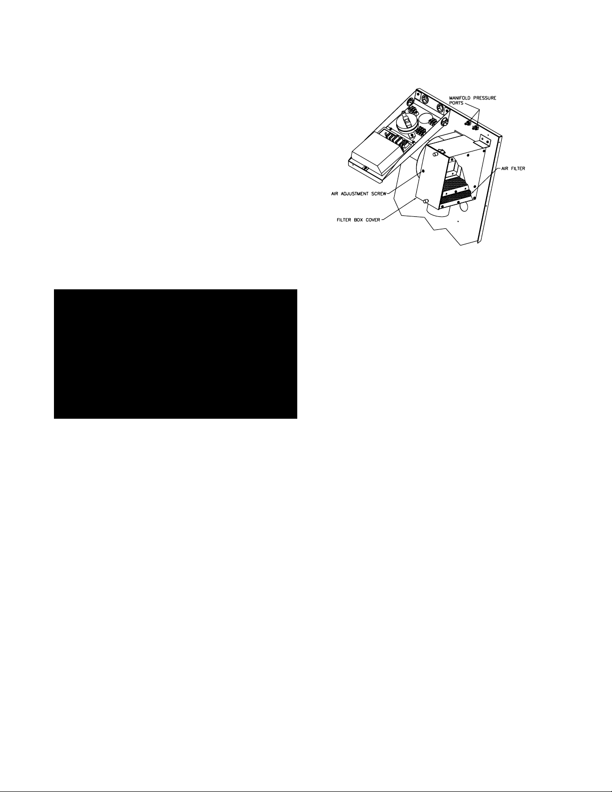
A. Connect a manometer to the pressure ports shown
in Figure 21. Make sure that the gas supply piping has
been purged of air and that all gas joints up to the gas
valve have been thoroughly checked for leaks. Wait at
least five minutes for any gas to dissipate before turning
on the electrical power.
Figure 21 - Manifold Pressure
B. Read, understand and follow the operating
instructions, on pg. 22 of this manual.
C. Raise the thermostat at least 5 degrees above the
room temperature. A delay of about 30 seconds will tak e
place as the silicon carbide ignitor heats up. Once the
ignitor is hot, the main gas valve will open and the b urner
should light. If the burner fails to light the system will
make two more ignition attempts. If the b urner lights, but
goes out within 4 seconds, the system will make three
ignition attempts. If the burner has not lit after the last
ignition try, the gas valve will close and the system will
go into lock out. DO NOT attempt to reset the system
until the ignition system has been inspected and the
problem resolved. Once the problem has been resolved
and 5 minutes have passed since the last ignition attempt,
reset the system by turning the thermostat to it's lowest
setting and then back to where it was or by momentarily
interrupting the electrical power to the boiler.
D . With the b urner in operation the manometer should
show 1.9" W .C . manifold pressure. If not, see the BOILER
CHECKING & ADJUSTMENT section below. Close the
manual shutoff valve in the gas supply line . As soon as the
burner flame goes out, open the manual shutoff valve. A
normal ignition sequence should take place.
E. With the burner in operation, interrupt the power to
the control circuit by lowering and raising the thermostat. A normal ignition sequence should follow.
F. To test the ignition safety shutoff device, close the
manual shutoff valve in the gas supply line. Within 6
seconds of main burner flame extinction, the main gas
valve solenoid should close with an audible noise. The
igniter should glow and make three attempts at ignition.
After unsuccessfully attempting to light the burner the
ignition module should lock out.
Open the manual shutoff valve in the gas supply line.
Reset the ignition control system by interrupting, then
restoring electrical power to the boiler. A normal ignition
sequence should take place.
Page 25

FX DIRECT VENT BOILER INSTALLATION AND OPERATION INSTRUCTIONS Page 25
BOILER CHECKING & ADJUSTMENT
INPUT RATE
Gas appliances are rated based on sea level operation
with no adjustment required at elevations up to 2000
feet. At elevations abov e 2000 feet, input ratings should
be reduced by 4% for each 1000 feet above sea level.
Check the input rate as follows:
NATURAL GAS:
1. Turn off all other gas appliances that use the same
gas meter as the boiler.
2. Call the gas company for the gas heating value.
3. Start the boiler and let it run for 15 minutes.
4. Using the gas meter and a stopwatch, clock the time
that it takes to burn 10 cubic feet of gas and divide
the time by 10.
5. Insert the heating value and the time, in seconds,
into the formula below.
Input Rate = Heating Value(Btu/ft3)(3600 s/hr)
Flow Rate(s/ft3)
EXAMPLE: If the heating value = 1000 Btu/ft
and the flow rate = 36 s/ft
Input Rate = (1000 Btu/ft3)(3600 s/hr)
36 s/ft
3
Input Rate = 100,000 Btu/hr
If the computed rate deviates by more than 5% from the
rated input value of the unit adjust the gas valve
pressure accordingly. DO NOT adjust the manifold
pressure by more than 5%. If a proper rate cannot be
maintained without adjusting the manifold pressure
beyond the 5% limit, the burner orifice must be replaced.
If the input rate is too low go to the next larger size
orifice. if the input r ate is too high, go to the next smaller
size orifice.
3
3
PROPANE GAS:
The input rate for LP units is factor y set based on the
orifice size. The manifold pressure must be set at 1.9"
W.C. and the orifice supplied with the boiler used unless
the unit is to be derated for altitude.
CAUTION: Never increase the input to the boiler
above that for which it is rated. Doing so can cause
premature failure of the boiler!
GAS PRESSURE ADJUSTMENT
NATURAL GAS:
Optimum results are obtained when the boiler is
operated at its full input rating, with 1.9" W.C. of manifold
pressure. The manifold pressure should not be more that
5% off this value. The gas valve pressure regulator has
been preset at the factory. If adjustment is necessary
the following steps must be followed:
1. Connect each side of a manometer to the two
pressure ports shown in Figure 21 to obtain the
manifold pressure.
2. Connect a flue gas analyzer to the vent pipe.
3. Rotate the regulator adjustment screw clockwise to
increase the manifold pressure, counterclockwise to
decrease it. Never force the regulator adjustment
screw or the gas valve will be damaged!
4. The CO2 reading should fall between 7% and 9%
with a CO reading of less than 50 ppm air free.
5. Adjust the air damper using the screw on the front
of the filter box if the CO2 and CO readings are not
within the range given in step 4.
6. Recheck the manifold pressure and adjust it if
necessary.
7. Replace the regulator adjustment screw cap and
pressure port caps once the boiler is properly set
up.
PROPANE GAS:
A manifold pressure of 1.9" W.C. must be maintained
for proper operation of the boiler. If the manifold pressure
is off by more than 5% or if the CO2 and CO readings
are not within the range specified in step 4 above, adjust
it according to steps 1 through 7 above.
Page 26
Page 26 FX DIRECT VENT BOILER INSTALLATION AND OPERATION INSTRUCTIONS
Main Burner Flame
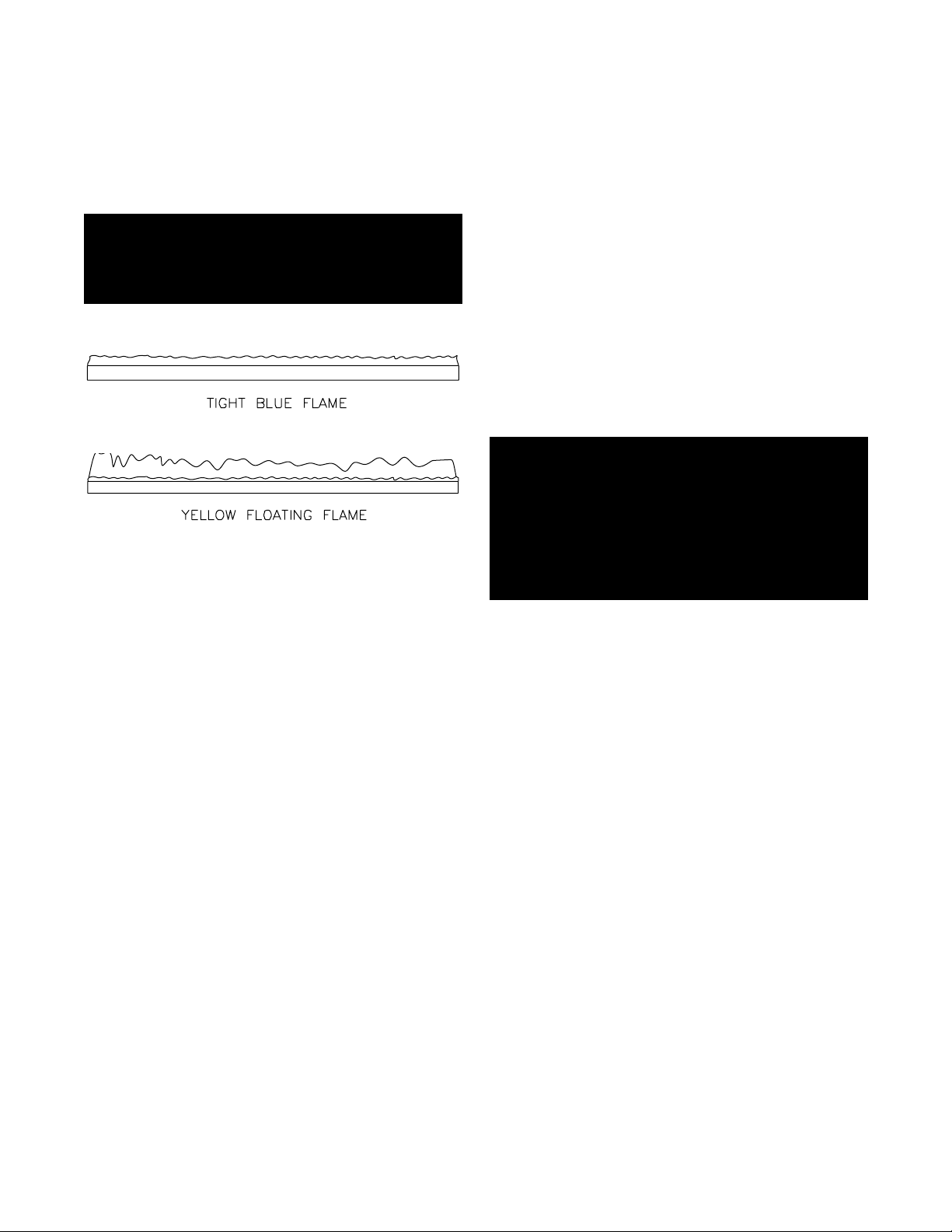
A properly adjusted main burner flame will produce a
tight blue flame pattern about 1/2 inch tall from the
burner’s surface, Figure 22. A yellow floating or tall
stringy flame is not normal and must be corrected.
WARNING: Yellow, floating flames indicate a lack
of combustion air. DO NOT operate the boiler
until the problem is solved or severe personal
injury or death may occur!
Figure 22 - Burner Flame
Thermostat Adjustment
Set the heat anticipator to 1.1 amps when controlling
the boiler directly. For zoned systems set the heat
anticipator to match the amp draw of the zone valves
or pump relays.
BOILER MAINTENANCE
The boiler should be cleaned and inspected once a year ,
before each heating season. Refer to Figures 21 for
component identification
CAUTION: Servicing, inspection and adjustment
must be done by a trained technician in accordance
with all applicable local and national codes.
Improper servicing or adjustment could damage the
boiler!
Control Panel
Use a soft brush and/or a vacuum cleaner to ensure that
the electrical components are free from dust or deposits
that would impair the boiler's performance.
Air Filter
1. Remove the front jacket panel.
2. Remove the filter box cover and filter.
3. Wash the filter in warm water. Shake out all excess
moisture before reinstalling.
Burner Box Removal & Replacement
CAUTION: The burner box should not be removed
unless there is a problem with it or the boiler is
being converted for a different type of gas. Careless
handling can damage the burner!
WARNING: The ceramic combusiton chamber in
the burner box and its gasket contain crystalline
silica. Wear a tightly fitted dust mask when
servicing the burner and gently handle the
burner and its gasket to prevent inhalation of
airborne fibers. Crystalline silica fibers have
been identified as carcinogenic, or possibly
carcinogenic when inhaled.
1. Close the manual shutoff valve in the gas supply
line and turn off electrical power to the boiler.
2. Lift off the front & top jacket panels.
4. Disconnect the wires going to the igniter, flame rod,
ground rod and thermal switch.
5. Release the eight hold-down latches, page 28.
6. Slightly lift and slide the burner towards that back
of the boiler.
7. Gently lift the burner out of the boiler.
8. Install the factory assembled replacement burner
box and the new gasket.
9. Engage the eight hold-down latches and reconnect
all of the wires.
10. Confirm proper operation of the boiler.
11 Replace the jacket panels.
Page 27

FX DIRECT VENT BOILER INSTALLATION AND OPERATION INSTRUCTIONS Page 27
Heat Exchanger Cleaning
In the unlikely event that the heat exchanger becomes
blocked consult the factory for the proper cleaning
procedure.
Condensate System
Ensure that the condensate removal system is sound
and working properly.
Vent System
The entire vent system must be thoroughly inspected
for any signs of blockage, corrosion or leaks.
Immediately replace any unsound vent system piping.
Remove any foreign matter in or near the vent terminal
or around the boiler that might obstruct the flue of
combustion and ventilation air.
Blower Motor
Every 3 to 6 months, lubricate the inducer motor using
2 drops of 20W non detergent motor oil in each oil port.
Low Water Cutoff
If the boiler has been equipped with a low water cutoff device, follow the manufacturer's instructions for
cleaning and to confirm proper operation
Relief Valve
The relief valve should vent water when the test lever
is lifted. It should not w eep or discharge water at normal
system pressure. NEVER try to clean or repair the relief
valve! If the valve fails replace it!
Aquastat High Limit
The aquastat high limit controls the maximum water
temperature in the boiler. It is adjustable from 140°F
(60°C) to 220°F (104°C). If the water temperature
reaches the set temperature before the demand f or heat
has been met, the aquastat high limit should shut the
burners off. The outlet water temperature should never
exceed 220°F (104°C). If the aquastat high limit fails to
function properly replace it.
Page 28
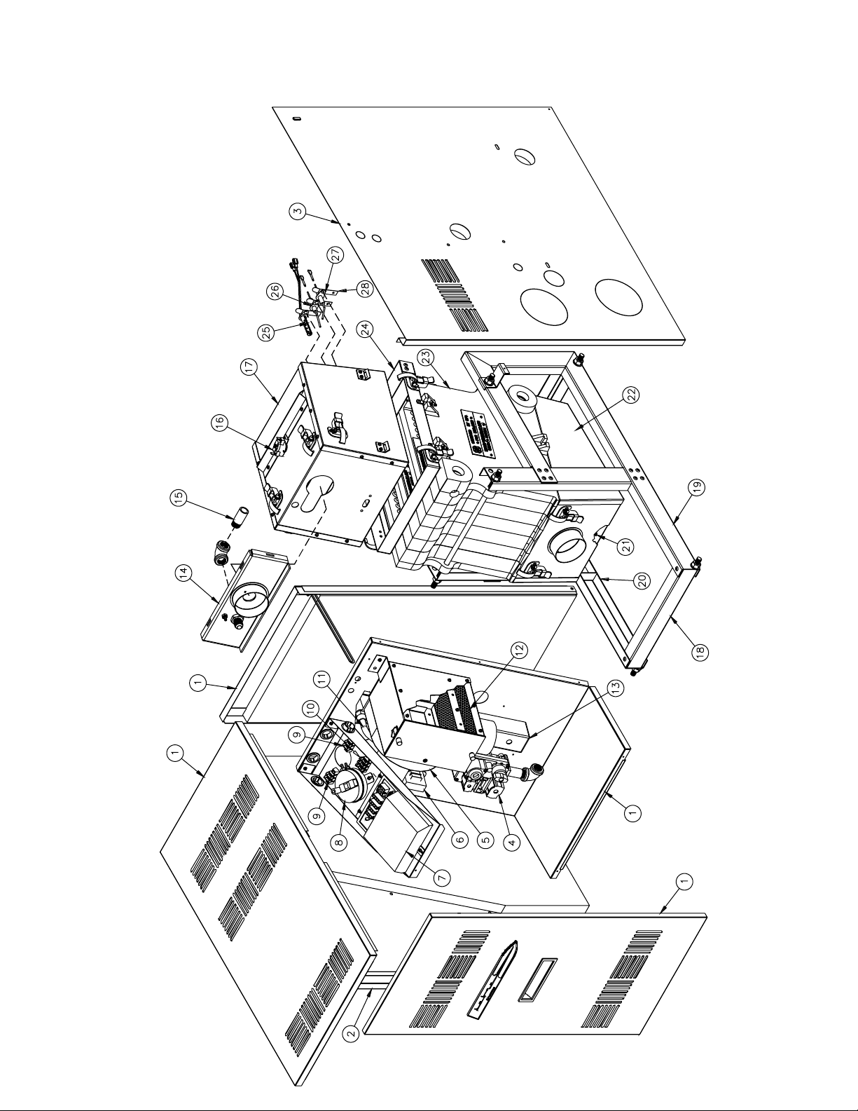
Page 28 FX DIRECT VENT BOILER INSTALLATION AND OPERATION INSTRUCTIONS
Page 29
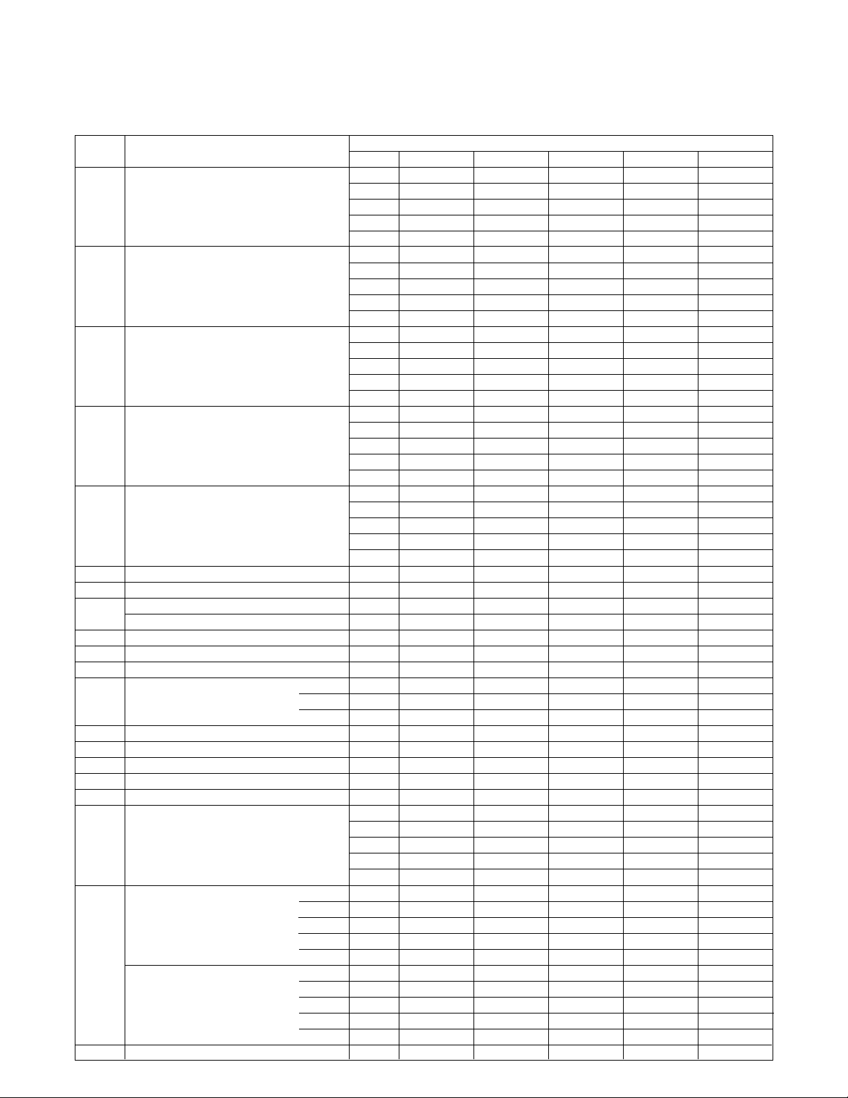
FX DIRECT VENT BOILER INSTALLATION AND OPERATION INSTRUCTIONS Page 29
SERVICE AND REPLACEMENT PARTS LIST
Model Size with Item Quantities Below
Ref # Name of Part
1 Jacket Panel Set BM-8610 1
1a Front Panel 03-1552 1
1b Rear Panel 03-1557 1
1c Top Panel 03-1562 1
1d Inner Front Panel 03-1567 1
2 Left Jacket Side Panel 03-1551 11111
3 Right Side Panel 03-1550 11111
4 Gas Valve, White Rodgers 36E65 02-1567 1 1 1
Gas Valve, White Rodgers 36D27 02-1568 1 1
5 Blower, Fasco 702110816 58-1849 11111
6
Transformer, Honeywell AT140B-1016, 40 VA
7 Ignition Control 02-4129 11111
8 Pressure Switch .45 WC 02-4878 1 1 1
.49 WC 02-4879 1
.54 WC 02-4880 1
9 Terminal Strip, 2 Position 58-2298 22222
10 Terminal Strip, 3 Position 58-2299 11111
11 Gas T ube BM-8642 11111
12 Filter 60-4298 11111
13 Limit Control, Honeywell L4008A-1015 02-3210 11111
14 Blower Mounting Plate Assembly BM-8630 1
15 Main Gas Orifice, Natural 0.182 25-0051 1
0.234 25-0053 1
0.265 25-0054 1
0.323 25-0055 1
0.375 25-0056 1
Main Gas Orifice, LP 0.144 25-0050 1
0.182 25-0051 1
0.209 25-0052 1
0.234 25-0053 1
0.265 25-0054 1
16 Thermal Switch 58-2542 11111
Part # 70 105 140 175 210
BM-8611 1
BM-8612 1
BM-8613 1
BM-8614 1
03-1553 1
03-1554 1
03-1555 1
03-1556 1
03-1558 1
03-1559 1
03-1560 1
03-1561 1
03-1563 1
03-1564 1
03-1565 1
03-1566 1
03-1568 1
03-1569 1
03-1570 1
03-1571 1
26-3206 11111
BM-8631 1
BM-8632 1
BM-8633 1
BM-8634 1
Page 30
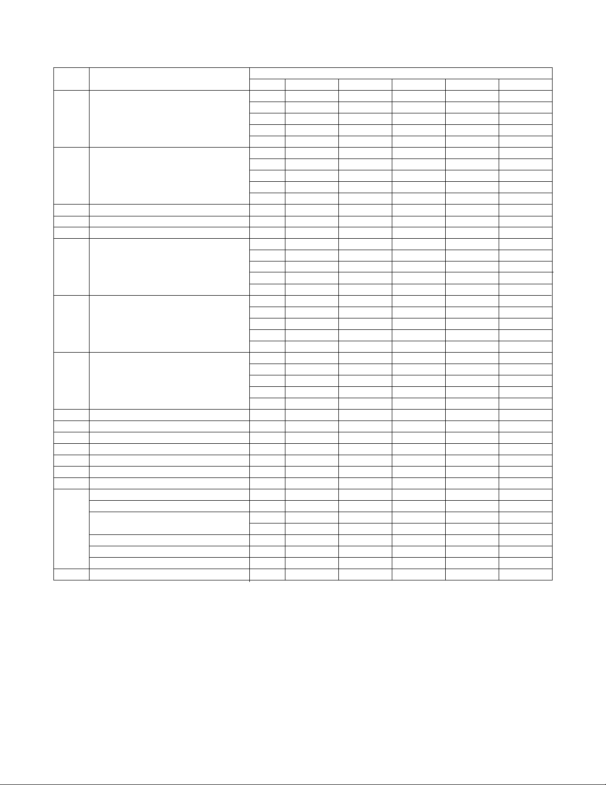
Page 30 FX DIRECT VENT BOILER INSTALLATION AND OPERATION INSTRUCTIONS
Model Size with Item Quantities Below
Ref # Name of Part
17 Burner Box Assembly BM-8625 1
18 Frame Cross Members 04-1579 2
19 Right Base Frame Assembly BM-8640 11111
20 Left Base Frame Assembly BM-8641 11111
21 Flue Collector Drain Fitting 60-4299 11111
22 Flue Collector BM-8635 1
23 Block Assembly BM-8615 1
24 Burner Box Frame Assembly BM-8620 1
25 Igniter, Norton 601XBM 04-1339 11111
26 Flame Rod, PSE ME7 G 04-1340 11111
27 Ground Rod, PSE ME8 GS1 04-1341 11111
28 Ingiter, Flame & Ground Rod Spring Clip 57-5222 33333
N/S Ingiter, Flame & Ground Rod Gasket 59-1050 11111
N/S Relief Valv e 22-1203 11111
N/S Temperature & Pressure Gauge 20-1019 11111
See Transformer Primary Harness, P1 BM-8643 11111
Fig. Transformer Secondary Harness, P2 BM-8644 11111
20A Control Harness, P3 BM-8645 1 1 1
Circulator Harness, P4 BM-8647 11111
HSI Harness, P6 BM-8648 11111
L1, L2 Harness, P7 BM-8649 11111
N/S Jacket Polish, 4 oz. Bottle 70-3398 11111
Part # 70 105 140 175 210
BM-8626 1
BM-8627 1
BM-8628 1
BM-8629 1
04-1580 2
04-1581 2
04-1582 2
04-1583 2
BM-8636 1
BM-8637 1
BM-8638 1
BM-8639 1
BM-8616 1
BM-8617 1
BM-8618 1
BM-8619 1
BM-8621 1
BM-8622 1
BM-8623 1
BM-8624 1
BM-8646 1 1
Page 31

FX DIRECT VENT BOILER INSTALLATION AND OPERATION INSTRUCTIONS Page 31
INSTRUCTIONS T O THE INST ALLER
The INSTALLER must give this copy of the INSTALLATION AND OPERATING INSTRUCTIONS to the
boiler owner and make sure that the owner or operator
has a basic understanding of the following:
1. The operating instructions, the type of ignition
system installed and how it operates.
2. What the labels on the boiler say.
3. How to start up and shut off the boiler.
4. How to turn the gas and electrical power on or off.
5. What to do if the boiler ignition system locks out.
6. Where to check the system temperature and
pressure and what they should be.
7. The importance of reading, understanding and
following these instructions.
8. The importance of visually inspecting the vent
system on a monthly basis.
The INSTALLER MUST make sure that the owner
knows to shut the boiler off and call for service if the
following conditions occur:
1. Yellow lazy flames or flames outside the jacket.
2. Gas smell or other strange odors.
3. Discoloration of the boiler or surrounding materials.
4. Water leaking from the heating system piping or
relief valve.
5. Flue products leaking from the vent system into the
living space. Dampness or condensation in the
building is a good indicator of this condition.
6. The boiler's flame rollout safety system is actuated.
7. Control malfunction or sporadic operation.
Any appliance that burns natural gas, propane gas, fuel
oil, wood or coal is capable of producing carbon
monoxide (CO). Carbon Monoxide (CO) is a gas, which
is odorless, colorless and tasteless but is very toxic. If
your Hydrotherm boiler is not working properly, or is not
vented properly, dangerous levels of CO may
accumulate. CO is lighter than air and thus may travel
throughout the building.
Symptoms of CO poisoning include the following:
Dizziness, vision problems, shortness of breath,
headaches, loss of muscle control, unclear thinking,
nausea, weakness and unconsciousness.
The symptoms of CO poisoning are often confused with
those of influenza, and the highest incidence of
poisoning occurs at the onset of cold weather or during
flu season. A victim may not experience any symptoms,
only one symptom, or a few symptoms. Suspect the
presence of carbon monoxide if symptoms tend to
disappear when you leave your home.
The following signs ma y indicate the presence of carbon
monoxide:
• Hot gases from appliance, venting system, pipes or
chimney, escaping into the living space.
• Flames coming out around the appliance.
• Yellow colored flames in the appliance.
• Stale or smelly air.
• The presence of soot or carbon in or around the
appliance.
• Very high unexplained humidity inside the building.
If any of the symptoms of CO poisoning occur, or if any
of the signs of carbon monoxide are present, VACATE
THE PREMISES IMMEDIATELY AND CONTACT A
QUALIFIED HEATING SERVICE COMPANY OR THE
GAS COMPANY OR THE FIRE DEPARTMENT!
WARNING: Improper installation, adjustment,
alteration, service or maintenance can cause
property damage, personal injury exposure to
hazardous materials or loss of life. Installation
and service must be performed by a qualified
installer. service agency or the gas supplier who
must read and follow the supplied instructions
before installing, servicing or removing this
boiler, This boiler contains crystalline silica
materials that have been identified as
carcinogenic or possibly carcinogenic to
humans when inhaled.
BRIEF EXPOSURE TO HIGH CONCENTRATIONS OF
CO, OR PROLONGED EXPOSURE TO LESSER
AMOUNTS OF CO MAY RESULT IN CARBON MONOXIDE POISONING! EXPOSURE CAN BE FATAL
AND EXPOSURE TO HIGH CONCENTRATIONS MAY
RESULT IN THE SUDDEN ONSET OF SYMPTOMS
INCLUDING UNCONSCIOUSNESS.
AVERTISSEMNET: Une installation, un réglage,
une modification, une réparation ou un entretien
non comforme aux normes peut entraîner des
dommages matériels, des blessures exposition
à des matières dangereuses ou la mort.
L'installation et l'entretien doivent être effectués
par un installateur ou un service d'entretien
qualifié ou le fournisseur de gaz qui doivent
avoir lu les instructions fournies avant de faire
l'installation, l'entretien ou l'enlèvement de la
chaudière et les respecter, Cette chaudière
contient des matériaux qui ont été identifiés
comme étant cancérogènes ou pouvant l' être.
Page 32

IN UNITED STATES: 260 NORTH ELM ST. • WESTFIELD, MA 01085 • (413) 564-5515 • FAX (413) 568-9613
IN CANADA: 5211 CREEKBANK RD. • MISSISSAUGA, ONT. L4W 1R3 • (905) 625-2991 • FAX (905) 625-6610
www.hydrotherm.com
 Loading...