

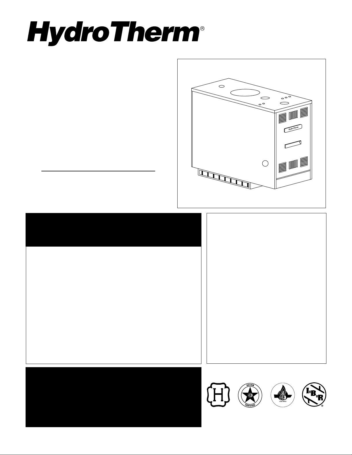
HydroTherm EW-65, EW-85, EW-100, EW-125, EW-145 Installation, Operation & Maintanance Manual
...Page 1
EW2-1203
42-9510
IN UNITED STATES: 260 NORTH ELM ST. • WESTFIELD, MA 01085 • (413) 564-5515 • FAX (413) 568-9613
IN CANADA: 5211 CREEKBANK RD. • MISSISSAUGA, ONT. L4W 1R3 • (905) 625-2991 • FAX (905) 625-6610
MODEL EW
SERIES
INSTALLATION,
OPERATION
& MAINTENANCE
MANUAL
Gas-Fired Water Cast Iron Boilers
65,000 to 165,000 Btuh Input
WARNING: If the information in this manual is not
followed exactl y, a fire or explosion may result causing
property damage, personal injury or loss of life.
Do not store or use gasoline or other flammable
vapors and liquids in the vicinity of this or any
other appliance.
WHAT TO DO IF YOU SMELL GAS:
• Do not try to light any appliance.
• Do not touch any electrical s witch. Do not use an y
phone in your building.
• Immediately call your gas supplier from a
neighbor’s phone. Follow the gas supplier’s
instructions.
• If you cannot reach your gas supplier, call the
fire department.
Installation and service must be performed by a
qualified installer , service agency or the gas supplier .
BOILER INSTALLATION
Introduction.............................................. 2
Step 1: Locating & Setting Boiler............. 4
Step 2: Installing/Purging Water Piping... 5
Step 3: Venting Boiler............................... 8
Step 4: Installing/Testing Gas Piping........ 10
Step 5: Wiring Boiler................................ 12
START-UP & OPERATION
Safety Controls........................................ 15
Start-Up & Adjustments........................... 15
MAINTENANCE
Water Treatment...................................... 18
Freeze Protection..................................... 18
Before Each Heating Season.................. 18
How To Change Orifices........................... 19
Troubleshooting....................................... 19
Appendix A
(French Vent Damper Translation)........... 20
WARNING: Installation and service must be
performed by a qualified installer, service agency
or the gas supplier in accordance with all local
and national codes. Failure to comply with this
warning can result in a fire or explosion causing
property damage, personal injury or loss of life!
Page 2

2
CAUTION: Indicates a imminently hazardous situation which, if not avoided, may result in minor
injury or property damage.
The following terms are used throughout this manual to bring attention to the presence of potential hazards
or to important information concerning the product:
DANGER: Indicates an imminently hazardous situation which, if not avoided, will result in death,
serious injury or substantial property damage.
WARNING: Indicates a imminently hazardous situation which, if not avoided, could result in
death, serious injury or substantial property
damage.
NOTE: Used to notify of special instructions on
installation, operation or maintenance which are
important to equipment but not related to personal
injury hazards.
AVERTISSMENT. Assurez-vous de bien suivre les instructions données dans cette
notice pour réduire au minimum le risque d’incendie ou d’explosion ou pour éviter tout
dommoge matériel, toute blessure ou la mort
Ne pas entreposer ni utiliser d’essence ou ni d’autres vapeurs ou liquides inflammab les à pro xim-
ité de cet appareil ou de tout autre appareil.
QUE FAIRE SI VOUS SENTEZ UNE ODEUR DE GAZ:
• Ne pas tenter d’allumer d’appareil.
• Ne touchez à aucun interrupteur; ne pas vous servir des téléphones se trouvant dans
le bâtiment.
• Appelez immédiatement votre fournisseur de gas depuis un voisin. Suivez les intruc-
tions du fournisseur.
• Si v ous ne purvez rejoindre le fournisseur, appelez le service des incendies.
L’installation et l’entretien doivent être assurés par un installateur ou un service
d’entretien qualifié ou par le fournisseur de gaz.
Page 3
3
ANSI/ASME CODE COMPLIANCE: Installation must
conform to requirements of authority having jurisdiction
or, in absence of such requirements, to National Fuel
Gas Code ANSI Z223.1-latest edition and to National
Electric Code NFPA-70-latest edition. Where required by
authority having jurisdiction, installation must also conform to Standard for Controls and Safety Devices for
Automatically Fired Boilers, ANSI/ASME CSD-1.
For Canada, the installation must be in accordance with
Standards CAN/CGA-B149 (.1 or .2) Installation Codes
for Gas Burning Appliances and Equipment and with
Standard C.S.A. C22.1 Canadian Electrical Code, Part 1
and Part 2, and/or local codes.
In the Commonwealthof Massachusetts, the installation
must be performed by a licensed plumber or gas fitter.
.
BOILER SHIPMENT: Each boiler is shipped in a single
carton. There is a vent damper packed separately with
the boiler.
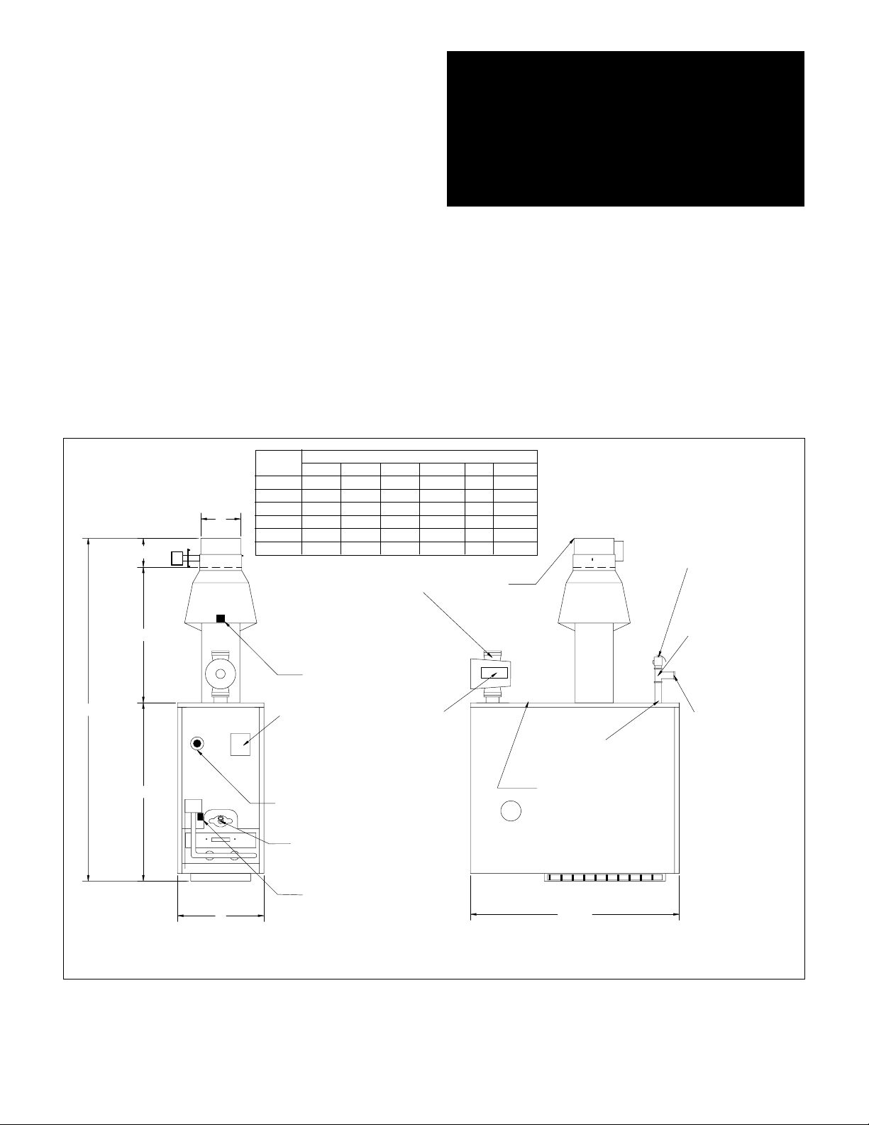
MODEL EW BOILER DIMENSIONS
WARNING: Installers must follow local regulations
with respect to the installation of CO detectors and
follow the manufacturer's stated maintenance
schedule for this boiler!
ATTENTION: Observer les règlements règional à
l'egard des détecteurs de monoxyde de carbone et
observer entretien de manufacturier pour cette
chaudière!
BOILER
MODEL
EW-65
EW-85
E
F
C
D
A
EW-100
EW-125
EW-145
EW-165
A
24-3/4"
27-1/2"
27-1/2"
27-1/2"
31"
31"
SPILL SWITCH
HI-LIMIT AQUASTAT
TEMP./PRESS.
INDICATOR
DRAIN
VALVE
B
13-1/8"
13-1/8"
13-1/8"
13-1/8"
13-1/8"
13-1/8"
DIMENSIONS
C
14-1/4"
45-1/16"
14-3/4"
48-5/16"
14-3/4"
48-5/16"
19"
31"
30-1/16"
1-1/4"
RETURN
CIRCULATOR
(PACKAGED
BOILERS)
D
53"
68-1/2"
68-1/8"
VENT DAMPER
F
E
5"
6-1/16"
6-1/16"
5"
5"
6-1/16"
6-1/2"
6"
6-1/2"
6"
7-1/16"
7"
PRESS./RELIEF
VALVE
EW-85, 100, 125
AIR ELIMINATION
TAPPING
EXPANSION TANK
TAPPING
1-1/2" SUPPLY
EW-65, 145, 165
1-1/2" SUPPLY
EW-85, 100, 125
PRESS./RELEF VALVE
EW-65, 145, 165
ROLLOUT
B
SWITCH
32-1/2"
Page 4
4
BOILER INSTALLATION
STEP 1: LOCATING & SETTING THE BOILER
PROCEDURE A: Check that provisions for combustion air are in accordance with National Fuel Gas Code
ANSI Z223.1-latest edition and all applicable local codes.
In Canada, follow CAN/CGA B149(0.1 or .2) installation codes.
If boiler is installed in an unconfined space, ade-
quate air will be available via normal infiltration.
If boiler is installed in a confined space, a space
with a volume of less than 50 cubic feet per 1000
Btu/hr of gas input for all fuel burning equipment, or
building construction is unusually tight, adequate air
for combustion must be provided by two openings:
one located about 6" below the ceiling, the other about
6" above the floor. When communicating directly with
the outside, each opening must have a minimum free
area of one square inch per 4000 Btu/hr of gas input.
When ventilation air is provided by openings in doors,
etc. to adjoining spaces having adequate infiltration,
each opening must have a minimum free area of one
square inch per 1000 Btu/hr of gas input.
NOTE: Boiler employs atmospheric combustion.
Combustion air must not be contaminated with
halogenated hydrocarbon vapors, aerosol propellants or freon; otherwise, heat exchanger will be
subject to corrosion, reducing boiler life.
WARNING: This boiler must be supplied with
combustion air in accordance with Section 5.3,
Air for Combustion & Ventilation, of the latest edition of the National Fuel Gas Code, ANSI Z223.1
and all applicable local building codes. Failure to
provide adequate combustion air for this appliance can result in excessive levels of carbon
monoxide which can result in severe personal
injury or death!
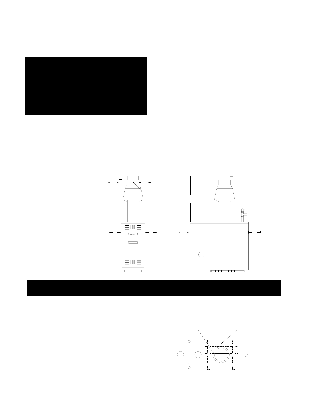
FIGURE 1.1
PROCEDURE B: Check
minimum clearances
to combustibles are
proper as shown.
Local requirements
may specify greater
clearances & must be
adhered to.
Boiler shall be install-
ed such that the gas
ignition system com-
ponents are protected
from water, dripping,
spraying, rain, etc.,
during appliance oper-
ation and service, cir-
culator replacement,
condensate trap, con-
trol replacement, etc.
WARNING: Never install boiler on combustible flooring without combustible flooring pan or on carpeting
as heat damage and/or fire may result.
CAUTION: Do not loosen tie rods on absorption unit. They accommodate thermal expansion. Loss of
boiler structural integrity and water leaks/damage may result.
PROCEDURE C: Check component positioning.
1. Remove all packing material from boiler.
2. Check that burners and controls are in the proper position.
3. Check proper seating of baffle grid or baffle inside of dome
opening (see Figure 1.2).
DOME
BAFFLE GRID
FIGURE 1.2
➤
➤
➤
CAUTION: Locate boiler so horizontal connecting flue pipe is as short as possible. Maximize height of
vertical flue connector.
6"
6"
VENT
DAMPER
TOP
48"
LEFT RIGHT
6"
FRONT
VIEW
6"
RECOMMEND
MORE FOR
ACCESS TO
VENT
DAMPER
POSITION
INDICATOR
FRONT
CLOSET
6"
SIDE
VIEW
REAR
6"
Page 5
5
STEP 2: INSTALLING & PURGING WATER PIPING
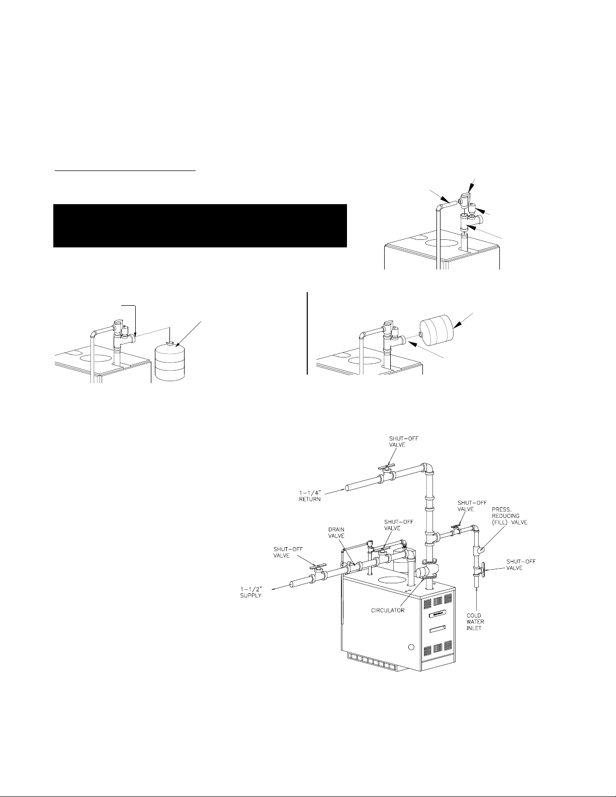
PROCEDURE B: Install supply and
return water piping. For Models
EW-85, 100 & 125, supply outlet is
on top-front of boiler and vent
fitting assembly tapping is at toprear of boiler, Figure 1.4.
If boiler is installed above level of
radiation, a low water cut-off must
be used.
NOTE: ALL EXTERNAL PIPING
MUST BE SUPPORTED BY HANGERS, NOT BY BOILER OR ACCESSORIES.
CAUTION: To prevent damage due
to excessive condensation, one of
the following piping options should
be used, see next page.
FIGURE 1.4
CAUTION: Boiler must not be used without forced circulation, as overheating or failure of cast iron sections
may result.
PROCEDURE A: Install vent tapping assembly, components and relief valve discharge piping. For Models
EW-85, 100 & 125, supply outlet is on the top front of the boiler and vent fitting assembly
tapping is at top-rear of boiler.
Relief Valve Discharge Piping: Must terminate 6" above floor &
be same size or larger than valve outlet, Figure 1.3.
FIGURE 1.3
WARNING: No valve of any type may be installed between
the boiler and relief valve or an explosion from over-pressure may occur.
➤
➤
CAUTION: Piping must be installed from relief valve discharge so there will be no danger of scalding personnel.
/2" NPT TAPPING
VERTICAL EXPANSION TANK
ARRANGEMENT (PREFERRED)
MAY BE PIPED TO
EITHER SIDE OF BOILER
PRESS. RELIEF
VALVE
RELIEF VALVE
DISCHARGE
PIPING
AIR VENT
VENT
FITTING
ASS'Y.
HORIZONTAL EXPANSION
TANK ARRANGEMENT
MAY BE SCREWED
INTO TAPPING
Page 6
6
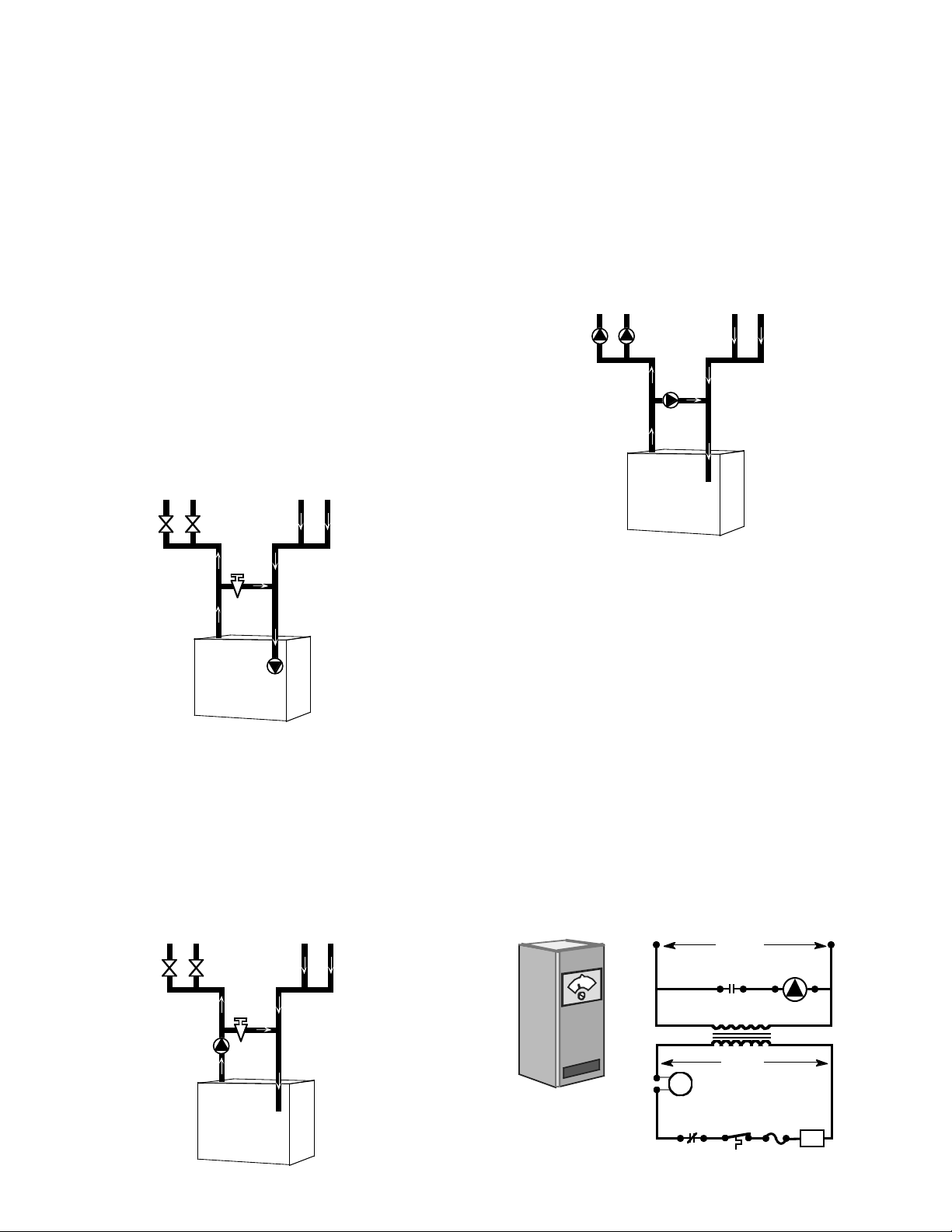
SYSTEM BYPASS
For systems using a circulator on the return as either a
single zone, or multiple zones with zone valves, install a
system bypass line between the supply and return on
the suction side of the circulator (see Fig 1.5). Install a
metering valve in this bypass line to regulate the amount
of flow that will be diverted to the return. A plug valve
offers the best control for this application. Although other
valves may be less expensive, a plug valve will be easier
to set accurately.
In the absence of a flow indicator, set the metering valve
using temperature as a guide. The accompanying diagram suggests one scenario. This addition requires only
two tees, a plug valve, and a small amount of pipe and
offers the simplest approach to reliably controling condensation. For this system and those that follow, be
aware that you are using a percentage of the pump
capacity to blend, but the friction loss for the entire
pump flow has been reduced. In most cases, the standard pump packaged with the boiler has enough capacity to feed the baseboard distribution system and the
bypass line.
PUMP AWAY BYPASS
For systems that use a single circulator to pump away
from the boiler, the bypass should be installed on the
discharge side of the circulator (see Fig. 1.6). Full temperature water supplies the baseboard distribution system as before. Half of the circulator’s volume moves
through the bypass, blending and heating the cooler
return water. Again, the cost of installing the bypass is
small and setting it by temperature can be accomplished
with a contact thermometer.
PUMPED BLEND
An additional circulator can also be used to provide a
return water temperature blend. This method works well
with systems with multiple zones with circulators (see
Fig. 1.7). The dedicated bypass circulator provides a
strong blending flow without diminishing the flow available to any heating zone. Any residentially sized circulator is adequate for this purpose.
Each of these bypass solutions also has the added benefit of increasing circulation in the boiler which will maximize tankless coil output and increase the accuracy of
temperature sensing controls.
REVERSE ACTING AQUASTATS
An alternative for existing systems experiencing condensation that does not require re-piping the boiler utilizes a
reverse acting aquastat, one that makes on temperature
rise. This approach works best in single zone systems.
Wired in series with the circulator, this control holds the
circulator off until the boiler reaches an acceptable temperature and then starts system circulation (see Fig.
1.8).
The most commonly available reverse acting aquastat is
a Honeywell L4006B. The aquastat should be mounted
in an immersion well directly installed in the boiler. The
use of heat conductive grease (Honeywell part
# 972545) in the immersion well is strongly recommended for fast and accurate temperature response. Set this
adjustable aquastat to make at no less than 130° F.
While this method can cause the circulator to cycle
more frequently, setting the aquastat’s differential to the
maximum (25-30°F) will minimize short cycling.
FIGURE 1.5
FIGURE 1.7
FIGURE 1.8
FIGURE 1.6
SUPPLY
RETURN
100%
160° F
200%
160° F
SUPPLY
100%
160° F
PUMPED
BYPASS
RETURN
100%
120° F
200%
140° F
FIGURE 1.7
50%
50%
120° F
100%
140° F
FIGURE 1.5
50%
160° F
100%
160° F
160° F
SYSTEM
BYPASS
SUPPLY
50%
160° F
100%
160° F
PUMP AWAY
50%
160° F
BYPASS
RETURN
50%
120° F
100%
140° F
FIGURE 1.6
115 volts
reverse
aquastat
REVERSE
AQUASTAT
SET AT 120° F
N.O.
24 volts
T
t'stat
T
operating
aquastat
N.C.
circulator
GV
FIGURE 1.8
Page 7
7
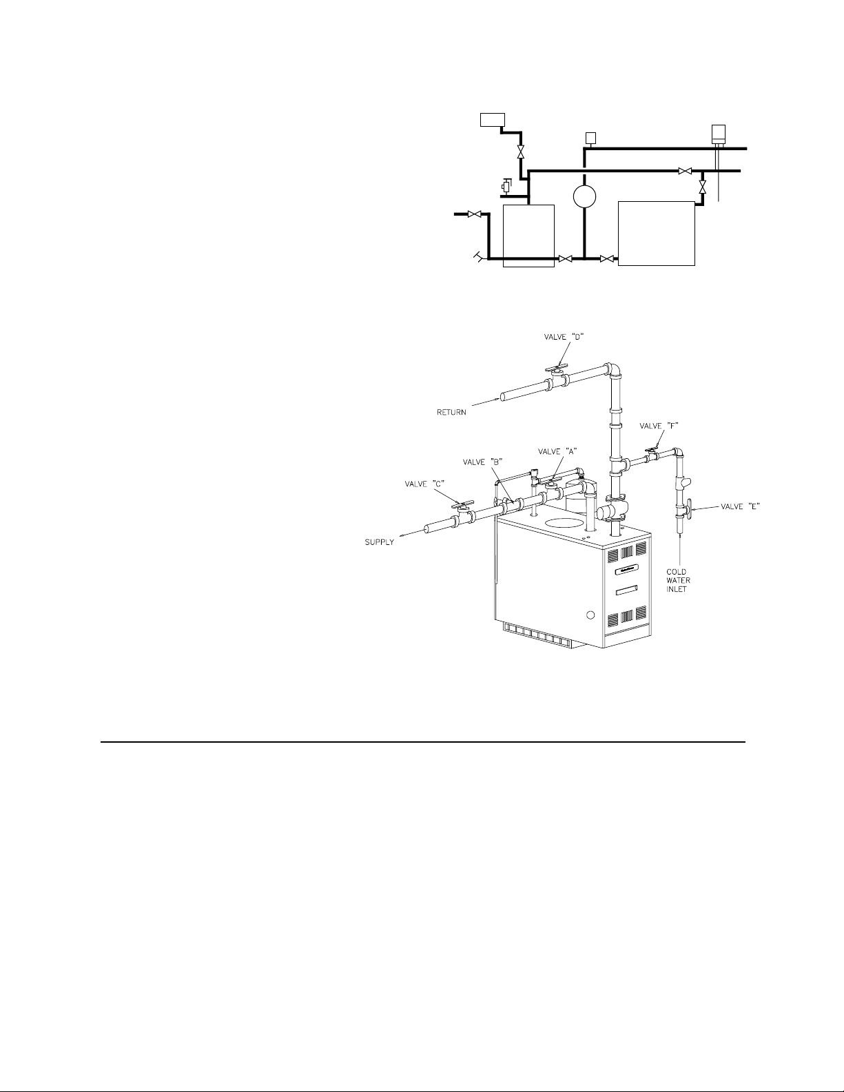
PROCEDURE D: Completely fill & purge
heating system. Make sure that all heating system manual air vents are closed.
1. Check that flow direction arrows on
hydronic components are facing in proper
direction.
2. Attach hose to drain valve “B”, Figure
1.10, and close valve “A”. Open valves “C”,
“D”, “E” and “F” and drain valve “B”. Fill
system with water until water runs out of
the hose in a steady stream, no visible air
bubbles.
3. Close valves “C” and “D”. Open valve
“A”. When water runs out of the hose in a
steady stream, no visible air bubbles, close
drain valve “B”.
FIGURE 1.10
If a hot water boiler is installed in connection with a
water chiller, the chilled water must be piped in parallel with the boiler, using appropriate valves to prevent
the chilled medium from entering the boiler, Figure
1.9. When boilers are connected to heating coils located in air handling units where they may be exposed to
refrigerated air circulation, the boiler piping system
shall be equipped with flow-control valves or other
automatic means to prevent gravity circulation of the
boiler water during the cooling cycle.
PROCEDURE C: For combination heating and cooling installations only.
FIGURE 1.9
➤
➤
FOR WATER TREATMENT & FREEZE PROTECTION REQUIREMENTS,
SEE “ MAINTENANCE” IN THIS MANUAL
RELIEF
VALVE
FILL
VALVE
DRAIN
NOTE: VALVES "H" OPENED ON HEATING WITH "C" VALVES
CLOSED REVERSE PROCEDURE ON COOLING.
EXP. TANK
BOILER
BOILER
H
VENT
PUMP
C
CHILLER
H
C
DRAIN
ROOM
UNIT
Page 8
8
STEP 3: VENTING THE BOILER
DANGER: Draft hood and vent outlet must not be altered, as proper operation would be jeopardized; flame
rollout, fire or carbon monoxide poisoning will result.
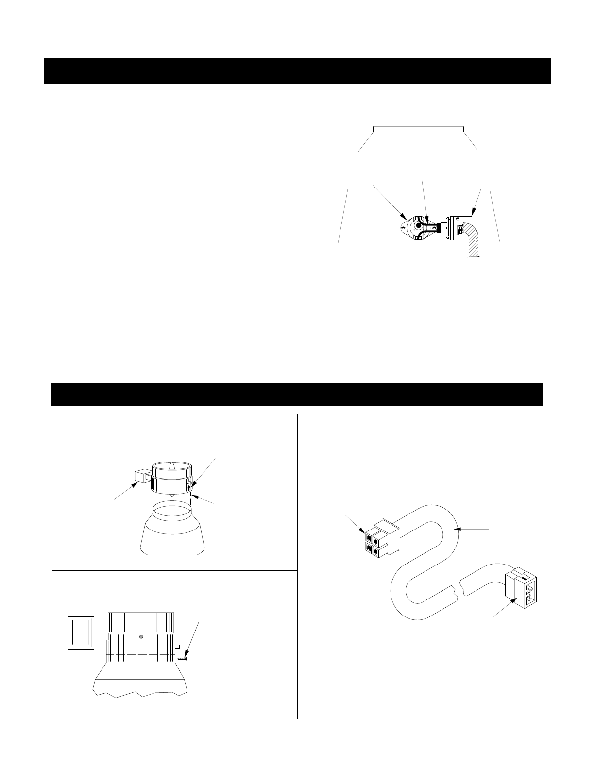
PROCEDURE B: Install vent damper. (For French version, see Appendix A at rear of manual.)
1. Mount damper on top of draft hood.
FIGURE 1.12
2. Secure damper to draft hood.
FIGURE 1.13
3. Connect wire harness.
FIGURE 1.14
DANGER: Only the boiler may be served by the vent damper. Do not use it to vent an additional appliance;
this will cause fire or carbon monoxide poisoning.
PROCEDURE A: Mount draft hood and spill switch
on boiler.
1. Install draft hood on boiler. If draft hood shroud has
a hole near the relief opening, mount draft hood so
hole faces to the front of the boiler.
2. EW boilers are equipped with factory-mounted spill
switch harness/mounting bracket assembly; spill
switch is provided in bag on boiler front.
3. Install mounting bracket on outside surface of draft
hood shroud with the screws provided (HARNESS
MUST BE ON OUTSIDE OF SHROUD). Install spill
switch in hole in shroud (on outside surface) with the
screws provided, Figure 1.11.
4. Plug wiring leads from harness/bracket assembly
onto flat terminals on spill switch.
NOTE: Boiler will not operate unless wiring leads
to spill switch are connected.
NOTE: Additional venting and chimney requirements are provided on page 8.
➤
➤
FIGURE 1.11
INSTALL
MOUNTING
BRACKET
ON DRAFTHOOD
INSTALL
SWITCH
IN OPENING
ON DRAFTHOOD
CONNECT
WIRE
LEADS
FLOW DIRECTION
ARROW POINTS UP
PLUG INTO MOLEX
MAKE SURE
MOTOR IS
LOCATED
ON LEFT SIDE
MOUNT
VENT DAMPER
OVER
DRAFTHOOD
RECEPTACLE INSIDE
DAMPER MOTOR
VENT
DAMPER
WIRE
HARNESS
ATTACH LOWER
PORTION OF
VENT DAMPER
TO DRAFTHOOD
WITH 1/2" OR
SHORTER SCREWS
OR POP RIVETS
PLUG INTO MOLEX
RECEPTACLE ON FRONT
OF BOILER
Page 9
9
ADDITIONAL VENTING REQUIREMENTS: When connecting
to gas vents or chimneys, vent installations shall be in accordance with Part 7, Venting of Equipment, of the National Fuel
Gas Code, ANSI Z223.1-latest edition, or applicable provisions
of the local building codes.
Vent connectors ser ving appliances vented by natural draft
shall not be connected into any portion of mechanical draft
systems operating under positive pressure.
When two or more appliances vent into a common flue, the
area of the common flue should be at least equal to the area
of the largest flue plus 50% of the areas of the additional flue
or vent connectors.
When an existing boiler is removed from a common venting
system, common venting system is likely to be too large for
proper venting of appliances remaining connected to it. At time
of removal of existing boiler, following steps shall be followed
with each appliance remaining connected to the common venting system placed in operation, while other appliances remaining connected to common venting system are not in operation:
1. Seal all unused openings in common venting system.
2. Visually inspect the venting system for
proper size and horizontal pitch and determine there is no blockage or restriction, leakage, corrosion and other deficiencies which
could cause an unsafe condition.
3. Insofar as is practical, close all building
doors and windows and all doors between the
space in which the appliances remaining connected to the common venting system are
located and other spaces of the building. Turn
on clothes dryers and any appliance not connected to the common venting system. Turn
on any exhaust fans, such as range hoods
and bathroom exhausts, so they will operate
at maximum speed. Do not operate a summer
exhaust fan. Close fireplace dampers.
4. Place in operation the appliance being inspected. Follow the lighting instructions. Adjust thermostat so appliance will operate continuously.
5. Test for spillage at draft hood relief opening
after 5 minutes of main burner operation. Use
the flame of a match or candle, or smoke
from cigarette, cigar or pipe.
6. After it has been determined that each appliance remaining connected to common
venting system properly vents when tested as
outlined above, return doors, windows,
exhaust fans, fireplace dampers and any
other gas-burning appliance to previous conditions of use.
7. Any improper operation of the common
venting system should be corrected so installation conforms with the National Fuel Gas
Code, ANSI Z223.1-latest edition. When
resizing any portion of the common venting
system, the common venting system should
be resized to approach the minimum size as
determined using the appropriate tables in Appendix G in the
National Fuel Gas Code, ANSI Z223.1-latest edition. For
Canada, the provisions of CAN/CGA B149.1 or .2 shall apply.
ADDITIONAL CHIMNEY REQUIREMENTS: Chimney condition is of paramount importance for a safe and efficient boiler
installation. All installations must include a chimney inspection
by a qualified individual or agency. Chimney construction
materials must be compatible with the fuel being used.
Particular attention should be paid on all oil-to-gas conversions. Soot may have accumulated in the chimney and/or
degraded the chimney liner. Most utilities require complete
chimney cleaning. Others may require installation of a new
liner, or other chimney upgrades. Check with local utility for
required safety precautions.
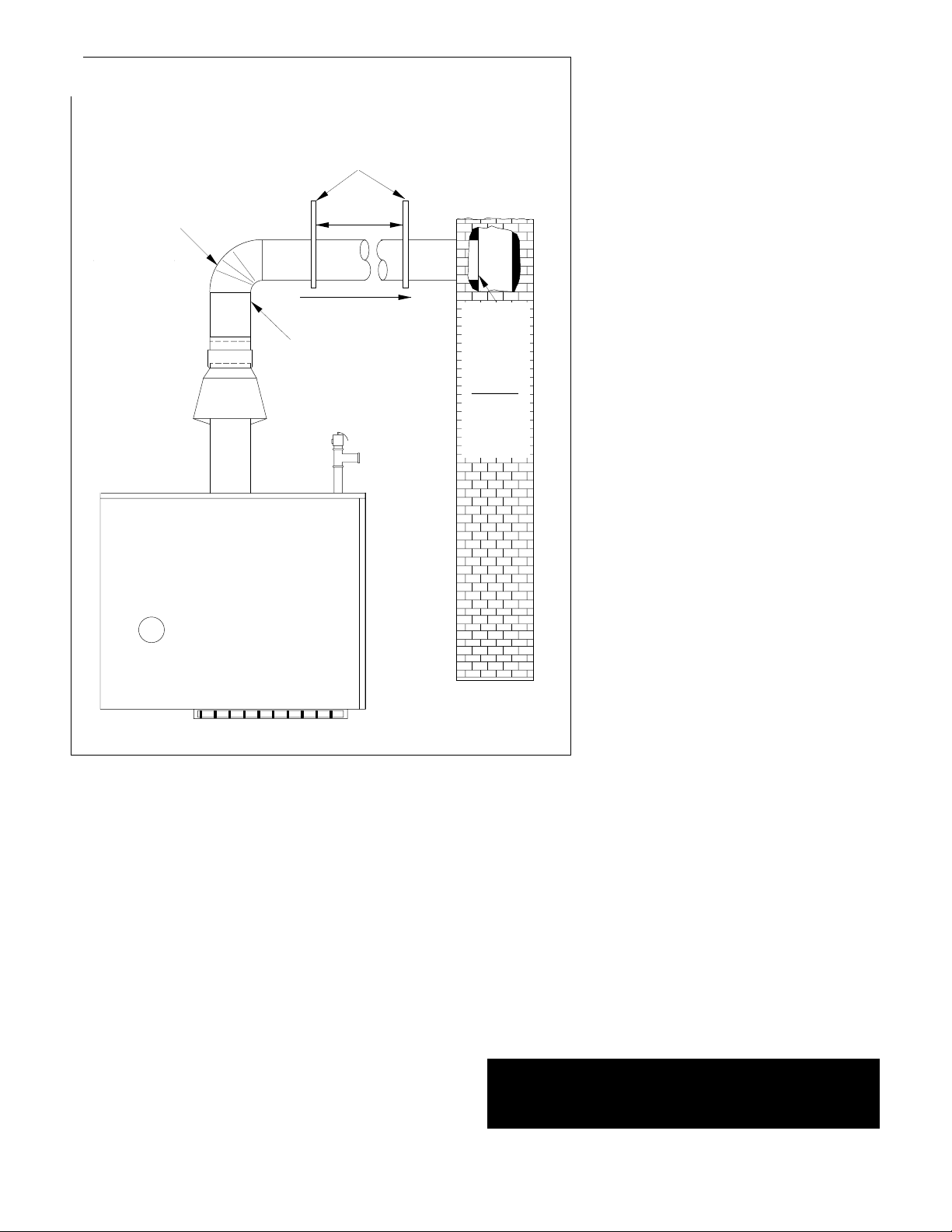
PROCEDURE C: Install flue pipe between vent damper and
chimney. A 6" minimum clearance is required
between flue pipe and all combustible construction.
FIGURE 1.15
DANGER: A chimney which does not meet modern
safety standards will result in a fire or deadly carbon monoxide poisoning of the building residents.
➤
USE VENT SUPPORT(S) AS REQUIRED TO PREVENT SAGGING
MAXIMUM
SINGLE WALL
6-FT
APART
OR TYPE B
FLUE PIPE
EW-65 = 5"
EW-85 = 5"
EW-100 = 5"
EW-125 = 6"
EW-145 = 6"
EW-165 = 7"
PITCH 1/4"
PER FOOT
SECURE
FLUE PIPE
TO VENT
DAMPER
INSTALL
FLUSH
WITH
INSIDE
CHIMNEY
LINER
SEAL
WITH
FURNACE
CEMENT
Page 10

FIGURE 1.16
PROCEDURE A: Select gas pipe size which will result in a pressure drop of less than 0.3" W.C.
for natural gas or 0.5" W.C. for propane, following example below.
Example: Boiler Model EW-125 is to be installed. Distance from existing gas meter to installation site is 20 ft.
What pipe size must be used? Local utility indicates heating value of natural gas being supplied is 1020 Btu per
cu.ft. Determine cubic feet of gas per hour for above boiler model:
125,000 Btu per hour
= 122.5 cu.ft. per hour
1020 Btu per cu.ft.
1. Find 20 ft. in upper portion of the table for natural gas under “Length of Pipe, Feet ” heading.
2. Moving down the column, match required capacity. Higher capacity acceptable. In our case it is 190 cu.ft.
3. Move to left-hand column “Nominal Iron Pipe Size, Inches”; read required pipe size. In our case it is 3/4
4. Take into account the effects of pipe fittings when determining the correct pipe size.
10
STEP 4: INSTALLING & TESTING GAS PIPING
➤
10 20 30 40 50 60 70 80 90 100 125 150 175 200
10 20 30 40 50 60 70 80 90 100 125 150
Maximum Capacity of Pipe in Thousands of Btu per Hour of Undiluted Liquefied
Petroleum gases (at 11 Inches of Water Column Inlet Pressure)
(Based of a Pressure Drop of 0.5 Inch Water Column)
.326 32 22 18 15 14 12 11 11 10 9 8 8 7 6
.493 72 49 40 34 30 27 25 23 22 21 18 17 15 14
.622 132 92 73 63 56 50 46 43 40 38 34 31 28 26
.824 278 190 152 130 115 105 96 90 84 79 72 64 59 55
1.049 520 350 285 245 215 195 180 170 160 150 130 120 110 100
1.380 1,050 730 590 500 440 400 370 350 320 305 275 250 225 210
1.610 1,600 1,100 890 760 670 600 560 530 490 460 410 380 350 320
2.067 3,050 2,100 1,650 1,450 1,270 1,150 1,500 990 930 870 780 710 650 610
2.469 4,800 3,300 2,700 2,300 2,000 1,850 1,700 1,600 1,500 1,400 1,250 1,130 1,050 980
3.026 8,500 5,900 4,700 4,100 3,600 3,250 3,000 2,800 2,600 2,500 2,200 2,000 1,850 1,700
4.026 17,50012,000 9,700 8,300 7,400 6,800 6,200 5,800 5,400 5,100 4,500 4,100 3,800 3,500
1/4"
3/8"
1/2"
3/4"
1"
1-1/4"
1-1/2"
2"
2-1/2"
3"
4"
Nominal
Iron Pipe
Size,
Inches
Internal
Diameter,
Inches
Length of Pipe, Feet
Maximum Capacity of Pipe in Cubic Feet of Natural Gas per Hour for Gas Pressures of
0.5 Psig or Less and a Pressure Drop of 0.3 Inch Water Column
(Based on a 0.60 Specific Gravity Gas)
Nominal
Iron Pipe
Size,
Inches
Length of Pipe, Feet
275 189 152 129 114 103 96 89 83 78 69 63
567 393 315 267 237 217 196 185 173 162 146 132
1071 732 590 504 448 409 378 346 322 307 275 252
2205 1496 1212 1039 937 834 771 724 677 630 567 511
3307 2299 1858 1559 1417 1275 1180 1086 1023 967 866 787
6221 4331 3465 2992 2646 2394 2205 2047 1921 1811 1606 1498
1/2"
3/4"
1"
1-1/4"
1-1/2"
2"
Page 11
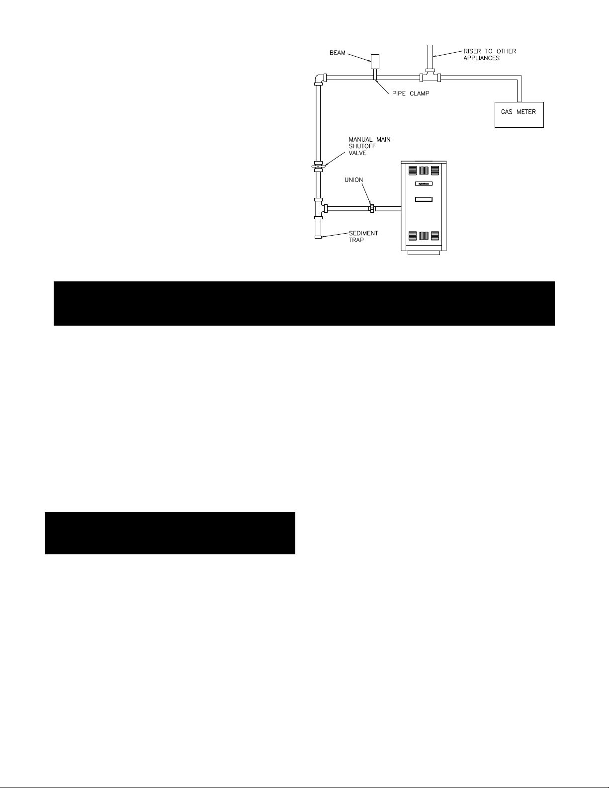
DANGER: Before placing gas piping into service, carefully test it to ensure every joint is gas tight. Leak
test all joints with a soap solution. NEVER TEST WITH AN OPEN FLAME AS FIRE OR EXPLOSION MAY
RESULT!
For any pressure testing in excess of 1/2 psi, the
boiler and its individual shutoff valve must be isolated
from the piping system by disconnecting them and
capping the outlet(s). For any pressure testing equal
to or less than 1/2 psi, the boiler must be isolated from
the piping system by closing its manual shutoff valve.
Minimum pressure required at the gas valve inlet is
5" W.C. for natural gas and 11" W.C. for propane.
Maximum pressure allowable at the gas valve inlet is
12"W.C. If the gas pressure is above this limit, a
pressure regulator must be installed. If the gas
pressure is below these limits, contact the local utility.
PROCEDURE C: Test Gas Piping:
When testing has been completed, close main gas shut-off valve
& set boiler combination gas valve in “off” position.
PROCEDURE B: Connect gas piping from
meter to boiler following good piping practices.
Pipe joint compound must be compatible with
LP gas. Check local codes and utilities for any
additional requirements.
ALL PIPING MUST BE SUPPORTED BY HANGERS, NOT BY BOILER OR ACCESSORIES.
FIGURE 1.17
11
STEP 5: WIRING THE BOILER
All electrical wiring must be in accordance with requirements of authority having jurisdiction or, in absence of
such requirements, to National Electric Code NFPA-70latest edition. If external source is utilized, boiler must
be electrically grounded in accordance with the requirements of authority having jurisdiction or, in absence of
such requirements, with National Electric Code NFPA70-latest edition. UL listed power limited circuit cable is
almost universally approved for safety controls on heating equipment, either internally or externally, without
protection of conduits or raceways.
For Canada, all electrical connections are to be made in
accordance with Standard C.S.A. C22.1 Canadian Electrical Code, Part 1 and Part 2 and/or local codes.
NOTE: If any original wire supplied with the boiler
must be replaced, use similar wire of 105 C rating.
Otherwise, insulation may melt or degrade, exposing bare wire.
NOTE: The boiler transformer must not be used to
power external accessories such as zone valves or
relays. Otherwise, boiler transformer will be overloaded and will burn out.
A separate 115V, 60Hz power supply is recommended
for the boiler. Use standard 15-amp fuse and 14-gauge
wire from power supply to boiler. Follow the wiring
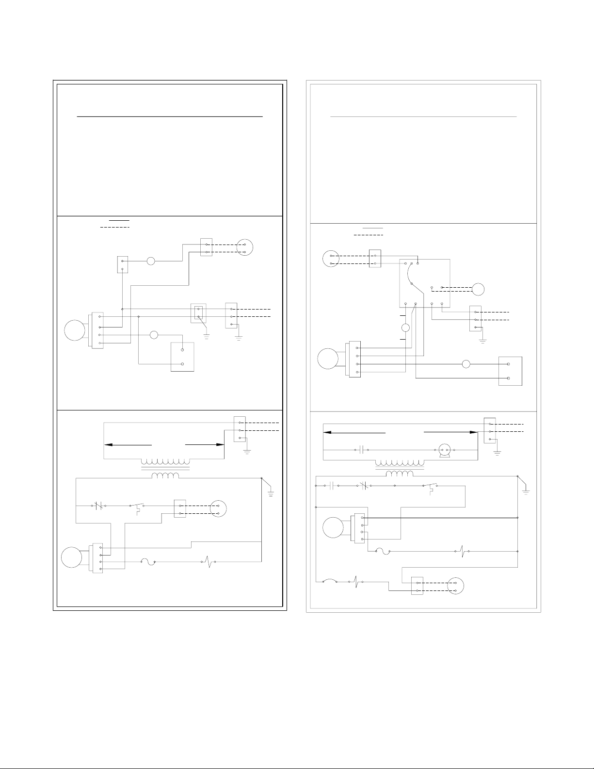
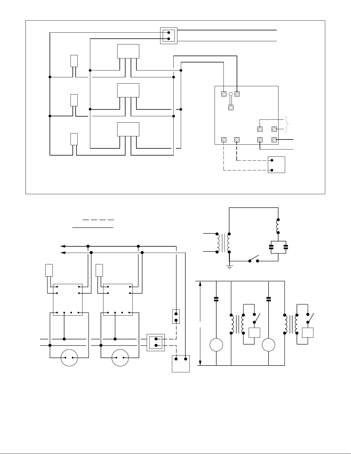
diagram for your par ticular installation as shown in
Figures 1.18 through 1.28.
WARNING: Turn off electric power supply before
servicing. Contact with live electric components
can cause shock or death.
➤
➤
Page 12
12
FIGURE 1.18: WIRING DIAGRAM & OPERATION
SEQUENCE FOR BOILERS WITH STANDING PILOT
& VENT DAMPER
FOR BOILERS EQUIPPED WITH STANDING PILOT
FIGURE 1.19: WIRING DIAGRAM & OPERATION
SEQUENCE FOR BOILERS WITH STANDING PILOT,
VENT DAMPER & L8148E AQUASTAT RELAY
OPERATING SEQUENCE
VENT DAMPER AND HI-LIMIT
MOTOR DRIVES VENT DAMPER TO CLOSED POSITION AND
REMAINS CLOSED DURING STANDBY.
STANDING PILOT REMAINS LIT.
SENSING CIRCUIT IS CONTINUOUSLY MONITORED.
THERMOSTAT (OR OPERATING CONTROL) CALLS FOR HEAT.
DAMPER BLADE OPENS.
DAMPER END SWITCH CLOSES (PROVING VENT DAMPER OPEN).
IF NO FAILURE EXISTS, THE MAIN VALVE IS ENERGIZED.
UNIT OPERATES UNTIL THERMOSTAT (OR OPERATING CONTROL)
IS SATISFIED.
SYSTEM RETURNS TO STANDBY WITH DAMPER CLOSED.
FACTORY WIRED
FIELD WIRED
VENT
DAMPER
HI-LIMIT
BLK
1
WHT
2
RED
3
BLUE
4
BLUE
SPILL
SWITCH
ROLLOUT
SWITCH
BLUE
WHT
BLK
24V GAS VALVE
115/24V
TRANSF.
TH
TR
FOR BOILERS EQUIPPED WITH VENT DAMPER
OPERATING SEQUENCE
STANDING PILOT AND L48148E
MOTOR DRIVES VENT DAMPER TO CLOSED POSITION AND
REMAINS CLOSED DURING STANDBY.
STANDING PILOT REMAINS LIT.
SENSING CIRCUIT IS CONTINUOUSLY MONITORED.
THERMOSTAT (OR OPERATING CONTROL) CALLS FOR HEAT.
DAMPER BLADE OPENS.
DAMPER END SWITCH CLOSES (PROVING VENT DAMPER OPEN).
MAIN VALVE IS ENERGIZED.
UNIT OPERATES UNTIL THERMOSTAT (OR OPERATING CONTROL)
IS SATISFIED.
SYSTEM RETURNS TO STANDBY WITH DAMPER CLOSED.
THERMOSTAT
OR OPER.
GND
T2
L1
L2
CONTROL
115V 60HZ
T1
TT
TT
FACTORY WIRED
FIELD WIRED
THERMOSTAT
OR OPER.
CONTROL
VENT
DAMPER
T1
TT
TT
BLUE
SPILL
SWITCH
BLUE
BLK
1
WHT
2
RED
3
BLUE
4
TW
Z
B2B1
L8148E
TV
C1 C2
L1 L2
ROLLOUT
SWITCH
CIRC.
T2
L1
L2
GND
115V 60 HZ
GAS VALVE
TH
TR
IF ANY OF THE ORIGINAL WIRE AS SUPPLIED WITH THE BOILER
MUST BE REPLACED, USE A SIMILIAR WIRE OF 105˚ C RATING.
GND
T2
L1
L2
115V 60HZ
115V AC
H
N
115/24V
THERMOSTAT
HI-LIMIT
VENT
DAMPER
SPILL AND ROLLOUT SWITCHES USED WHEN INPUT
IS LESS THAN 300,000 BTUH
1
2
3
4
SPILL
SWITCH
ROLLOUT
SWITCH
T1
TT
TT
OR OPER.
CONTROL
TRTH
GAS VALVE
42-5768
IF ANY OF THE ORIGINAL WIRE AS SUPPLIED WITH THE BOILER
MUST BE REPLACED, USE A SIMILIAR WIRE OF 105˚ C RATING.
L1
1K1
115 V AC
CIRC. MOTOR
C1
C2
T2
L1
115V 60 HZ
L2
GND
L2
115/24V
B
R
B1
1K2
HI-LIMIT
VENT
DAMPER
Z
SPILL AND ROLLOUT SWITCHES USED WHEN INPUT
IS LESS THAN 300,000 BTUH
1
2
3
4
ROLLOUT
SWITCH
W
1K
TV
T
SPILL SWITCH
T1
TT
TT
TH TR
GAS VALVE
THERMOSTAT
OR OPER.
CONTROL
B2
1
42-5769
Page 13
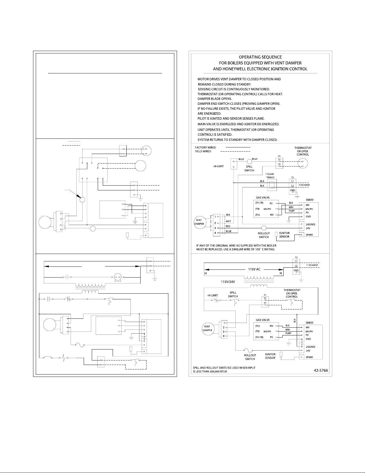
FOR BOILERS EQUIPPED WITH VENT DAMPER
FIGURE 1.22: WIRING DIAGRAM & OPERATION
SEQUENCE FOR BOILERS WITH IID,
VENT DAMPER & L8148E AQUASTAT RELAY
13
FIGURE 1.23: WIRING DIAGRAM & OPERATION
SEQUENCE FOR BOILERS WITH IID,
VENT DAMPER
OPERATING SEQUENCE
ELECTRONIC PILOT CONTROL AND L48148E
MOTOR DRIVES VENT DAMPER TO CLOSED POSITION AND
REMAINS CLOSED DURING STANDBY.
SENSING CIRCUIT IS CONTINUOUSLY MONITORED.
THERMOSTAT CALLS FOR HEAT.
DAMPER BLADE OPENS.
DAMPER END SWITCH CLOSES (PROVING DAMPER OPEN).
IF NO FAILURE EXISTS, THE PILOT VALVE AND IGNITOR
ARE ENERGIZED.
PILOT IS IGNITED AND SENSOR SENSES FLAME.
MAIN VALVE IS ENERGIZED AND IGNITOR DE-ENERGIZED.
UNIT OPERATES UNTIL THERMOSTAT IS SATISFIED.
SYSTEM RETURNS TO STANDBY WITH DAMPER CLOSED.
FACTORY WIRED
FIELD WIRED
AQUA. RELAY
L8148E
SPILL
SWITCH
1
2
VENT
DAMPER
IF ANY OF THE ORIGINAL WIRE AS SUPPLIED WITH THE BOILER
MUST BE REPLACED, USE A SIMILIAR WIRE OF 105˚ C RATING.
SPILL AND ROLLOUT SWITCHES USED WHEN INPUT
IS LESS THAN 300,000 BTUH
DAMPER
Z
L1
1K2
VENT
3
4
1K1
B
HI-LIMIT
1
2
3
4
W
1K
WHT
BLUE
BLK
RED
R
ROLLOUT
SWITCH
Z
T
B2
B1
BLUE
115 V AC
TV
ROLLOUT
SWITCH
B1
TV
T
C2
C1
L2L1
GAS VALVE
(TH-TR)
(TR)
(TH)
CIRC. MOTOR
C1
MANUAL RESET
SPILL SWITCH
(TH)
(TR)
MV/PV
(TH-TR)
GAS VALVE
T1
L1
L2
PV
MV/PV
MV
IGNITOR
SENSOR
115/24V
MV
PV
IGNITOR
SENSOR
T1
TT
TT
C2
CIRCULATOR
T2
L1
L2
GND
BLK
BRN
PURP
L2
BLK
BRN
PURP
THERMOSTAT
OR OPER.
CONTROL
115V 60HZ
S8600
MV
MV/PV
PV
GND
24(GND)
24V
SPARK
T2
L1
115V 60HZ
L2
GND
S8600
MV
MV/PV
PV
GND
24(GND)
24V
SPARK
THERMOSTAT
OR OPER.
CONTROL
B2
42-5767
Page 14
TH1
14
FIGURE 1.20: WIRING DIAGRAM FOR ZONING WITH ZONE VALVES
FIGURE 1.21: WIRING DIAGRAM FOR ZONING WITH CIRCULATORS
YEL
ZV1
N
115V
H
T2
RED
TH2
TH3
T2: 24V TRANSF.
TH1: ZONE T'STAT
TH2: ZONE T'STAT
TH3: ZONE T'STAT
F ACT ORY WIRING
FIELD WIRING
TO
ADDITIONAL
ZONES
YEL
ZV2
YEL
YEL
ZV3
YEL
YEL
ZV1: ZONE VALVE
ZV2: ZONE VALVE
RED
RED
R1
RED
RED
RED
R1: AQUASTAT RELAY - L8148E
GV: GAS VALVE
W
TV T
2
B1 B2
C1 C2
L1
ZV3: ZONE VALVE
T1
115V
1R-2
L2
TH
TR
GAS VALVE
COIL
TO CIRC.
N
115V
H
GV
2R-2
TH1
X
T
X
T
ZR1
31
2
4
H
115V
N
C1
C1: ZONE CIRCULATOR
C2: ZONE CIRCULATOR
TH1: ZONE T'STAT
TH2: ZONE T'STAT
T2
H1
TH1
TH2
T
T
ZR2
14
2
BLACK
BOILER CIRCUIT
X
X
1R-1
3
H1
115V
ZR1 ZR2
CIRC.
1
T1
TH
C2
GV
TR
WHITE
EXTERNAL CIRCUIT
ZR1: ZONE RELAY (RA832A
OR EQUIVALENT)
ZR2: ZONE RELAY (RA832A
OR EQUIVALENT)
H1: HI-LIMIT AQUASTAT
GV: GAS VALVE
T1: 24V TRANSFORMER
T2,T3: TRANSF. (IN RELAYS)
1R-1, 1R-2: ZR1 CONTACTS
2R-1, 2R-2: ZR2 CONTACTS
CIRC.
2
2R-1
T3
TH2
Page 15
SAFETY CONTROLS
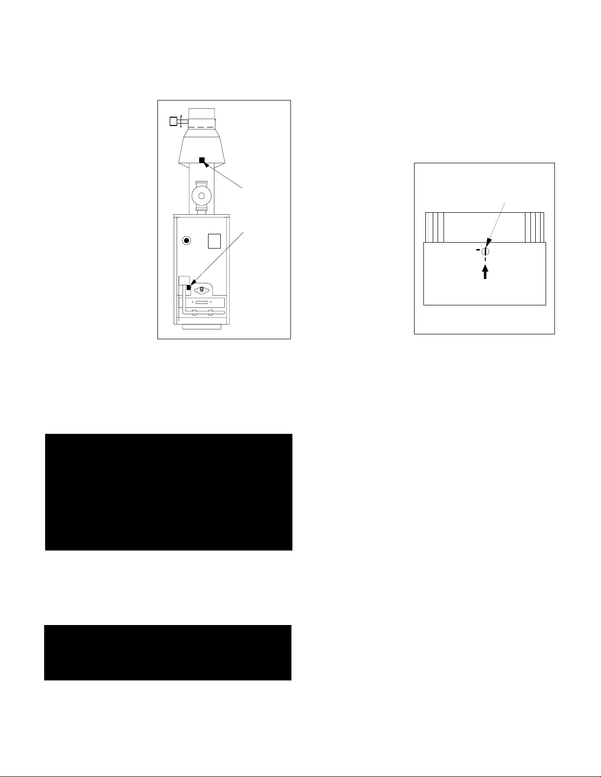
The spill switch, see Figure 2.1, detects the escape of
combustion products through the draft hood relief opening and interrupts the
power to the gas valve
preventing unsafe boiler operation. Escape
of flue products could
be caused by a
blocked or collapsed
chimney or by inadequate chimney draft.
This is a manual reset-type device and
can be reactivated by
depressing the spill
switch reset button.
The flame rollout
switch, see Figure 2.1,
prevents flame rollout
from the boiler combustion chamber,
caused by blocked
boiler flue passageways, by interrupting power to the gas valve to prevent
unsafe boiler operation.
This is either a single use
device and must be replaced if it is tripped or a manual reset-type device that can be reset by depressing
the reset button. Flue passages must be inspected by a
qualified installer, prior to switch replacement, if a problem occurs .
START-UP & ADJUSTMENTS
Safe lighting and other performance criteria were met
with the gas manifold and control assembly provided on
the boiler when the boiler underwent tests specified in
ANSI Z21.13-latest edition.
1. Bleed all heating system air vents, starting on lowest
floor. Open vents one at a time until water squirts out.
Close vent and repeat procedure with remaining vents.
2. Make sure boiler combination gas valve is in OFF
position. Then, open main gas shutoff valve, allowing
gas to flow to boiler.
3. Set thermostat heat anticipator at .8 amp when
therm-ostat is controlling boiler directly. When zone controlled, set heat anticipator to amp draw of zone valve(s)
or circulator pump relay.
4. Set thermostat to
call for heat and turn
on electrical power to
boiler. Observe that
vent damper position
indicator has rotated
to open position, see
Figure 2.2.
Damper
must be in open
position when boiler main burner is
operating.
In case of a damper
malfunction, the
damper blade may
be manually placed
in the full open position to permit burner operation. To
accomplish this follow the instructions on the damper.
5. Allow circulator to run 15 to 30 minutes, which should
purge any leftover air from system. Check automatic air
vent for the proper operation and the entire system for
any leaks. Make sure all air is purged from system
before lighting boiler.
6. Set thermostat to no longer call for heat. Observe that
damper position indicator rotates to the closed position.
7. Set thermostat to lowest setting and light boiler following lighting instructions in Figure 2.4. Boiler is equipped
with flame rollout switch to shut down boiler in case of
sustained flame roll-out or excessive heat be-hind front
panel. If switch opens, see the information on “Safety
Controls” on this page.
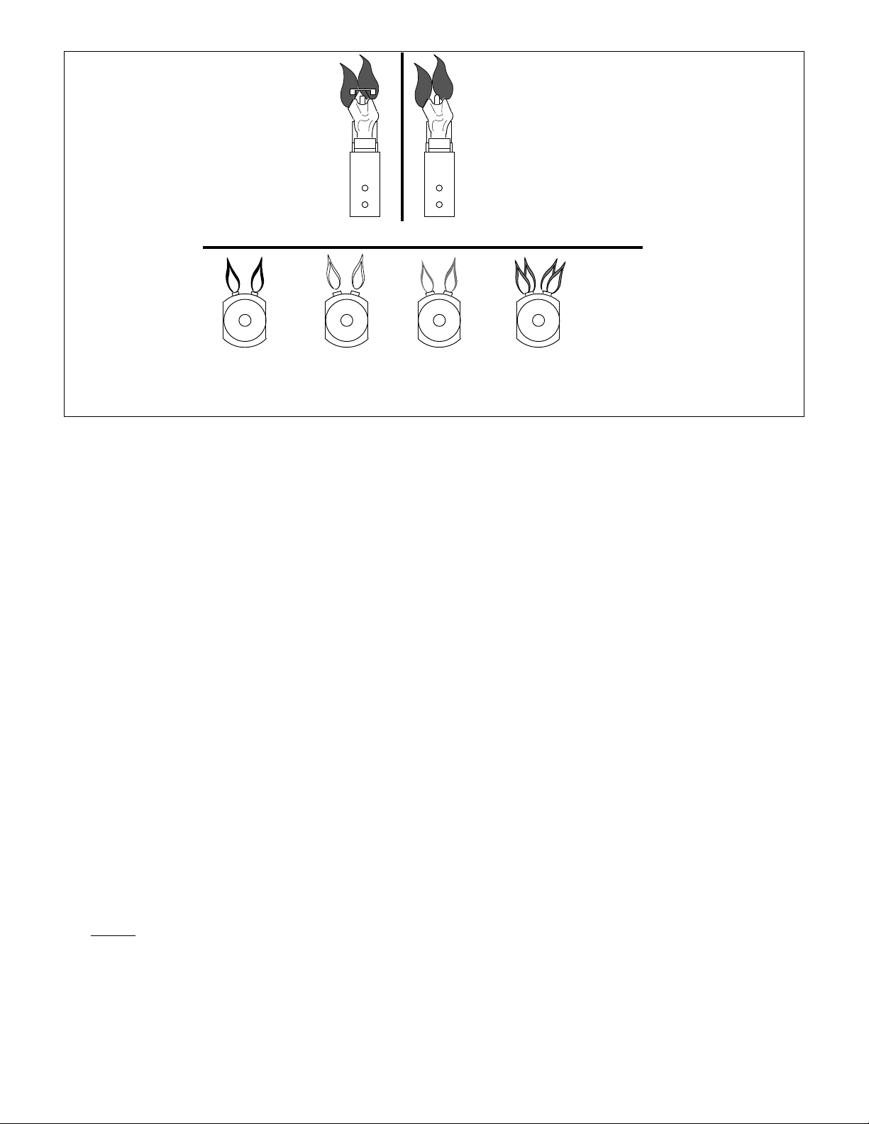
8. Observe pilot and main burner flame, see Figure 2.3.
All burner ports should be ignited and burn with a
steady blue flame.
START-UP & OPERATION
15
FIGURE 2.1
DANGER: If flame rollout switch or spill switch trips
repeatedly during start-up or operation, it indicates
a hazardous condition that must be corrected
immediately.
WARNING: If boiler cannot be restored to normal
operation after resetting of spill switch, or if flame
rollout switch has tripped, do not attempt to put the
boiler in operation. Immediately contact a qualified
service professional.
WARNING: Keep boiler area clear and free from
combustible materials, gasoline and other
flammable vapors and liquids. Otherwise, fire or
explosion may result.
FIGURE 2.2
CAUTION: Never leave the job with yellow burning
flames. This condition indicates poor combustion
and will quickly carbonize the boiler, reducing efficiency and boiler life. It may also be an indication of
improper venting or combustion air supply. If
unable to adjust flame properly, consult your local
utility.
SPILL
SWITCH
ROLLOUT
SWITCH
DAMPER POSITION INDICATOR
MUST BE IN VISIBLE LOCATION
FOLLOWING INSTALLATION.
CLOSED
OPEN
FLOW DIRECTION
Page 16
9. Boilers are shipped from the factory with the primary
air shutters on the main burner wide open. It is recommended these air shutters be left in the wide open position unless there is lifting of the flame above the burner
ports. If there is lifting, the air shutters should be gradually closed until the lifting is eliminated. It may also be
necessary to adjust the primar y air shutters if the input
rate is reduced by a change in the orifices.
10. After burner has been in operation for about 10 minutes, check gas input rate to boiler as follows:
a. Make sure that all appliances served by the gas
meter are turned off during timing of gas input rate to
the boiler.
b. Measure the time in seconds that it takes for the boiler to use10 cubic feet of gas. Divide 36,000 by the
number of seconds, this is the number of cubic feet of
gas used per hour. Multiply this figure by the heating
value of the gas to obtain the input in Btu per hour.
Example: An HC-125E boiler takes 4 minutes, 54 seconds to use 10 cubic feet of natural gas. Local utility
indicated heating value of the natural gas being supplied
is 1020 Btu/cu ft. Therefore:
54 + (4x60) = 294 seconds
36,000
x 1020 = 124,898 Btu/hr
294
Therefore, the boiler input is correct.
NOTE: Before calculating the input of the heating
equipment, obtain the heating value of the gas from
the local utility.
11. If boiler input needs to be corrected, adjust the combination gas valve pressure regulator. Regulator is factory set
at 3.5" W.C. for natural gas or 10" W.C. for propane. Turn
adjusting screw clockwise to increase gas flow, increase
input. Turn adjusting screw counterclockwise to decrease
gas flow (decrease input). In no case, should final manifold
pressure setting vary more than .2" from factory-set
pressures. If rated input cannot be obtained with regulator
adjustment, gas supply pressure or orifice size may be the
cause. Consult your local utility and Hydrotherm.
12. The gas burner orifices supplied with the boiler have
been carefully designed to provide the correct gas input
rate for most gas conditions typically found in the U.S.
Occasionally, however, the local gas characteristics may
not allow the unit to be properly adjusted for input. If this is
the case, the local utility or Hydrotherm may recommend
the orifices be changed. When changing orifices, follow
the procedures in the Maintenance Section of this manual.
13. Start and stop burners several times by raising and
lowering the thermostat setting.
14. After the boiler has been firing long enough to raise
the boiler water temperature to above the minimum
setting of the high limit, check the high limit by turning its
setting from maximum to minimum setting. This should
turn the boiler off. Return high limit to desired setting.
15. Check boiler safety shut-off controls.
a. For boilers with standing pilot, with boiler firing,
disconnect thermocouple lead from the valve. The
valve should close.
b. For boilers with intermittent pilot, with boiler firing, dis-
connect wire connection to the "PV" terminal on Honeywell S8600 control. The gas valv e should close .
16
Q345A
FIGURE 2.3
INTERMITTENT
IGNITION PILOT
MODELS
Q314A/Q309A
CONSTANT PILOT
MODELS
NORMAL PILOT FLAME
NORMAL
(HARD FLAME)
LIFTING
(TOO MUCH AIR)
(MARGINAL)
MAIN BURNER FLAMES
YELLOW
TIPPING
YELLOW
FLAME
(TOO LITTLE AIR)
Page 17
17
WARNING
If you do not follow these instructions exactly, a fire or explosion may result
with property damage, personal injury, or loss of life.
A. Before lighting, smell all around the appliance area for gas.
Be sure to smell next to the floor because some gas is heavier
than air and will settle on the floor.
WHAT TO DO IF YOU SMELL GAS
• Do not try to light any appliance.
• Do not touch any electrical switch; do not use any phone
in your building.
• Immediately call your gas supplier from a neighbor's
phone. Follow the gas supplier's instructions.
• If you cannot reach your gas supplier, call the fire
department.
B. Use only your hand to turn the gas control knob. Never use
tools. If the knob will not turn by hand, don't try to repair it, call
a qualified service technician. Force or attempted repair may
result in a fire or explosion.
C. Do not use this appliance if any part has been under water.
Immediately call a qualified service technician to inspect the
appliance and to replace any part of the control system and
any gas control which has been underwater.
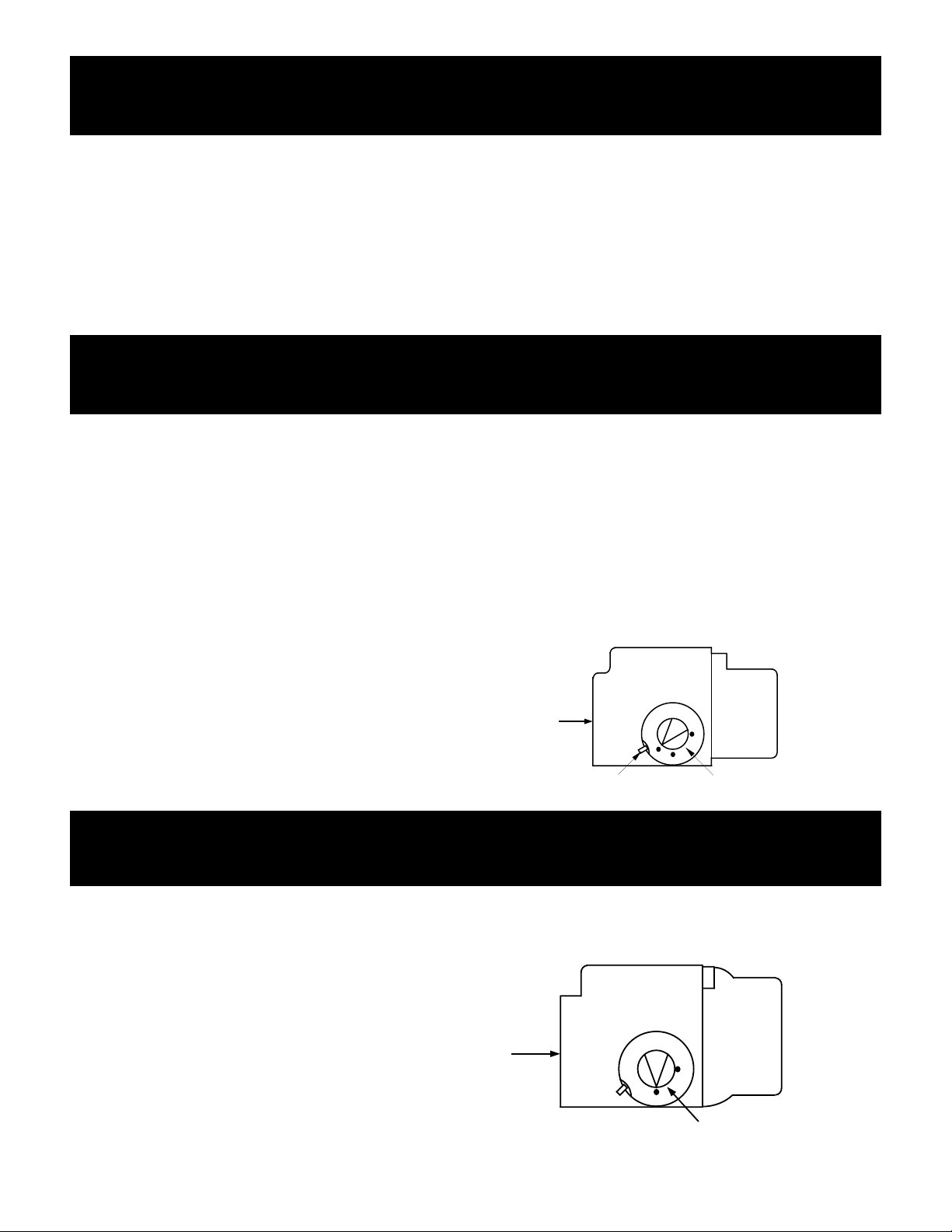
LIGHTING CONTINUOUS PILOT INSTRUCTIONS
Honeywell VR8200
Natural or Propane Gas
This appliance has a pilot which must be lit by hand. When lighting the pilot, f ollow these instructions exactly.
1. STOP! Read the safety information above on this page.
2. Set the thermostat to lowest setting.
3. Turn off all electric power to the appliance.
4. Turn gas control knob clockwise to "OFF" position. Do not
force.
5. Wait five (5) minutes to clear out any gas, then smell for
gas, including near the floor. If you smell gas,
STOP! Follow "A" in the safety information above. If you don't smell
gas, go to the next step.
6. Remove the base door covering the top of the burners and
enclosing the pilot.
7. Find pilot. Follow metal tube from gas control. The pilot is
between the central burner tubes behind the base door.
8. Turn knob on gas control counterclockwise to "Pilot" position.
9. Push down and hold the red button next to the control
knob. Immediately light the pilot with a match. Continue to
hold the red button down for about one (1) minu te after the
pilot is lit. Then turn knob to "ON" position. If it goes out,
repeat steps 4 through 9.
• If button does not pop up when released, stop immediately and call your service technician or gas supplier.
• If the pilot will not stay lit after several tries, turn the gas
control "OFF" and call your service technician or gas
supplier.
10. Replace the base door.
11. Turn gas control knob counterclockwise to "ON".
12. Turn on all electric power to the appliance.
13. Set thermostat to desired setting.
OPERATING INSTRUCTIONS
Intermittent Pilot - Honeywell VR8204
Natural or Propane Gas
1. STOP! Read the safety information above.
2. Set the thermostat to lowest setting.
3. Turn off all electric power to the appliance.
4. This appliance is equipped with an ignition device which
automatically lights the pilot. Do not try to light the pilot by
hand.
5. Turn gas control knob clockwise to "OFF". Do not force.
6. Wait five (5) minutes to clear out any gas. Then smell for
gas, including near the floor. If you then smell gas,
STOP!
Follow "A" in the safety information above. If you don't
smell gas, go to next step.
7. Turn gas control knob counterclockwise to "ON".
8. Turn on all electric power to the appliance.
INLET
GAS CONTROL KNOB
SHOWN IN "OFF" POSITION
GAS
ON
OFF
9. Set thermostat to desired setting.
10. If the appliance will not operate, follow the instructions "To
Turn Off Gas To Boiler" on next page and call your service
technician or gas supplier.
GAS
INLET
RESET BUTTON
ON
OFF
PILOT
GAS CONTROL KNOB
SHOWN IN "OFF" POSITION
Page 18

This boiler has been designed to provide years of trouble free performance in normal installations. Examination by the homeowner at the beginning of each heating
season, and in mid-heating season, should assure continued good performance. In addition, the boiler should
be examined by a qualified service professional at least
once every year.
NOTE: Boiler is not for use in systems where water
is replenished. Do not draw water from system for
cleaning. Minerals in water can build up on heat
transfer surfaces and cause overheating and subsequent failure of cast iron sections.
NOTE: If boiler is equipped with a low water cutoff,
follow manufacturer’s maintenance instructions.
WATER TREATMENT
Water treatment is recommended in areas where water
quality is a problem. A local water treatment company
should be consulted to determine the requirements for
your particular system.
FREEZE PROTECTION
Where absolutely necessary, system antifreeze can be
utilized. It must be compatible with hydronic heating systems. System must be designed to accommodate necessary changes in heat transfer, pump head, flow rate &
expansion. For more information, consult The Hydronics
Institute Technical Topics Number 2A publication.
Note: Never use an RV-type antifreeze protection
solution nor an automotive-type antifreeze as damage to the boiler and other system components may
result.
18
MAINTENANCE
DANGER: To avoid fire and explosion hazards: Do
not store anything against boiler or allow dirt/debris
to accumulate in area immediately surrounding
boiler. Keep boiler area clear and free from combustible materials, gasoline and other flammable
vapors and liquids. Do not allow lint, paper or rags
to accumulate near burners. Do not place clothing
on boiler to dry.
BEFORE EACH HEATING SEASON
1. Remove and inspect draft hood and vent piping connecting draft hood to chimney or vent for obstructions,
soot accumulation, rust or corrosion. Clean and replace
as necessary. Check tightness of joints; seal all joints
where necessary.
2. Check boiler flue passageways in the boiler sections
for any blockage or soot accumulation. Remove draft
hood, jacket top and cast iron dome. Using a flash light,
examine all flue passageways.
a. If passageways are free of soot and obstructions,
replace dome and seal with furnace cement or high temperature silicone adhesive/sealant.
b. If passageways need cleaning, remove burners as
described in paragraph 3 below. Insert long-handle br istle flue brush down between section tubes and upward
through sections from combustion chamber in both diagonal directions to remove carbon from finned surfaces.
Vacuum debris. Replace dome and seal with furnace
cement or high temperature silicone adhesive/sealant.
c. Reinstall jacket top panel and draft hood.
3. Check and clean burner assembly. Remove burner
access panel. To remove burners, lift up and to rear until
burners are disengaged from orifices. Brush top of burners with soft bristle brush; blow out with air or vacuum.
4. Check gas manifold for proper position and reassemble burners to the manifold. Line up holes in burners
with the orifices and slide assembly back into position.
BE SURE TO REINSTALL BURNER WITH PORTS ON
THE TOP SURFACE, UPRIGHT.
5. When a low water cut-off has been utilized, follow the
manufacturer’s maintenance instructions. As a minimum, test electronic control operation at least once a
year. Float type controls should be flushed twice a year.
6. Lubricate circulator motor according to manufacturer’s
instructions. This information may be contained in labeling on the pump frame.
7. Follow “System Start-Up & Adjustments” procedures
in the “Start-up & Operation” section of this manual.
TO TURN OFF GAS TO BOILER
3. Turn gas control knob clockwise to "OFF" position.
1. Set thermostat to lowest setting.
2. Turn off all eletrical power to the appliance if service is
to be performed.
WARNING: Do not obstruct the flow of combustion
and ventilation air. Failure to comply with this warning can result in carbon monoxide poisoning!
Page 19
19
HOW TO CHANGE ORIFICES
1. Shut off power supply and gas supply to the boiler.
2. Remove burner access panel. To remove burners, lift
up & to rear until burners are disengaged from orifices.
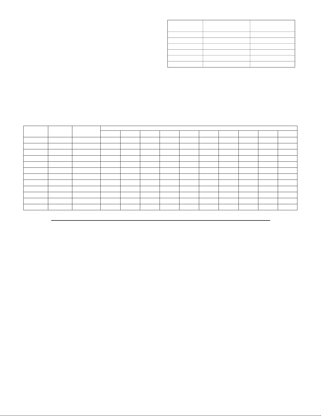
3. Check orifices for proper drill size. Size is stamped
onto the body of the brass orifice. The size can also be
checked by using a pin gauge, see Figure 3.1. All orifices are screwed into the manifold and may be removed
by using a 5/8” wrench or socket.
4. Reverse above procedures to install orifices & burners. BE SURE TO INSTALL BURNERS WITH BURNER
PORTS ON TOP SURFACE, UPRIGHT.
FIGURE 3.1
NO HEAT
1. Blown fuse or circuit breaker.
2. Power switch turned off.
3. Vent damper not open.
4. Circulator not running.
5. Air in lines and radiation.
6. Tripped rollout switch.
7. Tripped spill switch.
INSUFFICIENT HEAT
1. Incorrect t’stat anticipator setting.
2. Hi-limit control setting too low.
3. Boiler undersized or underfired.
4. Insufficient radiation.
5. Air traps in lines or radiation.
OVERHEATING
1. Wrong thermostat anticipator setting.
2. Bad thermostat location.
3. Bad thermostat.
ODOR, EXCESSIVE MOISTURE IN
BUILDING
1. Leak in piping.
2. Carbon build-up in flueways.
3. Blocked chimney.
4. Downdrafts- incorrect termination.
YELLOW FLAME, CARBON
BUILD-UP
1. Unit overfired.
2. Air shutter misadjustment.
3. Wrong orifices.
4. Burning in burner mixing tube.
5. Inadequate combustion air.
6. Inadequate draft (flue blockage).
NOISE
1. Ignition-incorrect air shutter adjustment.
2. Whistle due to burr on orifices.
3. Burner “fluteing” -air shutter open-
ing too wide.
TROUBLESHOOTING
CAUTION: Label all wires prior to disconnection when servicing controls. Wiring errors can cause improper
and dangerous operation. Verify proper operation after servicing.
Orifice Size
Model # Fuel Type Orifice Qty. Sea Level 2000 ft. 3000 ft. 4000 ft. 5000 ft. 6000 ft. 7000 ft. 8000 ft. 9000 ft. 10000 ft.
EW-65 NG 2 2.60mm 39 40 41 41 42 42 43 43 44
EW-65LP 2 52525353535353545454
EW-85NG 2 32333435353636373840
EW-85LP 2 49505050515151525252
EW-100 NG 3 37 38 39 39 40 41 42 42 43 43
EW-100 LP 3 1.65mm 52 53 53 53 53 53 54 54 54
EW-125 NG 4 39 40 41 41 42 42 43 43 44 44
EW-125 LP 4 1.60mm 1.60mm 53 53 53 53 53 54 54 54
EW-145 NG 4 35 36 36 37 37 38 39 40 41 42
EW-145 LP 4 51 51 52 52 52 52 53 53 53 54
EW-165 NG 4 32 33 34 35 35 36 36 37 38 40
EW-165 LP 4 1.85mm 50 50 50 51 51 51 52 52 52
EQUIVALENT ORIFICE SIZES AT HIGH ALTITUDES
INCLUDES 4% INPUT REDUCTION FOR EACH 1,000 FEET
MODEL
EW-65
EW-85
EW-100
EW-125
EW-145
EW-165
NAT. GAS
DRILL SIZE
2.60MM
32
37
39
35
32
L.P. GAS
DRILL SIZE
52
49
1.65MM
1.60MM
51
1.85MM
Page 20
APPENDIX A
20
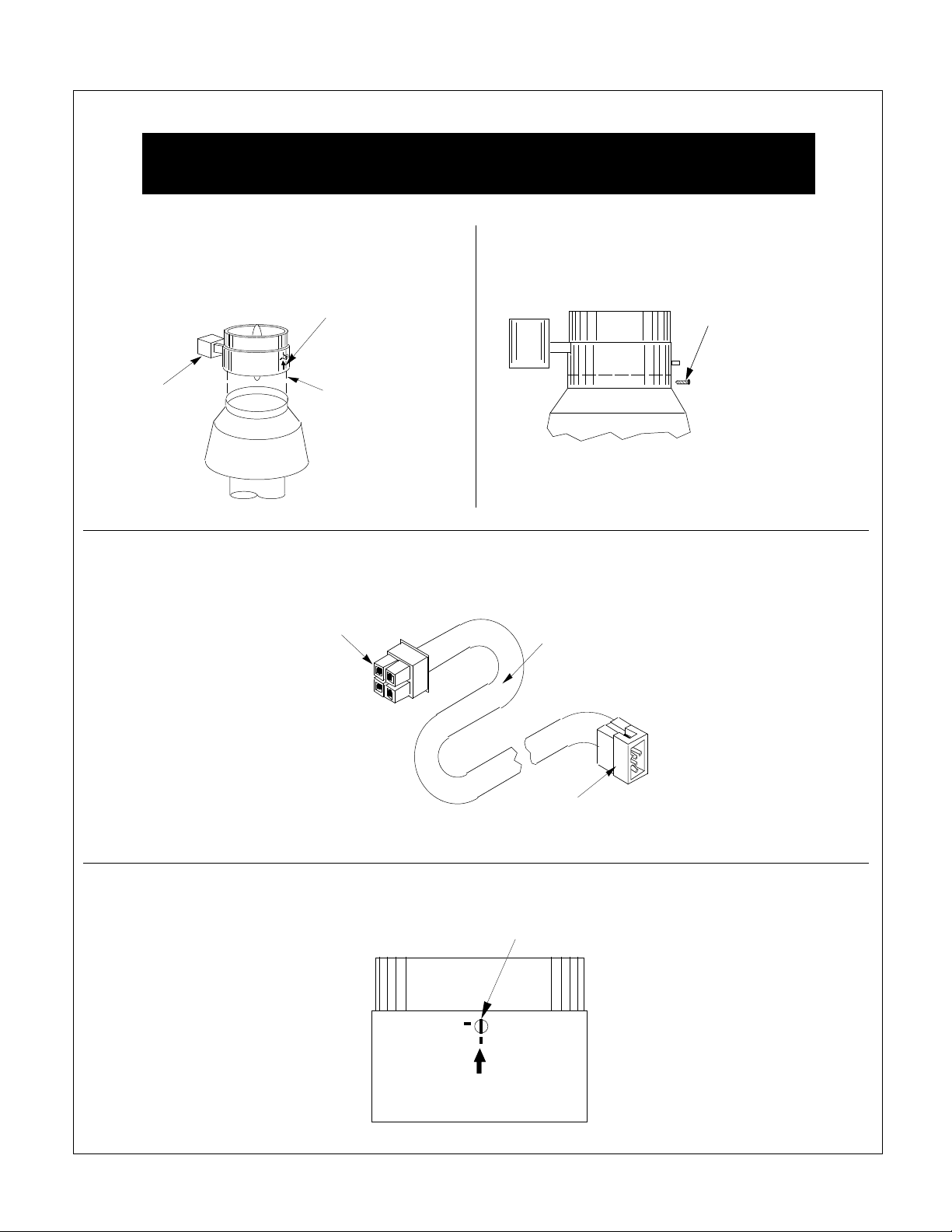
MÉTHOD D' INSTALLATION B: pour le volet motorisé de ventilation.
Danger: Le volet de ventilation doit servir seulement à la chaudière. Ne pas l'utilser
pour ventiler d'autres appareils; sinon cela pourrait provoquer un incindie ou causer un
empoisonnment par le monoxyde de carbone.
1. Monter le volet de ventilation sur la partie
supérieure du coupe-tirage.
2. Fixer le volet de ventilation au coupe-tirage.
3. Brancher le faisceau de fils.
`
LA FLECHE DE DIRECTION
'
'
DE LECOULEMENT POINTE
VERS LE HAUT
SASSURER QUE
'
LE MOTEUR SOIT
'
SITUE A GAUCHE
MONTER LE VOLET
DE VENTILATION
AU-DESSUS DU
COUPE-TIRAGE.
FIGURE 1.12
ENFICHER DANS LA PRISE
`
MOLEX A L INTERIEUR DU
MOTEUR DU VOLET DE
VENTILATION.
'
'
ATTACHER LA PARTIE
'
INFERIEURE DU VOLET
DE VENTILATION AU
COUPE-TIRAGE A LAIDE
DE VIS DE 1/2 po OU PLUS
COURTES OU DES RIVETS
AVEUGLES.
FIGURE 1.13
FAISCEAU DE FILS
DU VOLET DE
VENTILATION.
`
'
FIGURE 1.14
ENFICHER DANS LA PRISE
MOLEX SUR LE DEVANT
DE LA CHAUDIERE.
LE REGISTRE DOIT ETRE EN
POSITION OUVERTE LORSQUE
^
LE BRULEUR PRINCIPAL EST EN
^
MARCHE.
CLOS
OUVERTE
SENS DE DEBIT
`
FIGURE 2.2
Page 21
21
Page 22

22
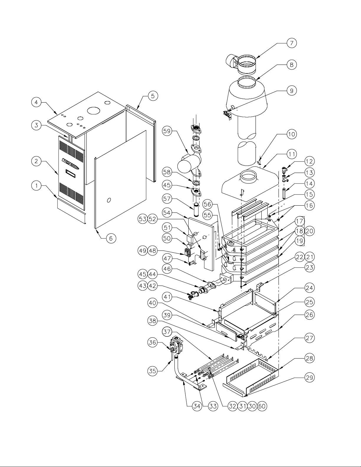
— Jacket Complete BM-9630 1
Jacket Complete BM-9631 1 1
Jacket Complete BM-9632 1
Jacket Complete BM-9633 1 1
1 Lower Front Inner Panel 03-1519 111111
2 Front Door Panel 03-1515 1
Front Door Panel 03-1516 1 1 1
Front Door Panel 03-1517 1 1
3 Jacket Side Panel - LH 03-1503 1
Jacket Side Panel - LH 03-1504 1 1 1
Jacket Side Panel - LH 03-1505 1 1
4 Jacket Top Panel 03-1512 1 1 1
Jacket Top Panel 03-1513 1
Jacket Top Panel 03-1514 1 1
5 Jacket Rear Panel 03-1509 1
Jacket Rear Panel 03-1510 1 1 1
Jacket Rear Panel 03-1511 1 1
6 Jacket Side Panel - RH 03-1500 1
Jacket Side Panel - RH 03-1501 1 1 1
Jacket Side Panel - RH 03-1502 1 1
7 Vent Damper 5" Effikal 02-5869 1 1 1
Vent Damper 6" Effikal 02-5870 1 1
Vent Damper 7" Effikal 02-5871 1
8 Draft Hood 03-8140 1 1 1
Draft Hood 03-8141 1
Draft Hood 03-8142 1
Draft Hood 03-8145 1
9 Spill Switch (Manual Reset) 275° F 58-2524 1 1 1
Spill Switch (Manual Reset) 250° F 58-2522 1 1 1
10 Dome Bracket 55-1404 222222
11 Dome 5" 01-2100 1 1 1
Dome 6" 01-2102 1
Dome 7" 01-2103 1 1
12 Pressure Relief Valve 22-1203 111111
13 Vent Fitting 56-5430 111111
14 Nipple 3/4 x 9 53-1133 111111
15 T Baffles BM-9629 111111
16 Pipe Plug 1/2" 56-4601 222222
17 Section Top BM-9685 111111
18 Section Middle BM-9684 122233
19 Section Bottom BM-9681 1 1 1
Section Bottom BM-9680 1 1 1
20 Absorption Unit BM-3116 1
Absorption Unit BM-3117 1 1
Absorption Unit BM-3118 1
Absorption Unit BM-3119 1 1
21 Tie Rod 44-1109 2
Tie Rod 44-1110 2 2 2
Tie Rod 44-1111 2 2
22 Tie Rod Nuts 57-2602 666666
23 Tie Bracket 55-2603 222222
24 Rear Tie Plate - Insulated BM-3327 111111
25 Front Tie Plate Insulated BM-3328 111111
26 RH Insulated Side Plate BM-3341 111111
27 Bracket - Burner 03-7132 1 1 1 1 1
Bracket - Burner 03-7133 1
28 Base Pan 03-4315 111111
29 Front Tie Bar 03-7873 111111
30 Burner w/ Pilot Brkt - Nat/LP 03-7118 111111
31 Pilot Assy INT Q3451B-1103 62-3668 111111
31 Pilot Assy CON Q314A Nat/LP / K16R BM-8072 111111
Boiler Model
Ref # Name of Part Part No. EW-45 EW-65 EW-100 EW-125 EW-145 EW-165
Page 23

32 Pilot Orifice NG 62-3326 111111
Pilot Orifice LP 62-3327 111111
33 Burner Orifice 2.60 mm 25-1141 2
Orifice #32 Natural 25-1132 2 4
Orifice #37 Natural 25-1121 3
Orifice #39 Natural 25-1125 4
Orifice #35 Natural 25-1126 4
Orifice #52 LP 25-1129 2
Orifice #47 LP 25-1127 2
Orifice 1.65 MM LP 25-1139 3
Orifice 1.60 MM LP 25-1142 4
Orifice #51 LP 25-1124 4
Orifice 1.85 MM LP 25-1140 4
34 Manifold 24-1105 1 1
Manifold 24-1106 1
Manifold 24-1107 1 1 1
35 Pilot Line with Fittings BM-3395 111111
36 Gas Valve VR8204H-1006 1/2" Nat 02-1543 111111
Gas Valve VR8204H-1022 1/2" LP 02-1546 111111
Gas Valve VR8200H-1129 1/2" Nat 02-1540 111111
Gas Valve VR8200H-1103 1/2" LP 02-1541 111111
37 Burner - Nat/LP 03-7114 112333
37 Burner w/Pilot Bracket 03-7118 111111
38 RH Manifold Bracket 03-7154 111111
39 Base Door Insulated BM-3324 111111
40 LH Manifold Bracket 03-7153 111111
41 LH Insulated Side Plate BM-3340 111111
42 Drain Valve 51-1201 111111
43 1-1/4 x 3/4 x 1-1/4 Tee 56-1603 111111
44 1-1/4 x 3" Nipple 53-1250 111111
45 Taco Circulator Flange 09-1921 111111
46 Oval Gasket 59-1001 111111
47 Rollout Switch (Manual Reset) 350° F 58-2527 111111
48 Junction Box 58-1800 111111
49 Transformer 20 VA Basler 26-3005 111111
50 Temperature/Pressure Indicator 20-1014 111111
51 L4080B-1212 Aquastat w/o well 02-2702 111111
L8148E Aquastat Relay 02-2406 111111
52 Heat Shield (INT only) 03-3140 111111
53 Ignition Control S8600F (INT only) BM-8142 111111
54 Inner Front Panel 03-1506 1
Inner Front Panel 03-1507 1 1 1
Inner Front Panel 03-1508 1 1
55 Well 1/2" 02-3415 1 1 1
Well 1/2" 02-3413 1 1 1
56 Push Nipple 53-1310 233344
57 1-1/4 x 14" Nipple 53-1264 111111
1-1/4 x 16" Nipple 53-1256 111111
1-1/4 x 21-1/2" Nipple 53-1265 111111
58 Gasket Circulator Fitting 59-1019 111111
59 Taco Pump 007 09-1507 111111
— Stainless Steel Jacket Polish 4 oz. 70-3398
23
Boiler Model
Ref # Name of Part Part No. EW-45 EW-65 EW-100 EW-125 EW-145 EW-165
Page 24

5211 CREEKBANK ROAD
MISSISSAUGA, ONT., CANADA L4W 1R3
(905) 625-2991 • FAX (905) 625-6610
260 NORTH ELM STREET
WESTFIELD, MA 01085
(413) 564-5515 • FAX: (413) 568-9613
 Loading...