

Page 1
Instruction Manual
Model 500-801
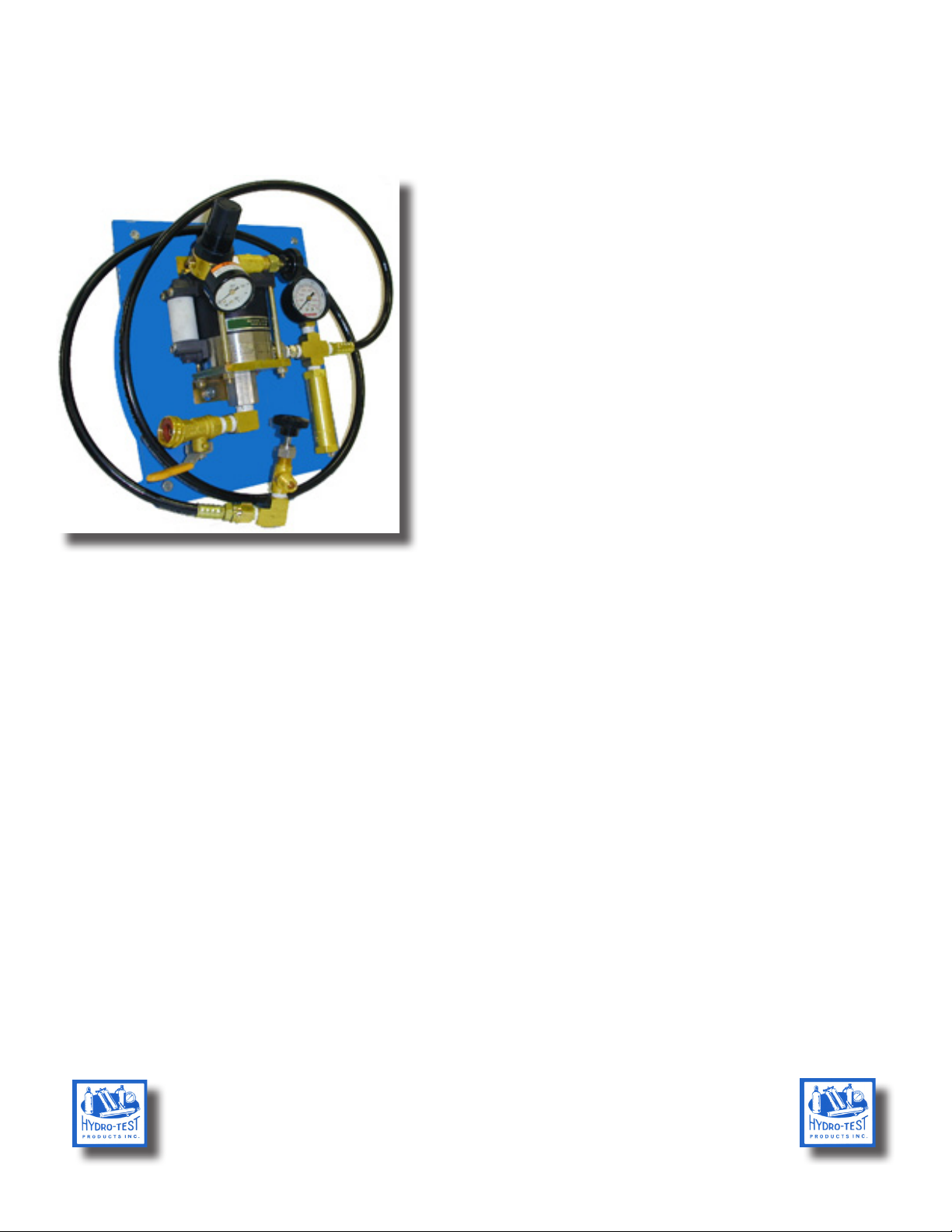
Air Operated Hydrostatic Proof Test Pump
Designed for performing a proof hydrostatic test on any
vessell in a test range of 0-1000 psi
Typically used for retesting re extinguisher cylinders,
small boilers, hoses, etc...
This is a piston driven pneumatic operated pump that
uses water as the test uid
This is a self lubricating pump - no external lubrication
or oil is required
Set Up
The model 500-801 requires the following utilities to operate:
• 100 psi @ 8CFM of pre-regulated shop air
• Inlet pressurized water supply (garden hose)
• Test adapters for vessell or cylinder being tested
• Mating quick disconnect ttings for end of hose and test adapters
The pump assembly is supplied on a steel base plate that can be either mounted on a wall or a bench
1) Connect your inlet air pressure hose to inlet of air regulator mounted on pump
2) Connect water supply to garden hose tting on pump,turn the ball valve at water inlet to the off position.
3) Prell the vessell or cylinder that is to be tested with water
4) Attach appropriate test adapter to the vessell or cylinder
5) Quick couple the hose to the test adapter
NOTE; the air supply must be PREREGULATED to no more than 150 psi BEFORE it goes into the air
regulator. Then you can adjust the black knob on top of air regulator so the regulator gauge reads 100 psi. To
adjust the regulator, rst pull up on the knob to unlock it, then turn the knob until the gauge reads a maximum
of 100 psi. On the right side of the pump is a hose with a tee on the loose end. The tee has two ports, one is a
high pressure bleed valve and the other is the connection for the vessel being tested. Now that you have the
water and air connected to the pump you are ready to start testing.
Hydro-Test Products Inc.
85 Hudson Road Stow, Massachusetts 01775
Tel: 800-225-9488 / 978-897-4647 Fax: 978-897-1942
www.hydro-test.com
Page 2
Basic Test Operation
1. Open the bleed valve at the tee
2. Open the incoming water ball valve on the pump
3. When the water starts to come out of the air bleed valve at the tee, close the air bleed valve
4. Turn the pump control valve on until you reach the proper test pressure
5. Close the water valve on the pump
6. Hold pressure for desired time
7. Open the bleed valve on the tee to relieve the pressure, observe gauge to be sure 0 pressure is indicated
8. Remove the adapter from the vessel
Important Note: ALWAYS HAVE THE VESSEL YOU ARE TESTING INSIDE AN APPROVED
SAFETY CAGE OR SHIELD. NEVER EXCEED THE TEST RANGE OF THE PUMP YOU ARE
USING . NEVER EXCEED THE RECOMMENDED TEST PRESSURE FOR THE VESSEL YOU
ARE TESTING.
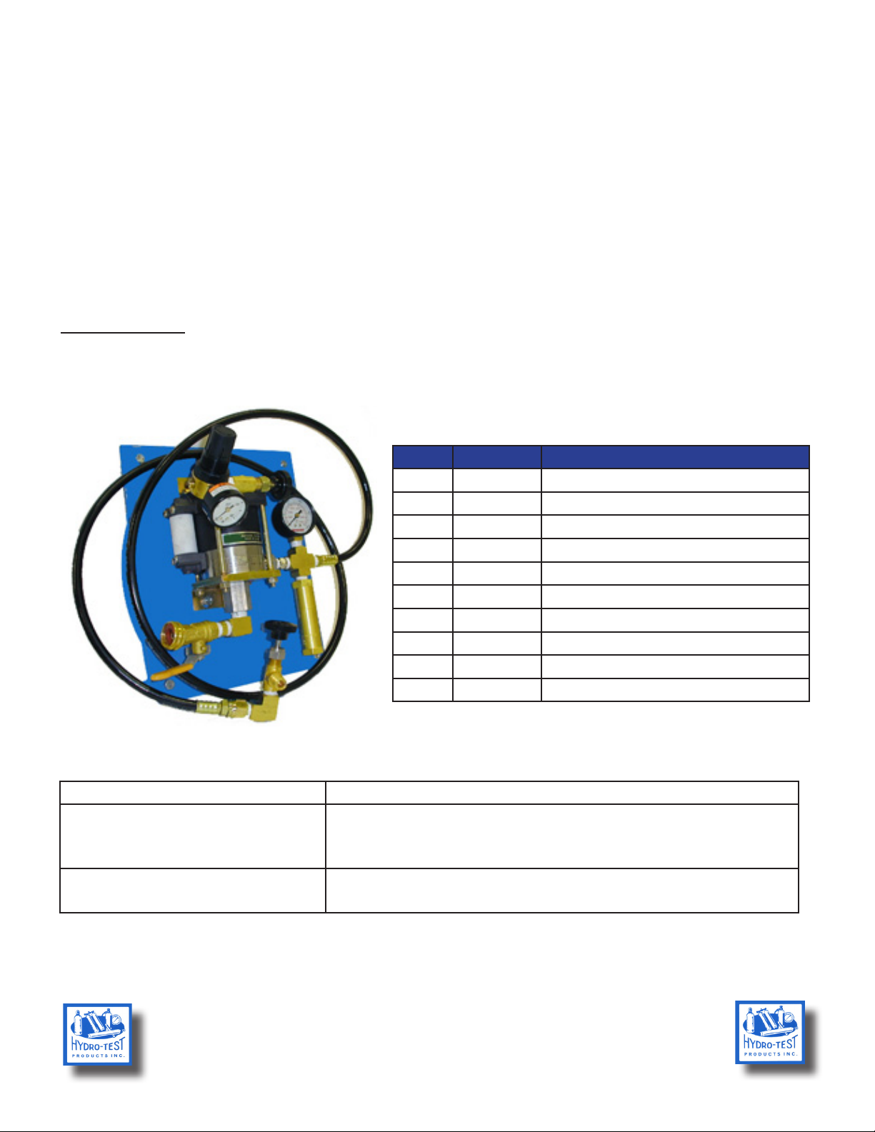
Parts Breakdown
A
C
B
J
I
H
F
G
Problem Cause / Solution
Pump does not build pressure
Pump does not hold pressure
Key Part No. Description
Inlet Air Regulator
Inlet Air Regulator Gauge
Pump Speed Control Valve
Outlet Pressure Gauge (1000psi)
Safety Relief Pressure Valve
Air/ Pressure Bleed Valve
Incoming Water Ball Valve
Inlet Water Connection (garden hose)
8’ Long Outlet Pressure Hose
Replacement Pressure Pump
D
E
A 160-010
B 160-013
C 120-034
D 140-009
E 120-018
F 120-034
G 120-004
H 220-018
I 200-100
J 190-030
Trouble Shooting
• Be sure air supply at regulator is 100 psi
• Check that vessell / cylinder is lled with water
• Check incoming water supply for blockage
• Check for physical leaks between pump and vessell / cylinder
• Outlet check valve on pump is faulty (consult factory)
Hydro-Test Products Inc.
85 Hudson Road Stow, Massachusetts 01775
Tel: 800-225-9488 / 978-897-4647 Fax: 978-897-1942
www.hydro-test.com
 Loading...