

Hydro-Temp VVV, VVH Installation Manual
Installation Manual
Models: VVV / VVH
Geothermal Heat Pump
• R-410A Refrigerant
• 2.5, 4.0, 6.0 Ton Variable Speed

Installation Manual 5.1.2
2

Installation Manual 5.1.2
TABLE OF CONTENTS
CONTACT INFORMATION: ................................................................................................................................................................. 4
MODEL NOMENCLATURE .................................................................................................................................................................. 5
1.0 TRANSPORTATION & STORAGE ................................................................................................................................................... 6
2.0 ELECTRICAL HAZARD WARNINGS ................................................................................................................................................. 6
3.0 HYDRO-TEMP SYSTEM INSTALLATION ......................................................................................................................................... 6
4.0 DUCTWORK CONSIDERATIONS .................................................................................................................................................... 7
5.0 DHW HEATING ............................................................................................................................................................................. 8
6.0 THE GROUND LOOP SYSTEM ...................................................................................................................................................... 14
8.0 CONDENSATE CONSIDERATIONS ............................................................................................................................................... 17
9.0 LOW & HIGH VOLTAGE CONNECTIONS ...................................................................................................................................... 17
10.0 PROTOSTAR THERMOSTAT CUSTOMER NAVIGATION INSTRUCTIONS ..................................................................................... 20
10.1 ZONE SENSOR / T-STAT ............................................................................................................................................................ 35
11.0 V-STAR INSTALLER SETTINGS. .................................................................................................................................................. 36
12.0 SYSTEM SEQUENCE OF OPERATION FOR FULLY VARIABLE V-STAR WITH PROTOSTAR THERMOSTAT ...................................... 42
13.0 RECOMMENDED HYDRO-TEMP™ START-UP PROCEDURE ........................................................................................................ 44
14.0 PREVENTATIVE MAINTENANCE ................................................................................................................................................ 45
15.0 BASIC TROUBLE SHOOTING CHART FOR THE HYDRO-TEMP SYSTEM ........................................................................................ 48
Explanation of Terms / Acronyms used in Manual
AWG = American Wire Gauge
DHW = Domestic Hot Water
AHW = Auxiliary Hot Water
CFM = Cubic Feet per Minute
UV = Ultra Violet
Vac = Volts Alternating Current
Vdc = Volts Direct Current
BAS = Building Automation System
VA = Volt Amps
GPM = Gallons per minute
PVC = Polyvinyl Chloride
CPVC = Chlorinated Polyvinyl Chloride
Relay reference to C = common terminal
Relay reference to NO = Normally open terminal
Relay reference to NC = Normally closed terminal
E-Heat = Emergency heat / strip heat only, compressor locked off.
Aux heat = Auxiliary heat / strip heat running with compressor.
3

Installation Manual 5.1.2
All rights reserved
Hydro-Temp™ Corporation has compiled this manual with care; however Hydro-Temp™ does not warrant that the
information in this manual is free of errors. Hydro-Temp™ reserves the right to change any portion of this manual without
notice. The appearance of any technical data or editorial material in this manual does not constitute endorsement,
warranty, or guarantee by Hydro-Temp™ of any product, service, process, procedure, design, or the like. The user assumes
the entire risk of the use of any information in this manual.
Contact Information:
Hydro-Temp™ Corporation
P.O. Box 566
3636 Hwy 67 South
Pocahontas, AR 72455
870-892-8343
www.Hydro-Temp.com
Do not install, operate, or maintain this equipment before carefully reading this instruction manual. Additional copies of
this manual are available from the installing dealer or from Hydro-Temp™ Corporation.
Save these and any other operating instructions for yourself and any future owners of this equipment.
A trained Hydro-Temp installer must perform all installation practices.
A licensed refrigeration technician must perform all refrigeration repairs / modifications. Hydro-Temp must approve all
service repairs if system is covered under manufacturer warranty.
Installation Manual Print Date: April 27, 2015
4
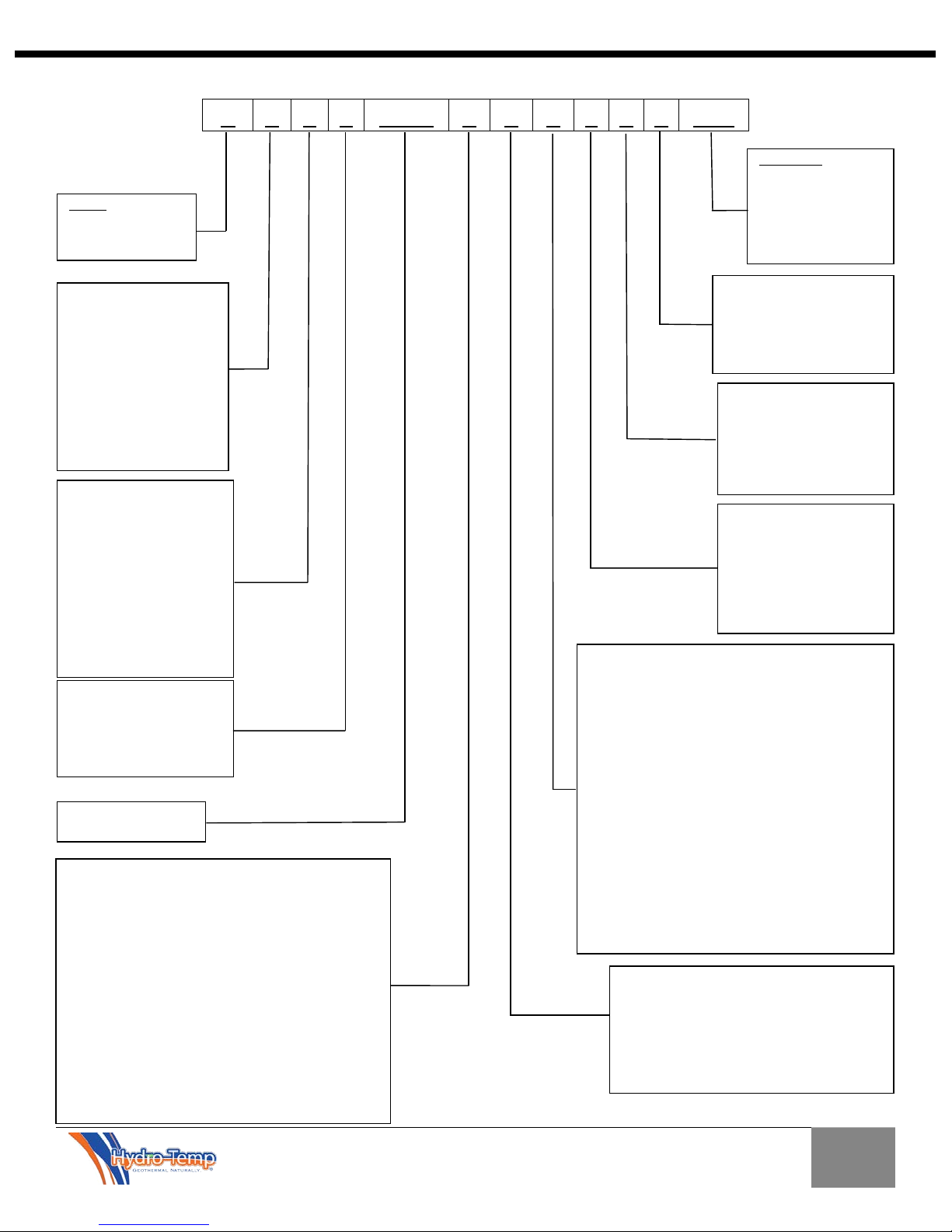
V X X 1 XXXX
X X X 1 X X XXX
SERIES:
V = V-STAR
UNIT BTU OUTPUT:
CONFIGURATION:
COMPRESSOR SPEEDS:
X = NON-APPLICABLE
AIR FLOW DIRECTION:
O = END RETURN & SUPPLY – RIGHT RETURN, LEFT SUPPLY
WATER SOURCE:
STRIP HEAT:
REFRIGERANT:
X = IF NON-APPLICABLE
Microprocessor:
4 = END USER DDC
VOLTAGE/PHASE:
HOT WATER OPTIONS:
COMPACT MODELS
WATER PLUMBING LOCATION:
X = NO WATER/UNKNOWN PLUMBING LOCATION
C = COMMERSIAL
R = RESIDENTIAL
A = SINGLE SPEED
B = TWO SPEED
C = THREE SPEED
D = FOUR SPEED
E = FIVE SPEED
F = SIX SPEED
G = SEVEN SPEED
H = EIGHT SPEED
M = MULTI-SPEED
V = VARIABLE
Installation Manual 5.1.2
MODEL NOMENCLATURE
XXX = NO STRIP HEAT
005 = 5KW
010 = 10KW
015 = 15KW
020 = 20KW
OR TOTAL KW
W = OPEN LOOP/WELL WATER
C = CLOSED LOOP
T = COOLING TOWER
X = IF NON-APPLICABLE
X = TERMINAL STRIP
1 = GEORGIA
CONTROL/HYDRO-TEMP
2 = AUTOMATED LOGIC/583
3 = AUTOMATED LOGIC/6126
C = CORNER CONSOLE
H = HORIZONTAL
L = LONG CONSOLE
N = NARROW CONSOLE
O = COMPACT HORIZONTAL
P = COMPACT VERTICAL
R = ROOF TOP
S= SPLIT
V= VERTICAL
W = WATER TO WATER
F = COUNTER FLOW
1 = R410A
2 = R22
3 = R134A
4 = R407C
BTU X 1000
X= Unknown at the time of submittal
A = UPFLOW-RIGHT RETURN
B = UPFLOW-LEFT RETURN
C = UPFLOW-BACK RETURN
D = UPFLOW-TOP RETURN
E = UPFLOW FRONT (CORNER CONSOLE ONLY)
F = HORIZONTAL FLOW-RIGHT RETURN
G = HORIZONTAL FLOW-LEFT RETURN
H = HORIZONTAL FLOW-BACK RETURN
I = HORIZONTAL FLOW/ FRONT
J = COUNTER FLOW-RIGHT RETURN
K = COUNTER FLOW-LEFT RETURN
L = COUNTER FLOW-COUNTER RETURN
M = COUNTER FLOW-BACK RETURN
N = END RETURN & SUPPLY – LEFT RETURN, RIGHT SUPPLY
1 = 208/230Vac-1 PHASE
2 = 115Vac-1PHASE
3 = 208/230Vac-3 PHASE
4 = 460Vac-3 PHASE
5 = 575Vac-3 PHASE
6 = 265/277Vac-1 PHASE
7 = 380Vac- 3 PHASE
X = NO HOT WATER
B = DESUPERHEATER AND INFLOOR*
C = DESUPERHEATER AND POOL HEATING*
D = DESUPERHEATER
E = HYDROZONE AND DESUPERHEATER*
F = HYDROZONE AND INFLOOR*
G = HYDROZONE AND POOL HEATING*
H = HYDROZONE
I = INFLOOR
J = INFLOOR AND POOL HEATING*
O = DHW PRIORITY AND HYDROZONE*
P = DHW PRIORITY
Q = DHW PRIORITY AND INFLOOR*
R = DHW PRIORITY AND POOLING HEATING*
S = POOL HEATING
(SELECT ONLY ONE)
*THIS OPTION IS NOT AVAILABLE IN CONSOLE OR
R = WATER THROUGH RIGHT SIDE
L = WATER THROUGH LEFT SIDE
B = WATER THROUGH BACK
C = WATER THROUGH BOTTOM
T = WATER THROUGH TOP
F = WATER THROUGH THE FRONT
5
Installation Manual 5.1.2
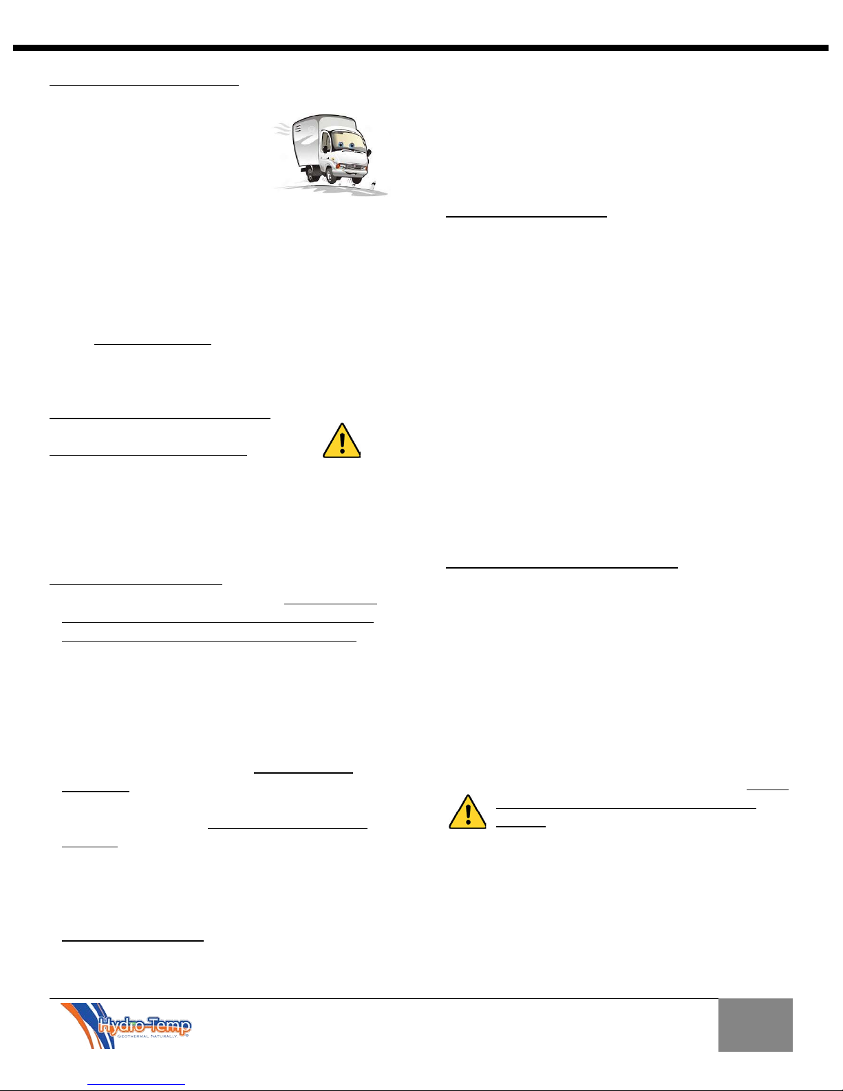
1.0 Transportation & Storage
Move and store units in an
upright position. Do not stack
units. Inspect shipment for
shipping damage and check
packing slip for accuracy. Any
equipment or cartons in question should be removed
from the packing and physically inspected. If any
damage is detected, the carrier should make a note on
the delivery slip acknowledging the damage. In some
cases smaller items like thermostat or temperature
sensors will be packed and shipped inside the system.
During freezing conditions special consideration should
be made to prevent unit damage. If a unit is taken to
the job site or put in storage, anti-freeze will need to
be pumped into the water coils to prevent freezing.
Failure to do this will void warranty.
2.0 Electrical Hazard Warnings
THE FOLLOWING IS A GENERAL WARNING
STATEMENT WHICH SHOULD BE READ AND
UNDERSTOOD BEFORE INSTALLING AND OR
OPERATING YOUR NEW HYDRO-TEMP UNIT
ELECTRIC SHOCK CAN KILL!!
• Always protect yourself and others. Always turn off
system power before removing panels. Some units
may have more than one or two power supplies.
• Keep all covers and panels in place at all times. When
removed for install or service purposes never leave
the cover off when left un-attended.
• Do not stick hands into return or any other opening.
• All repairs, electrical or mechanical, should be
attempted only by trained Hydro-Temp technicians.
In the event of a unit problem, do not reset the
equipment before correcting the problem.
Equipment failure due to resetting without first
correcting the problem will not be covered by the
warranty.
• The presence of water around the base of the unit
constitutes an electrical hazard. Turn off the power
to the unit as soon as water leakage is discovered and
call a service technician immediately.
• STRIP HEAT WARNING: On systems with
auxiliary/emergency heat strips, be aware that the
heat strip contactor may be wired on a separate
circuit. Therefore an additional breaker must be shut
off before removing panels and servicing unit.
• All breakers/fuses supplying power to this equipment
should be clearly labeled at time of installation.
• All wiring and plumbing should be done in strict
accordance with local and national codes and
ordinances.
2.1 Electrical Connections
Power to the Hydro-Temp System and back-up
electric heater may be two or sometimes three
circuits (Some large dual compressor systems will
require a circuit per compressor). A standard system
requiring one circuit for compressor and one circuit
for strip heat can be wired with 2 breakers in the
main breaker panel or one circuit feeding a sub
breaker panel near the system. All circuits must have
its own power disconnect near the system. The
electrical installation must be performed by a licensed
electrician, except for the low voltage wiring (Class 2)
(i.e. T-Stat) which can be done by the heat pump
contractor. Note: In most areas high voltage can be
taken from disconnect to the unit by the mechanical
contractor if allowed by local codes. All wiring and
plumbing should be done in strict accordance with
local and national codes and ordinances.
3.0 Hydro-Temp System Installation
Locate the unit in a conditioned, indoor area that allows
for easy servicing. Make sure that the air filter access
and unit access panels are easily accessible. Provide
sufficient room to make all ground loop, well water,
DHW, condensate, electrical, and if applicable
refrigeration connections.
If the unit is placed in a closet, make provision for
adequate return air flow to the unit.
Some installations may require a condensate pump to
take the condensate to a suitable drain location. Do not
locate the unit in an area that is subject to
freezing. The minimum recommended room
temperature for equipment location is 60°F. Provide a
heated, insulated enclosure for the unit where
necessary.
6
Installation Manual 5.1.2
4.0 Ductwork Considerations
Important Note: If ductwork is installed in an attic
area, it needs to be built “low profile” and laid directly
on the ceiling joist. After being installed and insulated
with R6 insulation, it must be covered with six to eight
inches of cellulose. If the attic ductwork is not covered
with cellulose it can lose a significant amount of its
heating and cooling capacity!!
Inadequate ductwork will cause poor system
performance and customer dissatisfaction. In the USA,
ductwork sizing methods should follow ACCA “Manual
D”.
Install ductwork within the conditioned space of the
building to minimize duct heat loss or gain, wherever
possible. To minimize air velocity noise transferring to
the air supply grills, flex duct should be installed from
the supply grill back six feet.
Vstar systems will ramp the compressor as needed to
maintain heating or cooling set point. The CFM
delivered by the system will initially ramp up equal to
400 CFM / ton in heat or 375 CFM / ton in cooling.
After the Vstar system has run for a few minutes the
blower will adjust slightly in an attempt to maintain
discharge air temp set point. Default discharge air set
points are 55ºF in cooling and 100ºF heat.
Ductwork should be designed to handle CFM delivery
for the system while running in High Speed. Supply duct
should be based on .08 inches of pressure drop per 100
feet. Return duct should be based on .05 inches of
pressure drop per 100 feet.
Note: Always check register CFM requirements against
register manufacturer’s data for register performance.
It is extremely important to ensure that duct system
return air is NOT undersized. Undersized return air can
cause poor system performance and in some cases can
cause the blower to “pulse”. Further, it is also
important to provide adequate sized supply air
plenums. Make all turns as smooth as possible avoiding
any restrictions.
For residential design the target static pressure should
not be greater than 0.3”.
Caution: Observe the location where your
ductwork is being attached to the unit. Ensure
that drilling and screws do not damage the air coil.
4.1 Hydro- Temp System Noise and Vibration
Isolation
A quality installation should be one where noise is not a
complaint. A number of inexpensive features can be
added to reduce noise and also aid in installation and
maintenance. Flexible hose kits to the hot water loop
will make for easy connection to the heat pump and the
hot water tank and also reduce any noise being
transmitted from the heat pump to the indoor
plumbing. Next the heat pump and all associated water
pumps should be installed on a shock-absorbing pad to
isolate the heat pump from a hard surface floor. This
pad will help stop the possibility of the cabinet being
rusted out by trapped moisture under the unit. Flexible
duct connections help to stop noise from the heat
pump being transmitted through the metal ductwork.
This collar also makes the connection of the heat pump
to the ductwork a much simpler task. It is not
recommended to hang the Hydro-Temp unit from the
floor joist, but if this becomes necessary, adequate
isolation MUST be provided to reduce unit noise and
vibration from being transmitted to the rest of the
building.
4.2 Air Filtering
To maintain good indoor air quality in a tight building,
the air distribution system should have a high-efficiency
air filter. To ensure proper unit operation, be sure to
inform the building owner of the importance of proper
maintenance and the maintenance schedule for the
filter installed. Most air filters require monthly
attention. On the first of every month the “CK Filter”
button will appear on the main screen of the Protostar
thermostat as a reminder to clean or replace the air
filter. Press this button for instructions on how to reset
the filter indicator after the filter has be cleaned or
replaced. This feature can be turned off in the
customer settings.
4.3 Construction / Remodeling
The Hydro-Temp system should never be run during any
kind of construction or remodeling that would allow
drywall, hard wood, or any kind of dust to be pulled in
the system. Even with extra filtering dust particles can
accumulate in the duct system causing unwanted dust
7

for years to come. It can also cause air coil clogging,
condensate drain clogging, blower dust accumulation
and many other problems to the system. Running the
system during construction / remodeling will void the
system warranty.
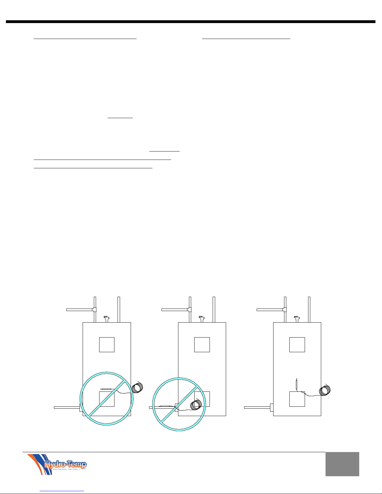
5.0 DHW Heating
There are two methods used by Hydro-Temp to heat
hot water. They are a standard desuperheater and ondemand priority hot water generation system. The
standard desuperheater utilizes a small desuperheater
coil as shown on the left of the picture, in-line with the
hot gas circuit to heat water any time the system is on
heating or cooling the space. The on-demand priority
method utilizes a much larger coil and a sensor
mounted on the DHW tank to monitor the tank
temperature. The on-demand priority method will heat
water any time the system is heating or cooling the
space, as well as starting the system as needed to heat
the DHW tank. When running to heat the DHW tank
alone, the blower will not run.
5.1 DHW Tank Preparation
If a hot water heating option is to be installed, electric
domestic hot water (DHW) tanks are regularly used,
although other fuel types are sometimes acceptable.
1. Turn off the power supply or the fuel supply to
the DHW tank.
2. Close the cold water supply valve to the DHW
tank.
3. Attach water hose to the tank drain connection
and empty the tank to a drain or outside.
4. Open the pressure relief valve or faucet nearby
to break the vacuum inside the water system to
speed up the draining process.
5. After the tank has been drained disconnect the
hose and remove the DHW tank drain fitting.
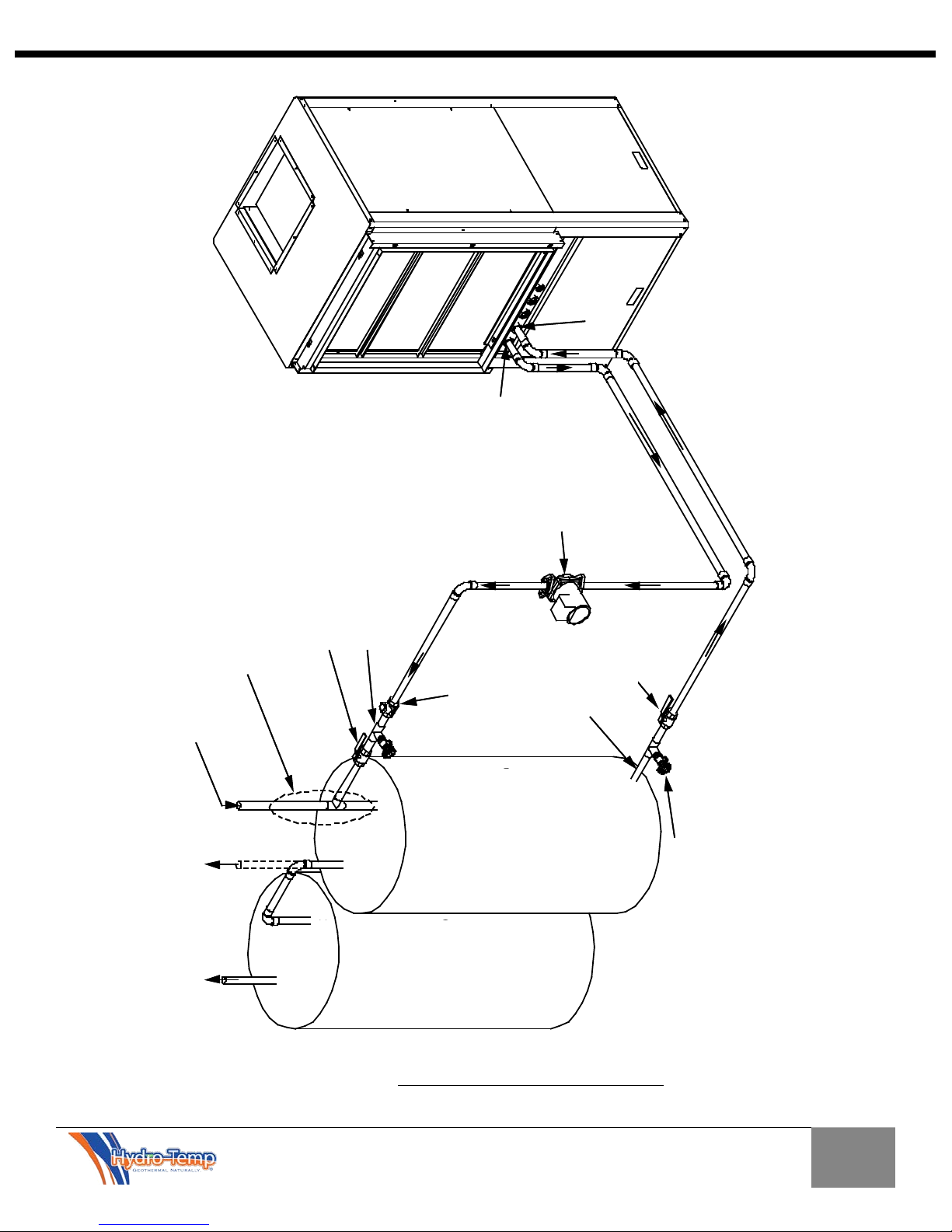
5.2 Desuperheater Option Installation (Only copper
tubing should be utilized)
Install the desuperheater circuit similar as shown in Fig.
5.2. Include isolation valves and two boiler drain valves
for tank draining and DHW system purging. Valves
allow for pump service without draining the DHW tank.
A horizontal swing check valve must be used to prevent
over heating of the tank. Use 1/2” copper tubing if up
to 30' tank distance. Over 30' adapt up to 3/4" copper
pipe for lower DHW pressure drop.
Installation Manual 5.1.2
Remove existing drain port from the hot water tank and
insert a standard dielectric fitting (thread the male end
of the fitting into the water heater drain port using a P.
T. F. E. based thread sealer) and continue with
installation as shown. Insulate all desuperheater circuit
piping with pipe insulation.
5.2.1 Dual tank Preheat method Hot water loop
hookup.
Figure 5.2 shows the dual tank preheat method. The
preheat tank (Tank 1) is not powered and is heated to
116 ºF solely by the Hydro-Temp unit. The second tank
(Tank 2) is powered but receives “heated” water from
the preheat tank. The second tank will only turn on
occasionally to replace its heat loss.
5.3 On-Demand Priority Hot Water Generation Option
Installation
(Only copper tubing should be utilized)
Install the priority hot water circuit similar to the
desuperheater circuit. Size the copper according to the
fittings on the Hydro-Temp unit. Install all insulation,
ball, and check valves as discussed with the
desuperheater system. The horizontal swing check
valve is critical on all priority systems to prevent over
heating of the DHW tank. Never use plastic fittings
(CPVC or Pex) when connecting between the tank and
the Hydro-Temp system. Only copper or brass should
ever be used. Failure to do so could result in damage
to system and home!
8
Installation Manual 5.1.2
Hot Water
Heater
INCORRECT
Hot Water
Heater
INCORRECT
Hot Water
Heater
CORR
ECT
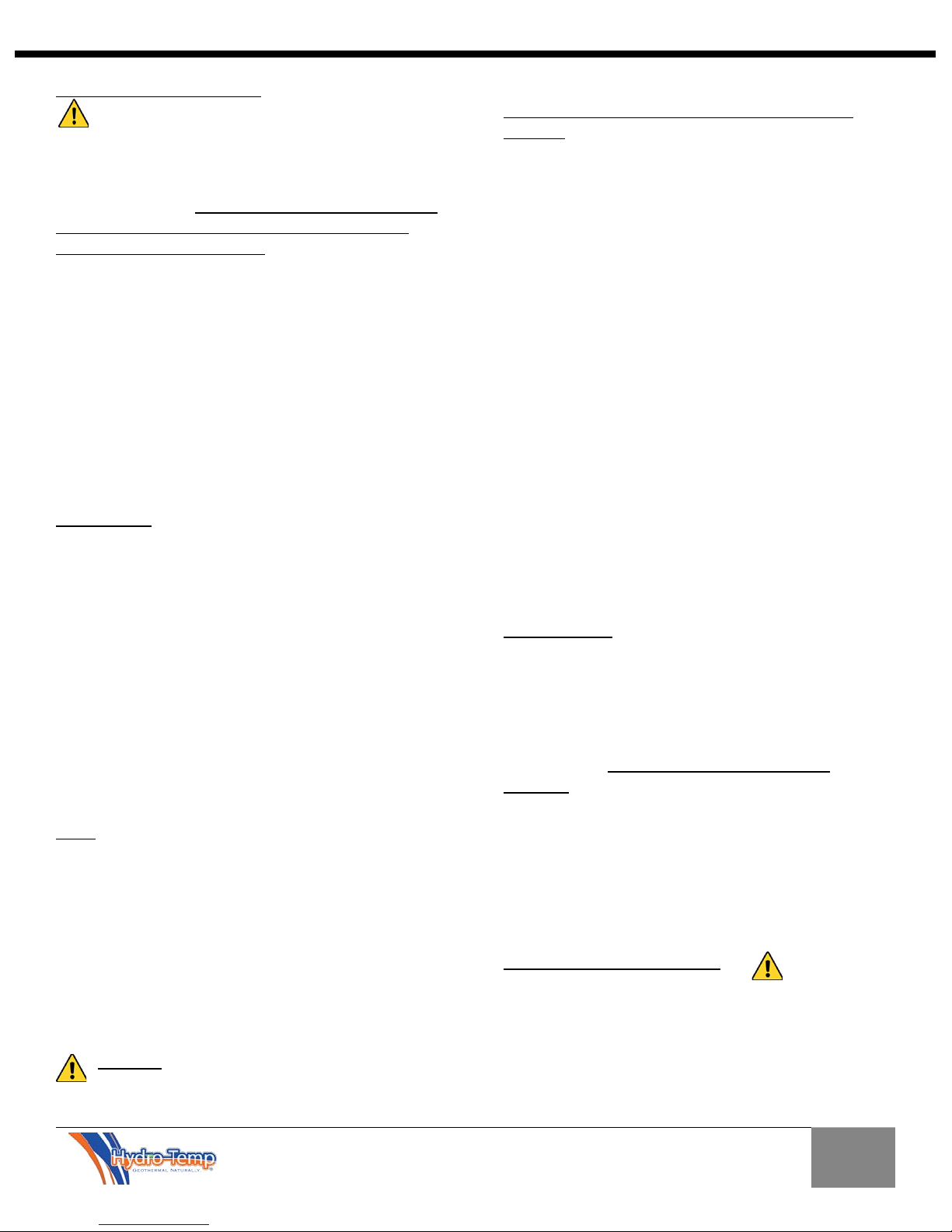
Figure 5.1 Sensor Placement
5.4 Priority Hot Water DHW Sensors
Systems with the on-demand priority hot water
generation will include a few extra sensors. Most
are internal to the system and require no field
installation. The domestic hot water tank sensor
must be mounted directly on the hot water tank.
This sensor will allow the Hydro-Temp unit to turn
on and off as needed to heat the hot water. The
sensor should be installed vertically above or beside
the bottom element between the steel tank and the
insulation as shown in the illustration below.
Vertical mounting provides proper surface contact
between the sensor and the round tank. The sensor
must be tight against the tank and well insulated.
Proper installation of the sensor is critical. If the
sensor were to come loose, the system could easily
overheat the tank, damaging the tank and/or the
Hydro-Temp system. After installation make
appropriate wiring connections to the Hydro-Temp
system. Wire the two legs of the sensor to the
terminal strip labeled “DHW Tank Temp”. HydroTemp provides a mounting bracket to aid in keeping
the DHW tank sensor in direct contact with most
conventional hot water tanks. The clip, installation
instructions, and DHW tank sensor will be shipped
in a small plastic bag with one of the two wires
connected to the terminal strip inside the electrical
box of the Hydro-Temp system. The other wire is
intentionally left loose so the system will recognize
no sensor is connected.
5.5 Marathon Hot Water Tanks
Marathon hot water tanks require a "special" bracket
which allows the DHW tank sensor to be placed in direct
contact with the tank's existing thermostat bracket. This
is required due to the fact the Marathon tank is made of
a polyethylene material that does not readily conduct
heat and will not allow accurate temperature
readings. This bracket, holding screw, and instructions
are enclosed in the plastic bag containing the DHW tank
sensor.
9
Installation Manual 5.1.2
Hot Water Out
(For 2 Tank System)
Ball Valve (Valve A)
Water OUT
Water IN
3/4" Hose Bib (Boiler Drain A for Purging)
Horizontal Swing
Check Valve
BRONZE Circulating
Pump mounted
vertical (Can be
Installed in either
Line)
Hot Water Tank (1)
or pre-heat tank in
the two tank installation
C
H
C
H
Optional
Hot Water Tank (2)
Hot Water Out
(For 1 Tank System)
All pipe fittings in this area MUST be Copper,
brass, bronze or Steel and must extend a
minimum of 12" above the "T" before
connecting to CPVC or PEX
Ball Valve (Valve B)
3/4" Boiler Drain B
(Used to drain tank only)
Cold Water In
Dielectric
Fitting
All copper piping must be the same size as the fittings on the Hydro-Temp
system. Under sizing this piping will reduce the gpm flow and can damage
the unit and void the warranty. If 1" copper is used it must be reduced to 3/4"
as close to the tank as possible.
Note: on long piping runs the copper piping may need to be "upsized" to
lower the pressure drop of the circuit.
Ball Valve (Valve A)
Water OUT
Water IN
3/4" Hose Bib (Boiler Drain A for Purging)
Horizontal Swing
Check Valve
BRONZE Circulating
Pump mounted
vertical (Can be
Installed in either
Line)
Hot Water Tank (1)
or pre-heat tank in
the two tank installation
C
H
C
H
Optional
Hot Water Tank (2)
All pipe fittings in this area MUST be Copper,
brass, bronze or Steel and must extend a
minimum of 12" above the "T" before
connecting to CPVC or PEX
Ball Valve (Valve B)
3/4" Boiler Drain B
(Used to drain tank only)
Dielectric
Fitting
All copper piping must be the same size as the fittings on the Hydro-Temp
system. Under sizing this piping will reduce the gpm flow and can damage
the unit and void the warranty. If 1" copper is used it must be reduced to 3/4"
as close to the tank as possible.
Note: on long piping runs the copper piping may need to be "upsized" to
lower the pressure drop of the circuit.
Figure 5.2 Hot Water Tank Only copper tubing should be utilized (H005672)
10
Installation Manual 5.1.2
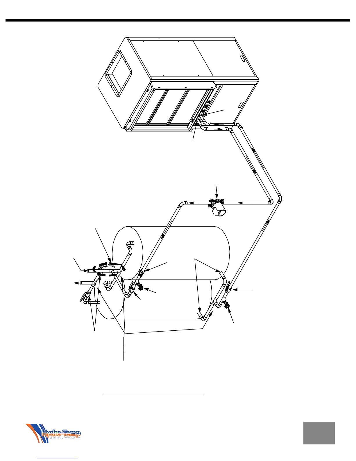
C
old Water In
Ball Valve
(Valve A)
Water OUT
Water IN
3/4" Hose Bib
(Boiler Drain
A for Purging)
Horizontal Swing
Check Valve
Ball Valve (Valve B)
3/4" Boiler Drain B
(Used to d rain tank only)
C
H
C
H
T1
T2
T3
Note: The 3 Tee's
labeled T1, T2 and T3
must be "
centere
d" to
ensure equal flow
from both tanks.
Hot Water Out
BRONZE Circulating
Pump mounted
vertical (Can be
Installed in either
Line)
All pipe fittings in this area MUST be Copper,
brass, bronze or Steel and must extend a
minimum of 12" above the "T" before
connecting to CPVC or PEX
All copper piping must be the same size as the fittings on the Hydro-Temp
system. Under sizing this piping will reduce the gpm flow and can damage
the unit and void the warranty. If 1" copper is used it must be reduced to 3/4"
as close to the tank as possible.
Note: on long piping runs the copper piping may need to be "upsized" to
lower the pressure drop of the circuit.
Dielectric Fittings
Tank Isolation Ball Valves
Figure 5.3 Dual Tank Hot Water Only copper tubing should be utilized (H005673)
11
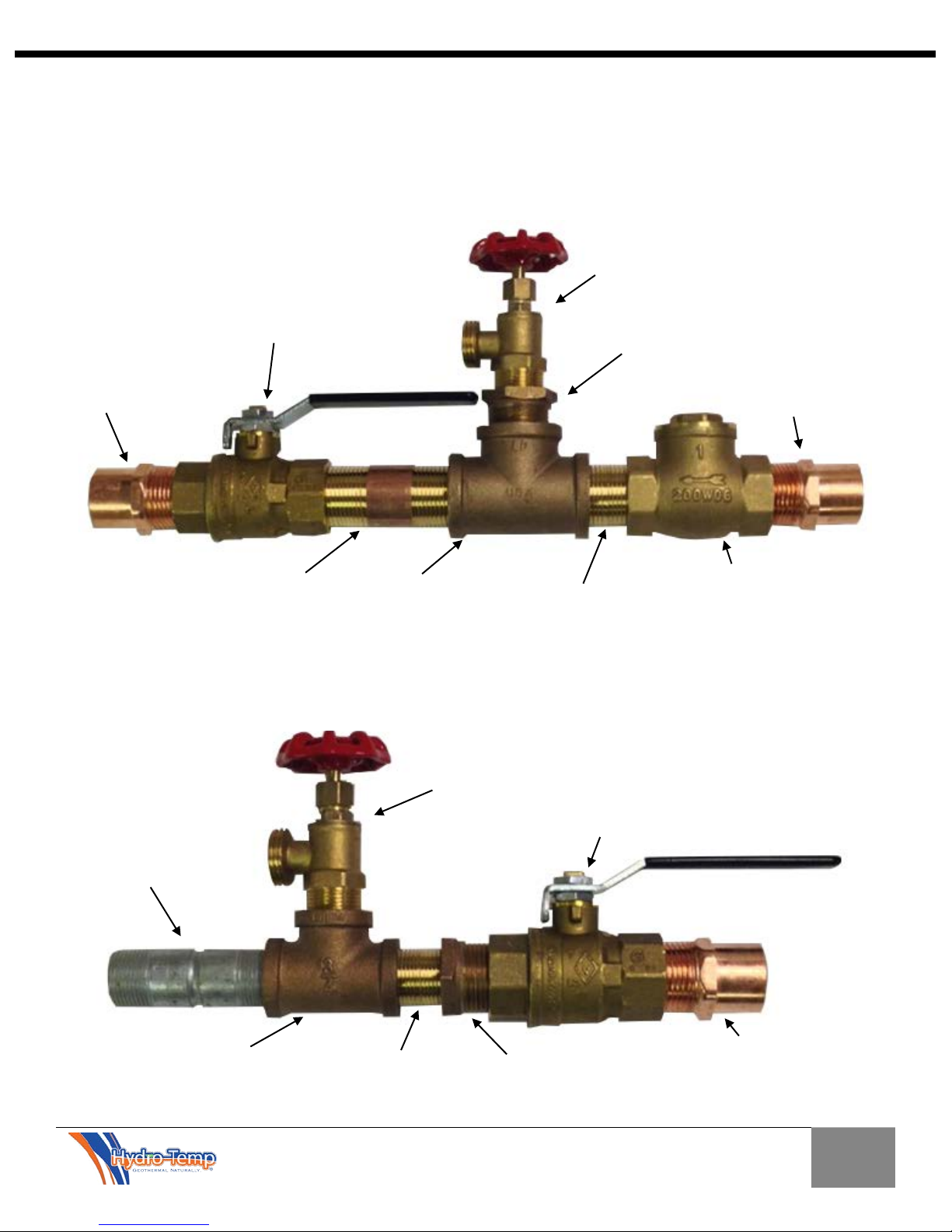
Installation Manual 5.1.2
1” Horizontal “swing”
1” Brass nipple
1” Brass nipple
1” Copper male
1” Brass “T”
Standard hose fitting / Boiler drain A
¾” x 1” brass
Standard hose fitting / Boiler
1” Full Port Ball Valve
¾” Dielectric nipple
1” Copper male
3/4” Brass “T”
1” Brass nipple
¾” x 1” brass
Figure 5.4
Figure 5.5
UPPER DHW Plumbing Fittings (connecting into cold water line on the top of the tank)
2.) No other water lines can be connected between the “T” and the tank.
LOWER DHW Plumbing Fittings (connecting into bottom of the tank)
water flow.
Refer to figure 5.2 and 5.3 for plumbing details
Refer to figure 5.2 and 5.3 for plumbing details
1” Copper male
1” Full Port Ball Valve
*Important: 1.) All fittings on the cold water line where the plumbing (below) connects to the
tanks cold water line must be either copper, brass, bronze, or steel from 12” above the “T” to the
tank.
with ¾” MPT
adapter (“T’s”
into cold water
line directly
above tank)
Valve A
threaded bushing
adapter
check valve
*Important: Most water heaters have ¾” fittings. It is important to increase pipe sizing to 1”
(3-6 Ton Priority water heating units) in as short a distance as possible in order to assure proper
drain B with ¾” MPT
(connects to
bottom of water
heater after boiler
drain is removed)
threaded bushing
Valve B
adapter
12
Installation Manual 5.1.2
5.6 Purging the air from the DHW System
All the air must be purged from the DHW lines before
the system can be run to make hot water. Improper
purging will result in air in the pump causing the pump
to cavitate and damage the pump. Systems are
shipped from the factory with biodegradable RV
antifreeze pumped into the desuperheater or priority
coils. If proper purging methods are followed this antifreeze will easily be purged from the system.
5.6.1 Filling the Hot Water Tank
Close boiler drain valves and the isolation valves to the
Hydro-Temp system. Open the cold water supply
feeding the DHW tank. Open a hot water tap in the
building and allow air to bleed out of tank. Alternatively
you can depress lever on the tank relief valve to remove
air trapped in the tank. Once the building plumbing is
purged it is important to purge the air that is remaining
in the Hydro-Temp system and plumbing between the
hot water tank and the Hydro-Temp system. Purging
the building plumbing even with the isolation valves
open to the Hydro-Temp system will not purge the air
from the Hydro-Temp system.
5.7 Setting Hot Water Temperature
Refer to the hot water section of the Protostar user
manual. Here you will find how to set the set points for
DHW (Domestic hot water) heating and AHW (Auxiliary
hot water) heating. Note: Auxiliary hot water heating
normally refers to “infloor” or “Pool” heating.
5.8 Plumbing to a Marathon Hot Water Tank.
When plumbing the Hydro-Temp hot water heating
system to a Marathon hot water tank you need to keep
a couple of things in mind. All fittings must be
mechanical fittings at the tank; due to the tank being
plastic you cannot solder or braze close to the tank. The
direction of flow in and out of the tank and plumbing is
the same as with a steel tank. Never use plastic fittings
(CPVC or Pex) when connecting between the tank and
the Hydro-Temp system.
Take note of sensor location. Please refer to section 5.5
for best sensor installation practice.
In some cases an adjustment to the desired
temperature must be adjusted due to the high R value
of the plastic tank, as mentioned in section 5.5
5.6.2 Purging the Hydro-Temp Hot Water Loop
Attach a hose to the boiler drain A (refer to figure 5.2)
and run the hose to a floor drain or outside. Close the
isolation valve B at the bottom of the DHW tank. Open
the isolation valve A at the cold-water inlet on the DHW
tank and allow the water to flow out the hose. Allow
the water to run for a few minutes while checking for
air leaving the drain hose. Once all of the air has been
purged, close isolation valve A and open the isolation
valve B. Allow the water to flow through the system and
out the hose. Run for approximately 5 to 10 minutes
while checking for air leaving the drain hose. To insure
no air is trapped anywhere, open both valve A and valve
B to allow flow both ways. Allow water to run for
approximately one minute. Once purging is complete,
close the boiler drain valve, remove the hose and
ensure that both isolation valves “A & B” are open.
Wiring to the DHW pump is normally left unwired in the
Hydro-Temp’s electrical box and tagged with the proper
reconnection location. This wire should only be hooked
up after the system is properly purged to prevent pump
damage.
13
6.0 The Ground Loop System
Pump
To Unit
From Unit
To Loop
From Loop
Auto-purge
Hydro-Temp
Flanged Shut off Valve
Kit
1" Purge Port on 3-Way
Valve. All 3 valves are the
same as discibed above.
This pipe is normally ran behind
Auto purge or through auto purge.
33" from here to base. Tank
can be cut here to fit in tight
spaces.
3 Way valve with purge port. Flow
direction can be determined by
indicator on valve stem. Flow can
be through any two directions or all
three directions.
IMPORTANT! Do NOT use PVC or CPVC piping on any
connections to your Hydro-Temp unit. The only
exception where PVC or CPVC piping may be used is on
the condensate lines.
6.1 Closed Loop Systems Plumbing
Closed loop systems will require a minimum of 3 G.P.M.
per ton if the ground loop is designed to maintain a loop
temperature above 32ºF and below 90ºF. If design
temperatures are outside of these temperatures more
flow will be needed.
On residential systems typically a pump is required for
each unit. The loop pump requirement will depend
upon the loop design for a given application. The
ground loop piping system must provide suitable access
for purging the outside loop and require isolation valves
for purging the inside plumbing including the system.
To properly purge a closed loop system, a minimum
velocity of 2 feet per second in every branch of the
ground loop must be achieved. The purge ports will also
be used for anti-freeze charging.
Installation Manual 5.1.2
LOOP AT ALL TIMES. FAILURE TO DO SO WILL FREEZE
THE SYSTEM AND CAUSE SEVERE DAMAGE TO THE
UNIT.
DAMAGE TO THE UNIT CAUSED BY THE FAILURE TO
MAINTAIN PROPER ANTIFREEZE LEVELS IS NOT
COVERED UNDER THE WARRANTY.
It is recommended to always mount the ground loop
pump vertically so air will not be trapped in the pump if
not properly purged. A dry or air locked pump will
quickly burn out.
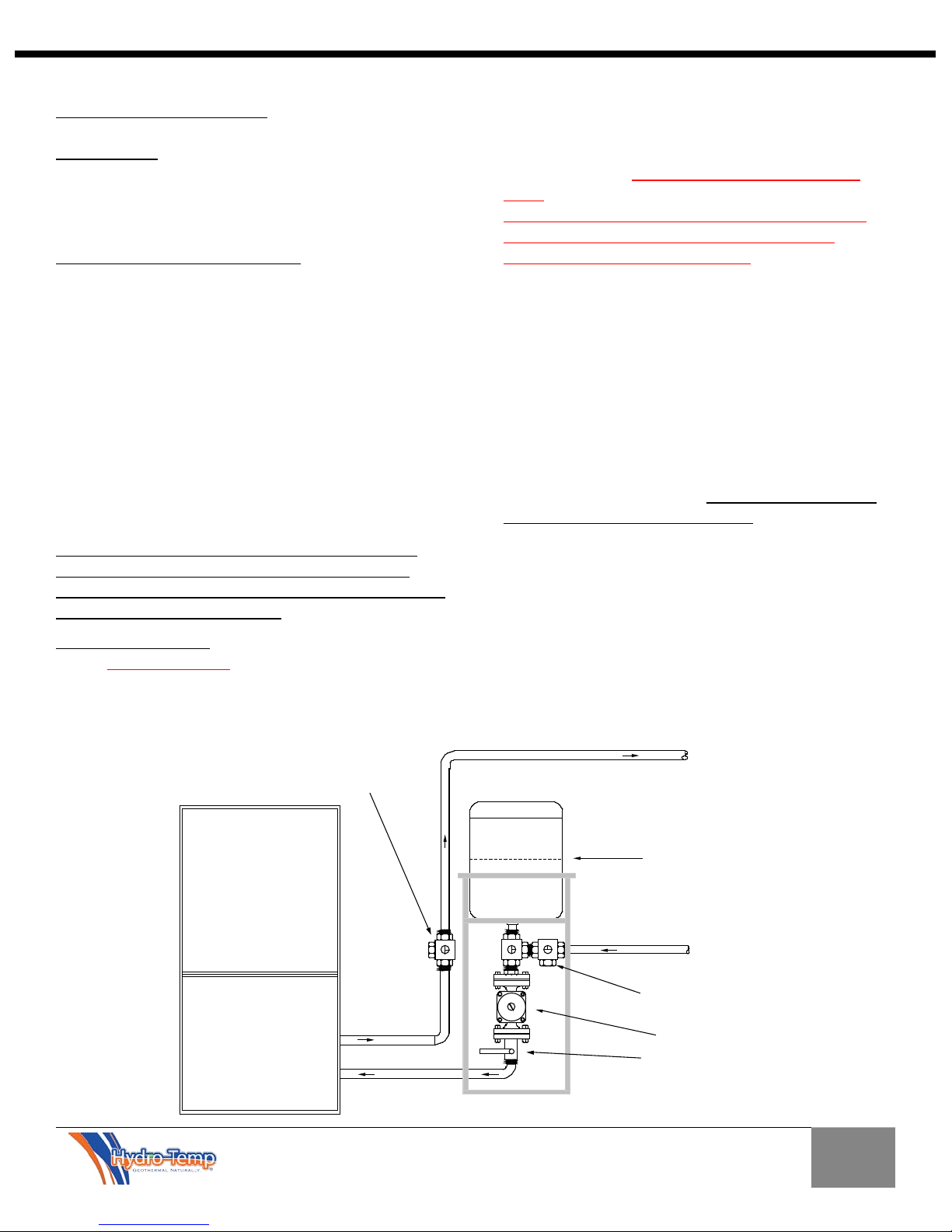
The recommended auto purge kit (shown below) is
designed with the pump mounted vertically and tees
strategically placed to purge air from the system and
into the auto purge tank automatically while running
(this should be used to remove small amounts of air left
after purging the system with the purge pump, or a
system pump replacement). The auto purge kit is not
used in place of purging the system but is left on the
system to purge the loop continuously. Systems with
the auto purge kit are not pressurized.
IMPORTANT NOTICE: UNITS THAT UTILIZE GROUND
LOOPS MUST MAINTAIN A MINIMUM OF 20%
METHANOL OR 25% PROPYLENE GLYCOL AS
ANTIFREEZE SOLUTION IN THE UNIT AND GROUND
14
Installation Manual 5.1.2
H
y
d
r
o
-
T
em
p
A
u
t
o
P
u
r
g
e
k
i
t
m
o
un
t
ed at
h
ig
h
es
t
p
oi
nt
Loo
p I
n
Loop
Out
Ho
riz
ontal Swing
Che
ck
Valve
Hyd
ro-
Tem
p
Loo
p I
n
Loo
p Out
H
orizon
tal Swin
g
Ch
eck Val
ve
Wat
er In
Water
Out
Auto-purge
Kit
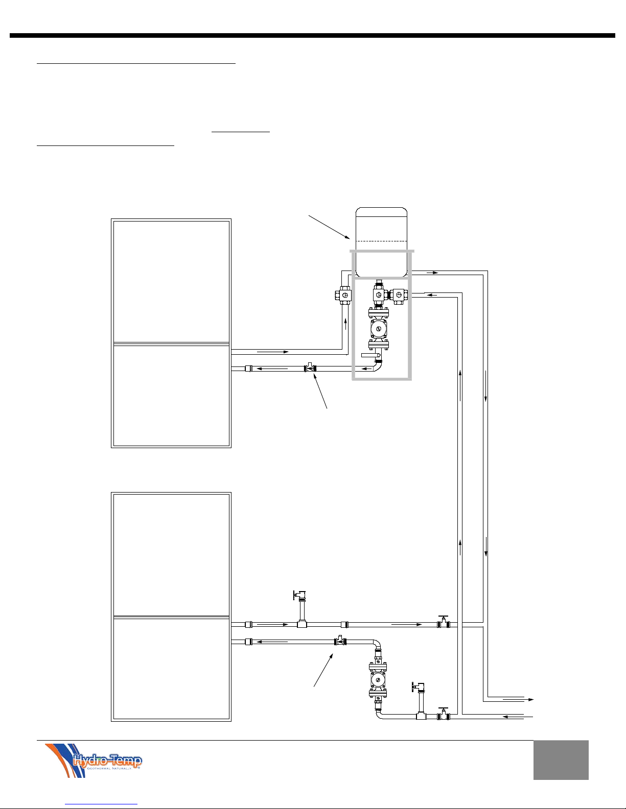
6.2 Closed Loop with two or more Systems
When two or more units are connected to one loop,
ONLY ONE auto purge kit is used. It is best if installed
on the highest unit at the highest point but does not
have to be higher than the loop field. Check valves
must be installed on each unit to prevent backward
water flow when the unit is off. The auto purge keeps
proper pressure on the suction side of the pump to
prevent air locking or cavitation from occurring. The
tank must be kept ½ to ¾ full at all times. As shown in
the drawing below, the other unit(s) simply need to
have a pump for each unit.
15
 Loading...