

Hydro Tek CPK, SK, HG, SR, ST Operation & Maintenance Manual
...
$15.00
OPERATION & MAINTENANCE
MANUAL
IMPORTANT: CAUTION! TO REDUCE RISK OR
INJURY, READ OPERATING INSTRUCTIONS
CAREFULLY BEFORE USING
POWER WASHERS
CPKSERIES
HG SERIES
SH SERIES
SK SERIES
SR SERIES
ST SERIES
© 2007 Hydro Tek

2
To get the best use of your pressure washer, please read the manual carefully. It contains all the
information necessary for you to operate the unit safely and to get the maximum benefit. This manual
also contains many helpful hints about pressure washer mainenance.
Tthe following additional accessories can be purchased to make your equiment more flexible for a
cleaning effort that is swift and efficient.
ACCESSORIES
TURBO
NOZZLE
ADJUSTABLE
PRESSURE WAND
CHEMICAL
INJECTORS
SAND
BLASTING
HYDRO TWISTER
SURFACE CLEANERS
HOSE
EXTENTIONS
HOSE
REELS
Servicing your Pressure Washer
Should you have any questions or are unable to resolve a problem after using the
Troubleshooting section of this manual, call Technical Support at: (909) 799-9222 7:30 – 4:00 PST.
The Techinical Support department can solve many problems over the phone. Please have the
following information available before calling:
* The pressure washer model number: _______________________
(on the product label)
* The serial number: _______________________
(located at the base of the machine)
* The purchases date from your purchase receipt (required for warranty service).
* A description of the problem.
Ordering Parts and Accessories
To order parts and accessories for your pressure washer, call or visit your local dealer.

TABLE OF CONTENTS 3
INTRODUCTION ............................................................................................................................... 4
Statement of Warranty
SAFETY WARNINGS ....................................................................................................................... 5
Electrical Precautions
Fire Precautions
Ventilation Precautions
Spray Injection Precautions
Personal Hazard Precautions
OPERATING INSTRUCTIONS ....................................................................................................... 6
Before Start Up
Operation
Shut Down & Antifreeze Protection
SYSTEM INFORMATION ................................................................................................................. 7
Power System
Electric Motor/Gasoline Engine
Power Transmission System - direct, & belt drive
Generator - circuit breaker
Pumping System ........................................................................................................................ 8
Pump
Unloader, Pressure Relief Valve and Burst Disk
Chemical Injection System - inlet & downstream injection
Water Supply - direct, float tank, & supply tank feed
Heating System ..........................................................................................................................9
Coil/Heat Exchanger System - temperature & flow switch controls
Diesel Fired Burner - air band, transformer, fuel pump, filter, & solenoid
Pressure Delivery System .........................................................................................................9
Discharge Hose, Hose Reels
Gun/Wand Assembly - trigger gun, wand, & quick coupler
Nozzles - spray nozzles, steam nozzle and turbo nozzle
Hydro Twister
Trailers
TROUBLE SHOOTING GUIDE .......................................................................................................12-15
WIRING DIAGRAMS ......................................................................................................................... 16-22
SERVICE RECORD.............................................................................................................................23
SERVICE/MAINTENANCE INFORMATION ................................................................................ 24
TEST SPECIFICATIONS ............................................................................................................. Enclosed
ENGINE SHEET ............................................................................................................................ Enclosed
PARTS LIST / EXPLODED VIEW .............................................................................................. Enclosed
USE ONLY CERTIFIED ORIGINAL EQUIPMENT REPLACEMENT
PARTS, FAILURE TO DO SO COULD LEAD TO WARRANTY
EXCLUSION AND SEVERE BODILY INJURY

4 INTRODUCTION
INTRODUCTION:
The employees and management of HYDRO TEK
thank you for selecting our products. The production and
quality assurance personnel have taken the greatest care in
the assembly process to ensure that your new High Pressure Cleaner is of a quality and standard acceptable to both
you the customer and us the manufacturer.
This operators manual was compiled for your benefit.
By studying and following the safety, installation, operation, maintenance, and troubleshooting information contained within, you can look forward to many years of
trouble free service from your equipment.
Upon receipt of the equipment, please inspect for any
concealed freight damage. Should you find damage has
occurred during shipping, do not return the damaged
merchandise to Hydro Tek, but file a claim immediately
with the freight carrier involved.
Please locate the enclosed warranty registration card.
Fill out and return it to activate the warranty on your
machine. Also enclosed are installation instructions.
Please note that the owner/user has certain obligations
under the terms of the warranty for this equipment, and as
such you are encouraged to always have every person who
will operate the equipment, read and become familiar with
the contents of this owners manual, prior to their using this
equipment.
Contact your AUTHORIZED HYDRO TEK DEALER
or a trained HYDRO TEK service engineer if problems
occur, or if installation is required.
THERE ARE NO USER SERVICEABLE COMPONENTS ON THIS EQUIPMENT.
The equipment is shipped with the fuel tanks empty, the
battery cables disconnected, and the pump antifreezed.
If you did not order a battery with your unit see page 5 for
battery requirements and instructions.
V-LINE LIMITED PARTS WARRANTY:
Hydro Tek warranties the Hydro Boss line and Hot2Go line
power washers to be free from defects in material and workmanship for one (1) year, calculated from the date of the original retail
purchase. Hydro Tek accessories are warranted for a period of 90
days from the date of their original purchase. Hydro Tek will make
the required repairs, or at Hydro Tek's option provide replacement
components if found to be defective by the reasonable judgement
of Hydro Tek. This warranty only extends to the original retail
purchaser, and is subject to the exclusions shown below. Any parts
replaced under this warranty will assume the remainder of the parts
warranty period.
This Warranty does not apply to and Hydro Tek is not
responsible for:
1 . Normal wear items such as Unloader Valves, Discharge
Hoses, Guns, Wands, Nozzles, Quick Couplers, Brushes,
Filters, Belts, Seals, O-rings, and Packings.
2. Labor charges or costs related to the removal of the
defective part, field labor charges, transportation to service
ONE YEAR LIMITED PARTS WARRANTY- Provided
by Hydro Tek, excluding normal wear items listed
below. Labor excluded.
ONE YEAR WARRANTY ON ENGINES & ONE YEAR
OR LESS ON ELECTRIC MOTORS - Up to two year
limited warranty provided by the respective engine
manufacturer and up to one year by electric motor
manufacturer. Labor excluded.
ONE YEAR COIL WARRANTY - one year parts
warranty. Labor, freezing & descaling excluded.
ONE YEAR PUMP WARRANTY- Up to one year
limited warranty on crankcase of the pump provided by
the respective pump manufacturer. Labor excluded.
center and costs to return it to Hydro Tek, or service
charges for scheduled maintenance or any adjustments.
3 . Damage due to freezing, abrasive fluids, chemical deteriora-
tion, and scale build up.
4 . Damage from fluctuation in electrical or water supply.
5 . Damage resulting from failure to follow
manufacturers maintenance instructions.
6 . Damage resulting from misuse, neglect, accidents, modifi-
cations, alterations, abuse, or incorrect installation.
7. Products operated outside of specified limits or intended
use as specified in the operation manual.
8. Repairs made necessary by the use of parts which are
either not obtained from or approved by Hydro Tek.
9 . Actions or inactions by any Hydro Tek distributor giving rise
to or causing a warranty exclusion or promise of additional
warranty.
10. Warranty on engines, motors, and pumps, which are war-
ranted by their respective manufacturers and are serviced
through the manufacturer's service centers.
LIMITATION OF LIABILITY
Hydro Tek's responsibility with respect to claims is limited in
making the required repairs or replacements, and no claim of
breach of warranty shall be cause for any cancellation or recision
of the contract of sale of any Hydro Tek product. Hydro Tek
reserves the right to change or improve the design of any of its
products or illustrations without assuming any obligation to
modify any product previously manufactured.
THERE IS NO OTHER EXPRESSED WARRANTY.
This supersedes any and all previous warranty statements for
products purchased after January 1, 2007. Hydro Tek is not liable
for indirect, incidental or consequential damages including but
not limited to: The cost of substitute equipment, loss of revenue,
pecuniary expense or loss, or any damages whatsoever arising
out of the use or inability to use a Hydro Tek product. Hydro Tek
disclaims all implied warranties, including those of merchantability and fitness for use or a particular purpose. It is the buyer's
responsibility to ensure installation and use of Hydro Tek products conforms to local codes. Proof of purchase date required to
obtain warranty. Complete warranty information is contained
on the warranty card and supersedes all information on this page.

IMPORTANT SAFETY WARNINGS: SAVE THESE INSTRUCTIONS 5
4. AVOID contact with the exterior of the coil/heat exchanger assembly,
exhaust stack and mufflers to prevent burns.
5. DO NOT store fuel or other flammable materials near the burner or any
other open flame.
6. To avoid burns NEVER stand over burner exhaust outlet or in front of
engine exhaust. Burner may start at any time once power is turned on.
7. Do not touch burner exhaust port, mufflers, or wands/hoses as
ELECTRICAL PRECAUTIONS:
1. Observe all State, Local, and National codes for the installation of your electrically powered washer.
2 . For a grounded product rated 250 volts, single phase, or less:
This Product Is Provided With A Ground Fault Circuit Interrupter Built Into The Power Cord Plug. If Replacement Of The
Plug Or Cord Is Needed, Use Only Identical Replacement
Parts.
3. GROUNDING INSTRUCTIONS:
Cord Connected, Grounded Products:
This product must be grounded. If it should malfunction or
breakdown, grounding provides a path of least resistance for
electric current to reduce the risk of electric shock. This product
is equipped with a cord having an equipment-grounding conductor. The plug must be plugged into an appropriate outlet that is
properly installed and grounded in accordance with all local
codes and ordinances.
Danger - Improper connection of the equipment-grounding
conductor can result in a risk of electrocution. Check with a
qualified electrician or service personnel if you are in doubt as
to whether the outlet is properly grounded. Do not modify the
plug provided with the product, do not cut off the ground pin
- if it will not fit the outlet, have a proper outlet installed by a
qualified electrician. Do not use any type of adaptor with this
product.
4. To comply with the national electric code, this pressure
washer should only be connected to a receptacle that is
protected by a ground fault circuit interrupter (GFCI).
5. EXTENSION CORDS:
Use of extension cords is not recommended.
6. NEVER operate an electrically powered washer after it has
tripped a breaker or a ground fault device without having the
reason for the trip determined by an authorized service engineer or competent electrician.
7 . Use only in a dry area. Do not handle electrical cords and plugs
when they are wet, when your hands are wet, or when standing
in water. Do not spray high pressure water on to the machine.
8 . Disconnect power supply before making any repairs or adjust-
ments.
9. Transformer on burner is 20,000 volts. Disconnect battery
cable before servicing burner or engine on 12 volt systems.
FIRE PRECAUTIONS:
1. DO NOT use improper fuels or solvents in this equipment, and only
fill with the correct fluids when the unit is in an OFF condition, main
power is disconnected, and engine and burner are cool.
2. Fill the diesel burner fuel tank with #2 diesel fuel or kerosene. NEVER
use gasoline. Do not confuse gasoline and fuel oil tanks. Keep proper
fuel in proper tank.
3. NEVER operate this equipment in the presence of flammable vapors,
dust, gases, or other potentially combustible materials.
contact may cause burns. Use designated gripping areas.
8. Diesel fired or gasoline powered units are designed for outdoor
use and installation only.
9. Burner on/off switch must be placed in the OFF position when
the pressure washer is not being used. Do not depend on engine
run switch to turn the burner off - This may cause a safety hazard.
VENTILATION PRECAUTIONS:
1. DO NOT run engine or burner in an enclosed area. Exhaust gases
contain carbon monoxide, an odorless deadly poison.
2. Observe all State, Local, and National codes providing for indoor
use or installation of this unit.
3. Provide adequate ventilation to prevent engine overheating
and inefficient burner combustion
(minimum 2' of air space).
SPRAY INJECTION PRECAUTION:
1. Fluid from high pressure spray or leaks can penetrate the skin and
cause serious injury. If any fluid appears to penetrate the skin get
emergency medical help at once. DO NOT treat as a simple cut. Tell
the physician exactly what fluid was injected. For treatment
instructions have the physician call your local poison center.
Without proper treatment, complications can develop.
2. WARNING - Risk of injection or severe injury to persons - Keep
clear of nozzle. DO NOT direct discharge stream at persons. This
machine is to be used by trained operators. Keep operating area
clear of all persons.
CAUTION: Hot discharge fluid - DO NOT touch or direct discharge
stream at persons. Gun kicks back - Hold with both hands. Stay
alert - Watch what you are doing.
3. Always wear protective eye goggles when operating the
equipment. Additional protective items such as a rubber suit
and boots, gloves, and respirators are advisable, particularly
when using cleaning detergents with a corrosive content.
4. Know the detergents you are using. Read and follow the
directions on the detergent labels.
PERSONAL HAZARD:
1. DO NOT remove belt guards or electrical covers while engine is
operating or when the power is connected.
2. DO NOT move engine powered machinery while the engine is
operating.
2. DO NOT lock the trigger on the gun valve in the on position.
3. DO NOT exceed recommended operating pressure or temperature.
4. KEEP HANDS CLEAR OF BELTS AND MOVING PARTS.
5 . Do not operate the product when fatigued or under the influ-
ence of alcohol or drugs.
6 OPERATING INSTRUCTIONS
BEFORE START UP:
1. Read all instructions before using this product.
2. CHECK OIL AND FLUID LEVELS:
Check pump oil by locating the oil view
window or dipstick and fill to the red
dot. Check fuel levels.
Check engine oil and
coolant levels if unit is
so equipped. (See the maintenance schedule
on page 16).
3. CONNECT HOSE AND GUN
ASSEMBLY.
4. CONNECT THE WATER SUPPLY & TURN
WATER ON:
Maintain an adequate supply of water using a ¾"
I.D. hose with a pressure between 25 and 60 PSI. Burner
power switches should be off before starting. If tank fed,
be sure there is water in the tank and the valve is switched
for supply tank feed. Do not run dry for longer than one
minute.
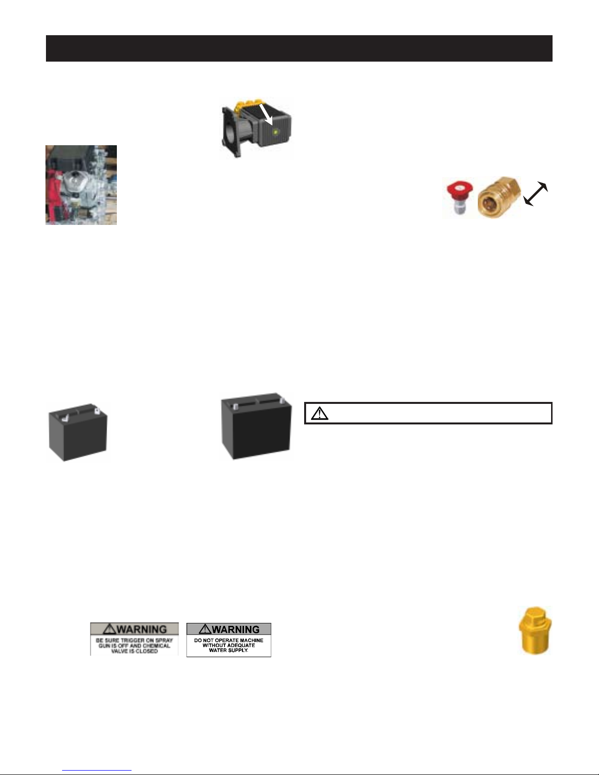
5. BATTERY INFORMATION
If you did not order a battery with your machine you
will have to buy one and fill it with electrolyte (available at local auto parts store).
!WEAR EYE PROTECTION!
If the opening on your battery box
measures 9" by 6" we
recommend Exides'
EB22F
recommend Exides' group 46-60 550 CCA battery. Deep
cycle batteries are recommended to extend battery life.
Always connect the positive battery cable before the
negative and coat the battery terminals with corrosion
inhibitor to prevent corrosion.
6. If wheel kit, accessories, or discharge hose are not
installed, see your local dealer for instructions & installation.
U1L/GTH 235CCA
battery. If the opening
measures 8" by 12" we
EB24F
OPERATION:
1. STARTING:
A. Electric Powered Units:
Connect power supply and ensure that all wiring connec-
tions and voltages are of sufficient rating to comply with
the equipment's requirements. Turn pump power switch
on. If unit is equipped with auto-start, keep all power
switches off when left unattended. (Unit will only turn on
when trigger gun is pulled.)
B . Gasoline Engine Units: To reduce the risk of starter
damage remove spray nozzle from wand and pull spray gun
trigger while cranking engine. After start, release trigger and
replace spray nozzle. Be sure nozzle is properly positioned
in quick disconnect before spraying:
2. PURGE AIR FROM SYSTEM:
Squeeze the trigger on the spray gun until a constant stream of
water comes out. (Purging works best with nozzle removed
from wand and/or dual wand in the low pressure mode.)
3. SELECT DESIRED
NOZZLE
Connect nozzle securely
to spray wand. If equipped,
close pressure adjusting
knob on dual wand. Hold gun firmly, squeeze trigger for
high pressure spray. O-ring should be replaced with 1/4"
or 3/8" EPDM.
CAUTION - Gun kicks back - hold with both hands.
WARNING - Risk of explosion - DO NOT spray
flammable liquids.
4. START BURNER: To create hot water on high pressure
washers equipped with heat exchangers, release the trigger
on the gun, turn the burner to the on position, and turn the
thermostat to the desired temperature.
Squeeze the trigger on the spray gun and the burner will
begin heating the water. It will stop firing whenever the
water spray is off or if the temperature setting is exceeded.
Warning: Cool down burner before shutting off.
5. STEAM: (If Equipped)
Insert steam nozzle and turn thermostat to 250º steam
setting. The steam nozzle is sized for approximately
25% less water volume than the hot water mode.
6. BYPASS MODE:
System will go into bypass mode when machine is left
running and trigger gun is closed. Bypass mode is when
the inlet water coming into the pump recirculates through
the unloader across the pump head. If left in bypass too
long - More Than Five Minutes - friction created by the
movement of the water will begin to heat the water at a
rapid rate. If equipped with a THERMAL DUMP
VALVE, water exceeding 145°F will cause the valve to
open allowing the hot water out of the system into the
atmosphere and allow cool water in. The valve
will reset itself when water temperature comes
down to a safe level.
If equipped with a bulk water tank, water can be
bypassed back through the tank allowing for a
larger volume of water to be recirculated through the pump
head thus reducing heat on the pump seals.
Lock collar after nozzleis inserted
!Warning: Do not leave in bypass for longer than five
minutes to prevent pump from overheating.

SHUT DOWN / SYSTEM INFORMATION 7
7. SET CHEMICAL INJECTION:
If unit is equipped with inlet chemical injection, place
chemical pickup tube in pre-mixed chemical solution and
open chemical valve for desired chemical concentration.
Rinse and close valve after use, do not use harsh chemicals through the inlet injector system. If unit is equipped
with a downstream chemical injector, connect the chemical
injection assembly into the high pressure discharge hose
quick connects. Place the chemical pickup into chemical
solution and turn brass collar to adjust concentration. The
chemical will inject only when you drop the outlet pressure
by opening the valve on the dual wand or changing to a low
pressure nozzle. Soap the surface from the bottom up.
Close chemical valve when not in use.
MAINTAIN PH BETWEEN 5 & 9
8. If equipped, AF2 (2) gun operation, select "50%"
nozzle from panel and insert into coupler on spray gun
for full pressure output when using two guns at the
same time. Flow can be reduced by selecting flow
reduction nozzles only when one operator is using the
machine. Maximum temperature is 200° F.
SHUT DOWN:
1. TURN BURNER SWITCH TO THE OFF POSITION.
2. RINSE & CLOSE CHEMICAL VALVE.
3. SQUEEZE THE TRIGGER ON THE SPRAY GUN
UNTIL THE WATER BECOMES COOL.
4. TURN MOTOR/ENGINE SWITCH OFF with the
appropriate controls.
5. TURN OFF WATER SUPPLY.
6. SQUEEZE TRIGGER TO RELEASE ANY
TRAPPED PRESSURE IN DISCHARGE HOSE.
7. ANTIFREEZE EQUIPMENT:
In the event that the equipment is not to be used for an
extended period, store in heated space or antifreeze the unit.
Run the machine until the float tank is near empty, fill with
a 50% mix of water and antifreeze and run until antifreeze
appears at the high pressure outlet. If unit is equipped with
a blow out valve, it may be blown out with compressed air
in addition to using antifreeze solution. On direct feed units
(no float tank), use a 5' garden hose to draw the antifreeze
mix from a bucket. Or blow out the unit with compressed
air until only air and no water comes out of the discharge.
CHASSIS & TRAILER ASSEMBLY:
To maintain teh appearance of hte machne, use stainless steel
claner on teh stainless panels.
Check tire pressure. Check all bolts including the lug nuts for
tightness and condition periodically. Grease wheel bearings as
required and adjust after first month.
TIRE PRESSURE
T200 T300 T400 T500
35psi 35psi 40psi 40psi
POWER SYSTEMS:
ELECTRIC MOTORS: All single phase
electric motors contain a manual or automatic thermal overload which will shut down
the motor if it overheats. If the overload or
starter shuts down the motor, have an electrician or an authorized Hydro Tek distributor
check for electrical problems. Voltage reading under load
should be +/- 10% of name plate voltage on motor. The
motor can be reset by depressing the red overload button
located on either the motor or the starter, (as shown above).
Use thumb pressure only - DO NOT force. Wait for motor
to cool before re-setting. The automatic overload will reset
itself after the motor has cooled.
Never spray water on the unit, or damage to the electric
motor(s) may occur.
HORSE
POWER
A=TOTAL SYSTEM AMPERES
115V
WIRE
208V
WIRE
208V
WIRE
230V
1PH
SIZE
1PH
SIZE
3PH
1.5 15A 12/3 N/A N/A N/A N/A 10A 14
2 20A 12/3 N/A N/A N/A N/A 12A 14
4 N/A N/A 21A 10/3 N/A N/A 20A 10/3
5 N/A N/A 24A 10/3 N/A N/A 23A 10/3
6.5 N/A N/A N/A N/A N/A N/A 27A 10/3
7.5 N/A N/A N/A N/A N/A N/A 35A #8
SIZE
1PH
WIRE
SIZE
Consult the factory if running an electric machine from a
generator. Three times total system wattage is required.
A fused disconnect switch of sufficient ampere rating
should be installed by an electrician to provide power to the
machine. Refer to the chart above for electrical requirements: (208 Volt is acceptable, but unit motor must be under
nameplate amps; turn psi down). If your unit is equipped with
a ground fault interrupter, it will have to be reset whenever it
is plugged in, or if a ground fault interruption occurs. Test
regularly for proper operation.
GASOLINE ENGINE: With the proper care and maintenance, your gasoline engine will give years of trouble free
service. Please follow the Service and Maintenance Guide
and the enclosed engine sheet or contact your local authorized
engine dealer for maintenance and repairs.
Use unleaded gasoline with an octane rating of 87 or
higher in the engine fuel tank. Consult engine manual for
proper oil type and capacity. Change oil every 50 hours and
the filter every 100 hours (see engine manual). Do not rely
on the low oil shutdown (if equipped) as a reminder to add
oil. Engine damage from lack of oil will typically not be
warranted even if the low oil system failed.
On machines with a 115V generator or a 12V burner, the
throttle is preset at the factory (See Generator section on this
page for adjustment).
POWER TRANSMISSION:
DIRECT DRIVE: Pump is bolted
directly to the motor/engine. If pump
needs to be removed, do not force off by
prying or damage may occur. When
reassembling, coat the entire motor shaft
with heavy grease, or a generous amount
8 SYSTEM INFORMATION
of anti-seize and use service removable "lock tight" on mounting
bolts.
BELT DRIVE: Check belt condition, alignment and
tension periodically. Replace belts when they show signs of
wear or cracking. Tighten belts by loosening the mounting bolts
on the pump and generator to permit them to slide. Turn the
horizontal rail adjusting bolts to tighten belts until they deflect ¼"
to ½" inch with finger pressure.
GENERATOR:
Some self-contained Hot Water Units are equipped with a
115 volt generator to power the diesel burner. The generator
output voltage must be between 110 to 130 Volts, (or between
59 to 63hz), when the unit is under full load. If the generator
voltage falls out of this range the RPM
of the engine will need to be adjusted to
proper speed. If the engine cannot
maintain the proper RPM do not use
the burner or any power from the
generator until the engine is repaired.
A switch/circuit breaker will need to be
reset if the circuit is overloaded.
To extend generator life make sure the
burner is off when the engine is started or
stopped. Keep generator dry. Do not spray off with trigger
gun.
If unit is equipped with auxiliary generator power outlets,
they are located on the back of the electrical box. Do not
plug in accessories over 1200 watts or 10 amps.
PUMPING SYSTEM:
PUMP: The pump is a positive displacement, oil bath
crankcase, triplex plunger type. It contains 3 plungers which
move forward and backward in a cylinder to propel water past
3 inlet valves and 3 discharge valves into a high pressure
manifold.
The crankcase oil window or dip stick should be checked
for oil level and clarity. Check the pump for oil or water
leaks before each use. The sight window is located at the rear
(opposite the head) of the pump and should be filled to the red dot
with AR recommended oil, or Cat Pump recommended
oil available at your Hydro Tek dealer. Wobble plate
pumps use synthetic oil which only needs to be changed
if the oil becomes contaminated. If the
oil becomes milky in color, moisture is
entering the crankcase. Change the oil
and contact your authorized Hydro
Tek dealer if the problem persists.
To increase pump life, prevent cavitation (air bubbles),
overheating, and dirty water. Cavitation can be prevented by
keeping filters clean and checking for air in pump
feed lines. Do not run the pump in the bypass
mode (pump running with the trigger gun off), for
a period of more than 5 minutes or the pump will
begin to overheat (maximum water temperature
is 145ºF). Do not run pump dry. Protect from freezing. Do
not run a frozen pump until it is completely thawed.
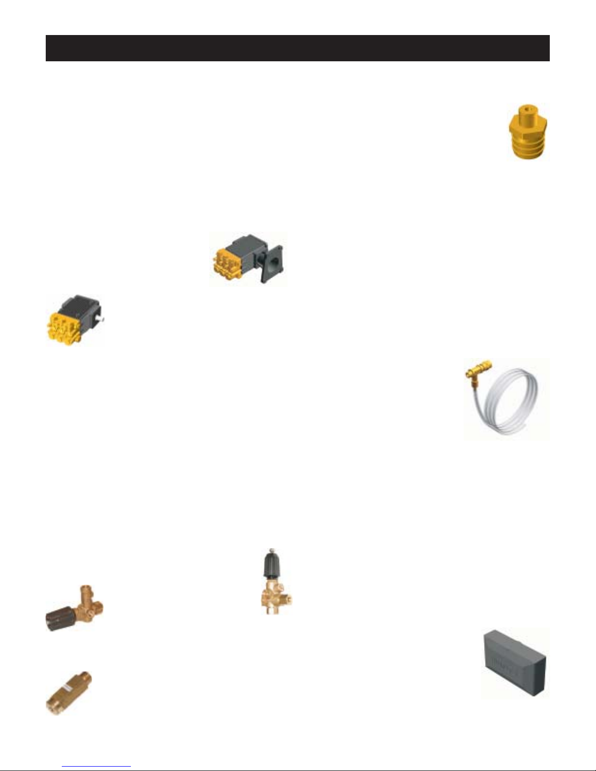
UNLOADER AND PRESSURE RELIEF VALVE: The
unloader valve is preset at the factory to govern the proper
output pressure of your machine. It will release
the pressure of the pump output back into the
inlet if the trigger on the spray gun is released.
NEVER increase the set pressure on the unloader to exceed the specifications for your
machine. The unloader should be adjusted only by qualified
personnel.
All hot water machines are equipped with a SAFETY
PRESSURE RELIEF VALVE. In the unlikely event that
your unloader fails, or if the burner overheats and builds
excessive pressure, the pressure relief valve will vent the
pressure into the atmosphere. If this occurs, turn off the
machine and have it checked by an authorized dealer. The
pressure relief valve will automatically reset itself.
BURST DISK TECHNOLOGY: This additional safety
feature functions to protect the coil and other components
from overpressurizing from the heating system and high
system spikes of pressure. If this component ruptures, you
should take the machine in to an authorized Hydro Tek
dealer. Do not plug off and continue to run.
An optional DOWNSTREAM
INJECTOR is available if harsh chemicals need to be applied. The downstream injector will apply chemicals only
at low pressure. If equipped standard
with downstream injection, adjust concentration level by turning brass collar on the injector, or the
knob on pump or control panel. Read and follow all safety
instructions on the detergent label.
WATER SUPPLY: An adequate water supply must be
maintained to the pump at all times. If the inlet flow is too low
or if there is air in the water supply, the pump will run rough,
pulsate and lose pressure. Maximum inlet water temperature
is 145ºF. If the pump is run dry, it can quickly overheat.
The water is filtered by a garden hose adapter screen.
Clean and replace as required or install a large capacity
strainer to insure a clean supply of water.
DIRECT WATER FEED: Maintain an inlet water pressure
between 25 PSI and 60 PSI using a ¾" I.D. hose. Install a back
flow preventer on your supply hose if State or Local ordinances
require it. Install a water regulator if your water pressure exceeds
60 PSI.
FLOAT TANK WATER FEED: A
float tank is used on some models to
regulate the incoming water supply to
the pump and introduce chemicals into
the inlet of the pump.
The float tank and filter should be flushed out if debris
accumulates in the bottom. If the float tank overflows or
 Loading...