

Page 1
Operation & Maintenance Manual
Discfilter HSF2600 series
PFC
Type: 2F, 3F
Serial no: ………………………………
Revised: 2015-08-26 EN
Page 2

2
LIST OF CONTENTS
. INTRODUCTION
. SAFETY INSTRUCTIONS
2.1 Warning symbols 5
2.2 CE marking 5
2.3 Conversion 5
2.4 Personnel requirements 5
2.5 Emergency stop 6
2.6 Electrical safety 6
2.7 Safety instructions 6
. HYDROTECH DISCFILTER HSF SERIES
3.1 Overview 7
3.2 Identifying the filter 9
. START UP AND OPERATION
4.1 Check procedures during start-up 10
4.2 Automatic settings 11
4.2.1 Level differences 13
4.2.2 Operating mode HAND –
Continuous rotation/backwash 13
4.2.3 Operating mode AUTO – Automatic level control 13
4.2.4 Adjusting the level sensor 14
4.2.5 Setting of level relay 14
4.3 Backwash system 14
. FUNCTION
5.1 Intended use 15
5.2 Non-intended use 15
5.3 Filtration and backwash process 15
. MAINTENANCE/SERVICE
6.1 Filter cover 16
6.1.1 Hinge 16
6.1.2 Operating the filter cover 17
6.2 Operating the backwash pipe 17
6.3 Backwash system 18
6.3.1 Servicing nozzles 18
6.4 Backwash pipe position 20
6.4.1 Checking backwash pipe position 20
6.4.2 Adjusting backwash pipe position 21
“Operation & Maintenance Manual”, “Discfilter HSF2600 series”
Page 3

6.5 Cleaning the wash water filter 22
6.6 Bearings 23
6.6.1 Lubrication of swivel 23
6.6.2 Lubricating drum bearings 23
6.6.3 Checking drum bearing wear 24
6.7 Filter panels 25
6.7.1 High pressure cleaning 25
6.7.2 Chemical cleaning of filter panels 26
6.7.3 Changing filter panels 27
6.8 Drive chain 29
6.8.1 Checking the drive chain 29
6.8.2 Adjusting drive chain tension 30
6.8.3 Replacing the drive chain 30
6.9 Driven unit 31
6.10 Inlet seal 31
6.10.1 Checking inlet seal. 31
6.10.2 Replacing the inlet gasket 31
3
. MAINTENANCE SCHEDULE
APPENDICES
A: Technical specifications
B: Spare parts list
C: Measurement drawings
D: Drive unit
E: Backwash pump (option)
F: Actuators
G: Level sensor (option)
H: Pressostat (option)
I: Wiring diagram for control cabinet (option)
J: Frequency converter (option)
K: Soft start (option)
L: Logic module (option)
“Operation & Maintenance Manual”, “Discfilter HSF2600 series”
Page 4

4
. INTRODUCTION
1.
This manual contains instructions for the operation of Hydrotech Discfilters in the HSF2600
series, types 2F and 3F (standing filter).
Pay attention to all warning symbols that appear in this manual. If this information is
ignored it may result in serious personal injury and/or damage to equipment.
The manual must always be available to personnel that work with the equipment.
It is important that:
⊲ The manual and other applicable documents must be kept for the entire duration of the
equipment’s lifespan. The manual and other relevant documents are included as part of
the equipment.
The following documents (manuals) are a part of the equipment:
▹ Reception & Installation Manual
▹ Operation & Maintenance Manual
⊲ The manuals must be read carefully by all relevant personnel.
“Operation & Maintenance Manual”, “Discfilter HSF2600 series”
Page 5
5
Figure 2.1
Figure 2.2
. SAFETY INSTRUCTIONS
2.
Hydrotech Discfilters in the HSF2600 series are designed for safe operation provided that they
are installed correctly and used in accordance with the enclosed instructions. The equipment
must be installed correctly and adapted in accordance with local regulations. The machine
equipment is intended for use by multiple operators. You must read the applicable chapters
in this manual prior to using the equipment or performing maintenance.
⊲ Pay attention to all warning symbols that appear in this manual.
If this information is ignored it may result in serious personal injury and/or damage to
equipment.
⊲ Assume all electrical equipment to be live.
⊲ Consider all hoses and pipes to be pressurised.
⊲ Before carrying out maintenance work, the main power switch (see Figure 2.3) must be
turned to the OFF (0) position and locked with a padlock.
⊲ Maintenance and service may only be performed by authorised personnel.
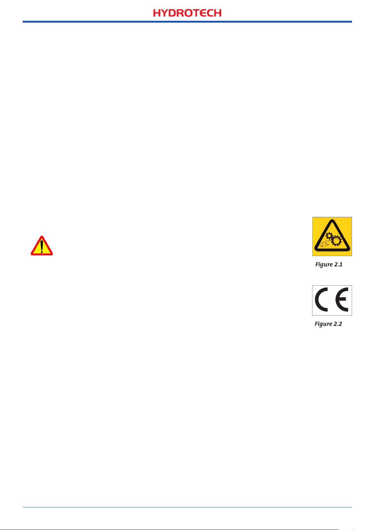
2.1 Warning symbols
Warning symbols are used in this manual to draw attention to potentially
dangerous situations:
Information that warns you of a potential risk of personal injury and/or
damage to equipment.
Warning labels (see Figure 2.1) are attached to the filter to warn personnel and
act as a reminder to keep hands and fingers away from the filter’s moving parts.
2.2 CE marking
This equipment is CE marked (see Figure 2.2), which guarantees that the
equipment is designed, manufactured and described in accordance with the
requirements set out in the EU Machinery Directive.
2.3 Conversion
The CE marking does not extend to any components that are not approved by Hydrotech AB
and that are used in conversion/reconstruction of the equipment.
The warning symbols and CE marking must be attached in such a way that they are fully visible. If
any part of the equipment with a warning symbol is replaced, a new symbol must be attached in
the same position. Damaged symbols and CE markings must be replaced immediately.
2.4 Personnel requirements
In order to avoid personal injury and damage to the equipment, service and maintenance
may only be carried out by personnel that have been trained to use the equipment and are
conversant in local regulations. Service and maintenance personnel may only handle those
parts of the equipment they have been trained for.
The operator may need to work inside the safety barrier and in the safety zone during maintenance and set-up before operation.
“Operation & Maintenance Manual”, “Discfilter HSF2600 series”
Page 6
6
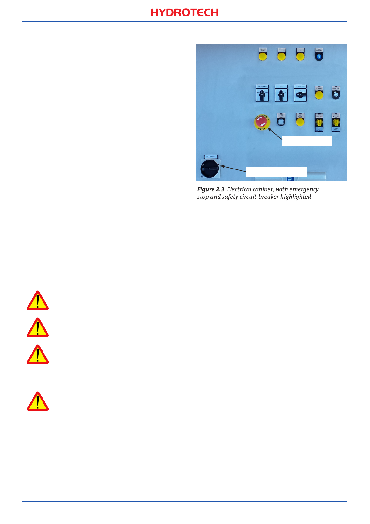
Figure 2.3 Electrical cabinet, with emergency
stop and safety circuit-breaker highlighted
2.5 Emergency stop
The filter is equipped with an emergency
stop and a main switch, see Figure 2.3.
In the event of a power outage, turn the
main power switch to the OFF (0) position to
prevent the filter drum from unintentionally starting when the power returns.
2.6 Electrical safety
Electrical installation must be carried out
Emergency stop
by a qualified electrician and in accordance
with local regulations. Also see Appendix I.
The filter tank must be connected to earth,
Main power switch
see section6.4 in the "Reception & Installation Manual".
The main power switch/emergency switch
must be fitted in accordance with applicable regulations.
2.7 Safety instructions
The filter is activated by turning the main power switch to the ON position (1), then selecting
AUTO or HAND mode using the mode selector located on the front of the electrical cabinet.
The filter stops if the mode selector is turned to the 0 (OFF) position.
NB See instructions in section 4.1.
Turn the main power switch to the OFF (0) position and lock it with a padlock before performing any work on the filter.
Access to the filter by unauthorised persons is strictly prohibited. Outdoor installations must
be fenced in.
The filter can start rotating without warning if automatic control is activated. Moving parts
must not be touched.
Safety guards are fitted around the power transmission. Make sure these are secured and
correctly fitted.
The aerosols from the backwash water may contain harmful substances.
Measured noise levels from the filter are less than 74 dB(A). Personnel should use appropriate
protection, when necessary, in accordance with local regulations.
“Operation & Maintenance Manual”, “Discfilter HSF2600 series”
Page 7

7
Figure 3.1 Hydrotech Discfilter in HSF2600 series type 1F (side view).
Figure 3.2 Hydrotech Discfilter in HSF2600 series type 2F (from inlet side).
. HYDROTECH DISCFILTER HSF SERIES
3.
3.1 Overview
A. Inlet side
A
C
B. Inlet
D
passage
C. Filter cover
B
D. Outlet
side
G H
C
J
I
E
F
E. Backwash pump
(option)
F. Backwash water filter
G. Actuator for
opening cover
H. Pressostat (protects
L
M
N
O
P
Q
R
P
T
U
V
pump from running
dry) (option)
I. Electrical connection
box
J. Shut-off valve,
backwash pipe
K. Manometer
L. Lubrication point
M. Bypass valve for
nozzle check
N. Connection, chemical
cleaning
O. Sludge trough
P. Holder for level sen-
sor, inlet water
Q. Holder for level sen-
sor, outlet water
R. Sludge outlet
S. Filter panel
T. Filter segment
U. Drum
V. Drum bearing,
inlet side
“Operation & Maintenance Manual”, “Discfilter HSF2600 series”
Page 8
8
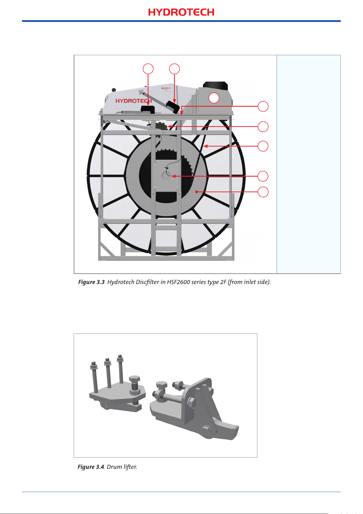
Figure 3.3 Hydrotech Discfilter in HSF2600 series type 2F (from inlet side).
Figure 3.4 Drum lifter.
BA
A. Actuator for
C
D
backwash
system
servicing
E
F
G
H
B. Actuator for
opening cover
C. Drive unit
D. Lubrication
point
E. Backwash pipe
drive
F. Drive chain
G. Drum bearing,
outlet side
H. Drum
Two drum lifters are supplied unassembled for each installation, see Figure 3.4. These are only
used when servicing drum bearings. The supplier should be contacted when servicing bearings.
“Operation & Maintenance Manual”, “Discfilter HSF2600 series”
Page 9
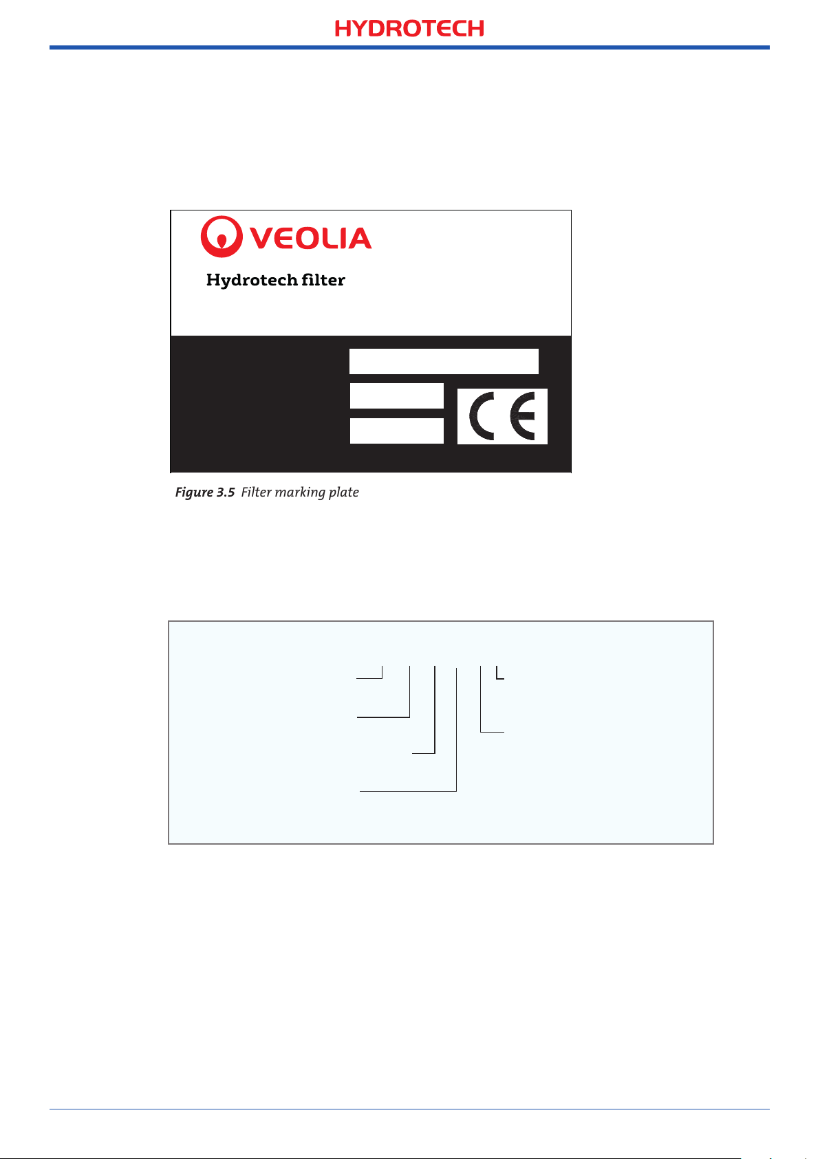
3.2 Identifying the filter
Figure 3.5 Filter marking plate
The filter type, serial number and year of manufacture are stated on the identification plate.
The filter type and serial number are also stated on the front of this manual.
Mejselgatan 6, 235 32 Vellinge, Sweden
Website: www.hydrotech.se E-mail: mailbox@hydrotech.se
9
xxxxFilter type:x
xxxxSerial No.x xx
xxxxYear:xxxxx xx
Definition of filter designation:
Filter type
HSF = Hydrotech Disc Filter
Disc diameter:
26 = 2.6 m
Max. no. of discs
12 = Drum can hold 12 discs
No. of installed discs
8 = 8 discs are installed
HSF2612/8-2F
9568
2011
HSF 26 12/8 - 2 F
Model
F = Industrial model
Disc filter type
1 = Filter with tank
2 = Filter without tank
“Operation & Maintenance Manual”, “Discfilter HSF2600 series”
Page 10
10
4.
. START UP AND OPERATION
4.1 Check procedures during start-up
1. Check that the drive unit cover is installed correctly.
2. Set the pump switch to the 0 (OFF) position, see Figure 4.1.
3. Set the main power switch to the 1 (ON) position.
4. Set the mode selector to HAND mode.
5. Open the water supply partially so that water slowly flows into the filter drum. Make sure
that the difference in water level between the inside and outside of the filter drum does
not exceed 450 mm (see section 4.2.1). If the filter cover becomes clogged, it may be necessary to fill the filter tank with water from an external source or to remove a filter panel
and allow unfiltered water to fill the filter tank.
A difference in water level between the inside and outside of the filter drum greater than
450mm will damage the filter.
6. When the water level inside the filter tank is above the pump suction pipe (or the pump if
a CRK or MTR pump is installed), the pump must be started by turning the pump switch
to the 1 (ON) position.
NOTE Also read section 2.7 (Safety instructions).
The backwash pump must not be started until the water level has reached the suction pipe
(or pump if a CRK or MTR pump is installed), otherwise the pump will run dry and fail.
7. If the water level inside the filter tank reaches the overflow wall, set the mode selector to
the AUTO position (see section 4.2).
8. Fully open the water supply.
The filter is now run in the mode for automatic level control. It may be necessary to adjust the
level sensor so that the filter can be run optimally.
“Operation & Maintenance Manual”, “Discfilter HSF2600 series”
Page 11
4.2 Automatic settings
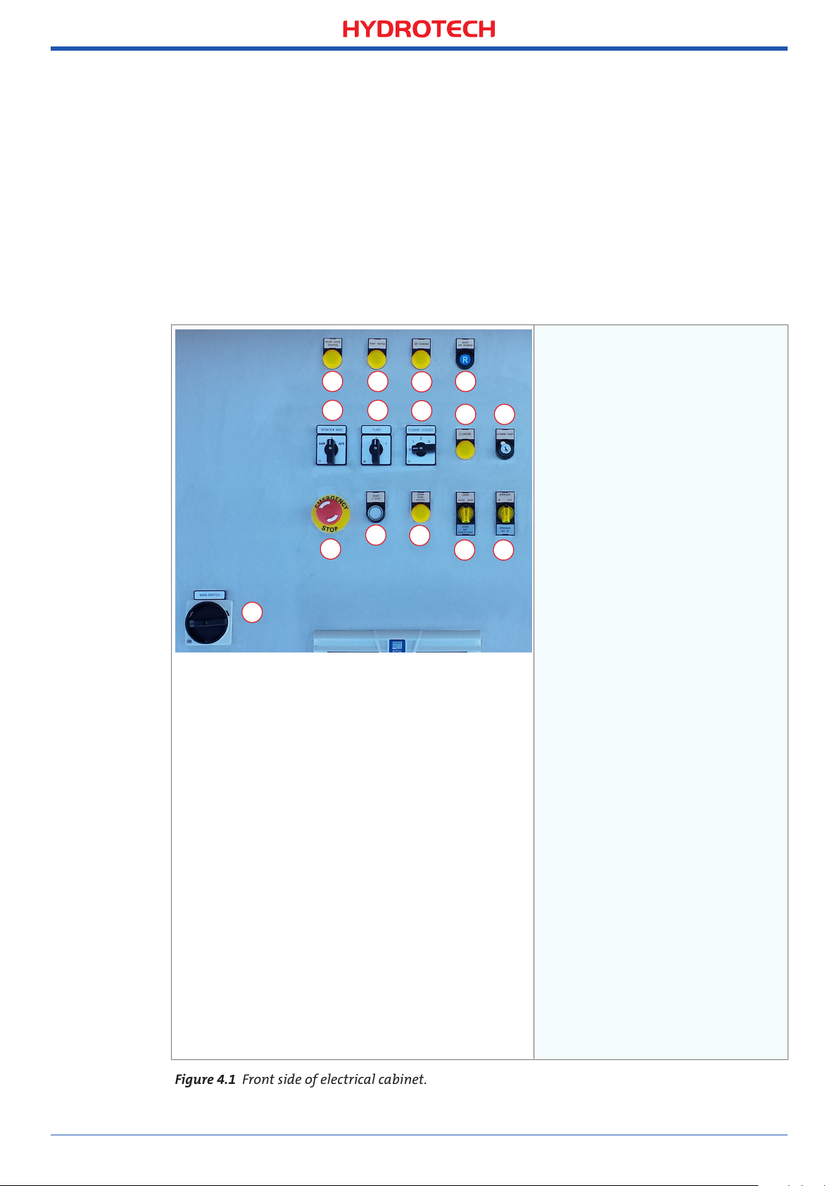
Figure 4.1 Front side of electrical cabinet.
The control system for the HSF2600 series must always be equipped with a frequency converter for the drive unit. This is factory calibrated if delivered from Hydrotech. To perform a
soft start of the drive motor, the frequency converter settings must be min. 5 sec “ramp up”
and min. 3 sec "ramp down". The filter works with 50 Hz as standard.
If the filter is equipped with Hydrotech’s control system, the filter has two operation modes:
1. Continuous rotation (HAND mode)
2. Automatic level control (AUTO mode).
Turn the mode selector to select the operating mode.
A. DRUM DRIVE TRIPPED. Lamp that
indicates when the frequency
A B
E F
K
J
O
C
G
L
D
H I
M N
converter has tripped.
B. PUMP TRIPPED. Lamp that
indicates when the backwash
water pump’s motor protection
device has tripped.
C. DRY RUNNING. Lamp that
indicates when the dry running
protection device for the backwash water pump has tripped.
D. RESET DRY RUNNING. Resetting
the backwash water pump’s dry
running protection.
E. OPERATION MODE. Mode
selector
F. PUMP. Pump switch.
G. CLEANING SEQUENCE.
Selector for number of
sequences, chemical cleaning.
H. CLEANING. Lamp that indicates
when the chemical wash is in
progress.
I. CLEANING START. Chemical wash
switch, key operated.
J. EMERGENCY STOP. Emergency
stop.
K. RESET E-STOP. Resetting the
emergency stop.
L. COVER OPEN SERVICE. Lamp that
indicates when the cover is open
so that the backwash ramp can
be extended.
M. COVER NOT OPEN/CLOSED.
Switch for operating the cover.
Lamp that indicates when the
cover is not fully opened nor
fully closed.
N. SPRAYBAR NOT IN. Switch for
operating the backwash ramp.
Lamp that indicates when the
backwash pipe is not retracted.
O. MAIN SWITCH. Main power
switch.
11
“Operation & Maintenance Manual”, “Discfilter HSF2600 series”
Page 12

12
Figure 4.2 Component parts of the Hydrotech electrical cabinet.
A
B
C
D
A. Contactor
B. Fuses
C. Fuses
E
F
G
D. Mains supply
E. Contactor
F. Relays
G. Emergency stop
relay
H
I
J
K
L
H. Main power switch
I. Frequency converter
J. Soft start pump
M
K. Logic module
L. Level relays
M. Terminal blocks
“Operation & Maintenance Manual”, “Discfilter HSF2600 series”
Page 13

4.2.1 Level differences
The maximum permitted difference
between the water levels inside and
outside the drum is 250 mm during
normal operation (see Figure 4.3).
The recommended level difference
is 100-200 mm.
If an even flow after the filter is
required, the filter must be run
with a small level difference.
The filter must be installed so that the
level difference in the event of operating disturbances under no circumstances exceeds 450 mm.
The filter shall be operated so that the
level difference during normal operation does not exceed 250mm.
13
Max. 250 mm
Figure 4.3 Maximum permitted level difference during
level-controlled operation.
Prolonged operation with a greater level difference will significantly shorten the life of the
filter panels and other vital parts.
4.2.2 Operating mode HAND – Continuous rotation/backwash
Operation with continuous drum rotation and backwash. In this mode, the water level inside
the drum is kept virtually constant.
The level sensor and the automatic level control are disabled when the HAND operating mode
is selected.
4.2.3 Operating mode AUTO – Automatic level control
With automatic level control enabled, drum rotation and the backwash pump are activated
when the water level inside the drum reaches the level sensor. If an external wash water
supply is used, the level sensor can control a solenoid valve instead of a pump.
The water level inside the drum will vary when AUTO mode has been selected. The water level
is at its lowest immediately after a backwash cycle and then rises until it reaches the level
sensor.
Opening the cover in AUTO mode deactivates drum rotation and backwashing.
“Operation & Maintenance Manual”, “Discfilter HSF2600 series”
Page 14

14
4.2.4 Adjusting the level sensor
NB Prior to servicing, read section 2.7.
Place the level sensor 50–100 mm below the overflow
wall. Optimal placement depends on the turbulence of
the water surface.
4.2.5 Setting of level relay
NB Prior to servicing, read section 2.7.
The sensitivity of the level sensor can be set from MIN
to MAX on the level relay’s upper adjusting screw.
The lower adjusting screw must always point to the side marked EMPTY, on this side there are
three different sensitivity ranges, H, S and L. If appropriate sensitivity cannot be set using the
selected sensitivity range, another sensitivity range can be chosen.
Figure 4.4 Adjusting the level sensor
4.3 Backwash system
NB Prior to servicing, read section 2.7.
The system pressure for backwashing must be set to 7-9 bar.
Newly connected pipe systems for external wash water should be flushed before they are
connected to the filter. Thoroughly check that the nozzles are not blocked, see section 6.3.
“Operation & Maintenance Manual”, “Discfilter HSF2600 series”
Page 15

15
Figure 5.1 Disc filter function.
5.
. FUNCTION
5.1 Intended use
The filter is designed and manufactured to remove solid particles in unpressurised water
flow systems. The filter is not a pressure vessel.
5.2 Non-intended use
Unless approved in writing by Hydrotech, the filter must not be used to filter liquids other
than water. The filter must not be installed in an environment with an explosive atmosphere
or another risk of explosion, such as high concentrations of dust.
5.3 Filtration and backwash process
A brief description of the process is given below.
1. The water to be filtered flows with gravity from the inside of the filter drum out to the
filter segments.
2. Solid particles are separated from the water using a filter medium attached to both sides
of the filter segments, whilst clean water passes through the filter medium to the outside
of the filter segment.
Filter
panels/
media
Backwash
nozzles
Sludge
trough
Sludge/
reject water
Outlet
Inlet
Bypass
3. Operating mode AUTO – The solid particles that accumulate on the inside of the filter
medium gradually reduce the water flow through the filter panel. The water level on the
inside of the drum begins to rise. When the water reaches the level sensor, drum rotation
and backwashing is started. Operating mode REMOTE – The filter is controlled as in AUTO
operating mode or with an external control (e.g. time-controlled drum rotation and backwashing). Service HAND – Drum rotation and backwashing are started manually.
4. The backwash nozzles spray wash water on the outside of the filter panels. The solid
particles that accumulate are washed from the filter panels to the sludge channel, at the
same time as the drum rotates.
5. The removed particles and backwash water flow with gravity out of the filter.
“Operation & Maintenance Manual”, “Discfilter HSF2600 series”
Page 16

16
Figure 6.1 a Locked hinge
b Open hinge
Figure 6.2 Shows the location of the lockable hinges and the drive unit.
6.
. MAINTENANCE/SERVICE
This chapter describes how maintenance and servicing is to be carried out. Chapter 7
describes how often the various components require servicing.
6.1 Filter cover
NB Prior to servicing, read section 2.7.
The filter cover for the Hydrotech Discfilter HSF2600 series is controlled from the electrical cabinet
and can be opened in two directions depending on which side of the filter needs to be accessed.
6.1.1 Hinge
Before the filter cover is operated from the operator panel, its hinge must be locked on the correct side. The locking pin (A) must lock the hinge lock (B) securely as shown in Figure 6.1a below.
Make sure that the filter cover is completely closed and that the hinge lock (B) shown in
Figure 6.1a surrounds the shaft (C) in Figure 6.1b.
The locking pin (A) and the hinge lock (B) must ALWAYS sit on the two outermost hinges (E),
as shown in Figure 6.2 or on the opposite side depending on which direction you want the
cover to open in.
A
B D C
In order to access the backwash pipe, the hinges must be locked (E in Figure 6.2) on the side
of the cover on which the drive unit (F) sits (see Figure 6.2), and the hinges must be open
(see Figure 6.1b) on the opposite side, i.e. the backwash pipe side.
F
E
“Operation & Maintenance Manual”, “Discfilter HSF2600 series”
Page 17

6.1.2 Operating the filter cover
Figure 6.3 Switch for operating
the cover and backwash pipe
Figure 6.4 Filter cover open and backwash pipe extended.
1. The filter cover is opened by turning the cover switch to the
OPEN position, see Figure 6.3.
2. When the cover is opened in AUTO operating mode, drum
rotation and backwashing are activated. In the HAND operating mode the drum rotates.
3. The filter cover is closed by turning the cover switch to the
CLOSE position.
NB The indicator lamp "COVER NOT OPEN/CLOSED" will illuminate when the cover is not fully opened nor fully closed.
Check that the hinges are fully locked before opening the filter cover, see section 6.1.1 "Hinges".
6.2 Operating the backwash pipe
NB Prior to servicing, read section 2.7.
17
1. First open the cover fully
on the backwash pipe
side, see section 6.1 2,
the "COVER OPEN SERVICE" lamp will light up
when the cover is fully
open.
2. Extend the backwash
pipe by turning the
backwash pipe switch
to the OUT position, see
Figure 6.3.
3. The backwash pipe is
retracted by turning the
backwash pipe switch to
the IN position.
4. Close the cover, see section 6.1 2.
NB The indicator lamp "SPRAYBAR NOT IN" must be off to be able to operate the cover.
“Operation & Maintenance Manual”, “Discfilter HSF2600 series”
Page 18

18
Figure 6.5 Main valve A and bypass valve B.
6.3 Backwash system
NB Prior to servicing, read section 2.7.
The most common cause of disruption in the backwash system is nozzle clogging. Clogging is
caused by particles in the wash water and/or by e.g. biological fouling in the pipe system.
6.3.1 Servicing nozzles
1. Turn the mode selector to AUTO position.
2. Turn the pump switch to 0 (OFF).
3. Open the cover on the the backwash pipe side and extend the backwash pipe as described
in sections 6.1 and 6.2.
4. Open the bypass valve (B) and close the main valve (A), see Figure 6.5.
Maintain a safe distance from the filter whilst the drum is rotating.
5. Start drum rotation by turning the mode selector to the HAND position.
6. Start the pump by turning the pump switch to 1 (ON).
A B
“Operation & Maintenance Manual”, “Discfilter HSF2600 series”
Page 19

7. Adjust the backwash water flow using the bypass valve so that there is a small but constant
Figure 6.6 Hydrotech backwash nozzles.
flow through the nozzles. This makes it easy to identify which nozzles need to be cleaned.
8. Check for clogged nozzles by comparing the water jets.
The operating time in this mode must be minimised in order to not risk the pump overheating.
9. Fully or partially clogged nozzles must be cleaned.
A. Nozzle nut with
A
spray nozzle
B. Rubber seal
B
C. Nozzle
C
attachment
19
E
D
D. O-ring
E. Screw
10. Remove the nozzle nut by turning it a ¼ turn anticlockwise. Do not lose the rubber seal!
11. Clean the nozzle using compressed air or a plastic brush. Never use a steel brush or metal
pins as these may damage the nozzle.
12. Fit the nozzle in reverse order. Check that the nut has reached the stop position once it
has been tightened a ¼ turn clockwise.
13. Turn the mode selector to the AUTO position.
14. Open the backwash water main valve and close the bypass valve.
15. Reset the backwash pipe to operating mode.
16. Close the filter cover
17. Start operation again as described in section 4.1.
“Operation & Maintenance Manual”, “Discfilter HSF2600 series”
Page 20

20
Figure 6.7 Lowest position of backwash pipe during operation.
6.4 Backwash pipe position
NB Prior to servicing, read section 2.7.
6.4.1 Checking backwash pipe position
1. Turn the pump switch to the 0 position.
2. Open the cover.
3. Start drum rotation by turning the mode selector to HAND.
Maintain a safe distance from the filter whilst the drum is rotating.
4. When the drum rotates, the backwash pipe moves slowly. Stop drum rotation when the
backwash pipe is in its lowest position.
L
min
5. Check that the distance L min is not less than 55 mm, see Figure 6.7.
If the distance L min is less than 55 mm, the equipment may suffer serious damage.
6. If necessary, adjust the backwash pipe safety stop in accordance with section 6.4.2.
7. Adjust the backwash pipe safety stop in accordance with section 6.4.2.
8. Close the filter cover.
9. Start operation again as described in section 4.1.
“Operation & Maintenance Manual”, “Discfilter HSF2600 series”
Page 21

6.4.2 Adjusting backwash pipe position
Figure 6.8 Screw and nut for adjustment of rinse header position and rinse header safety stop
1. Turn the main power switch to the OFF (0) position and lock with a padlock.
2. Undo the nut (B), see Figure 6.8.
3. Adjust the position of the backwash pipe using the screw (A).
A
B
21
4. Secure the screw (A) using the nut (B).
5. Check backwash pipe position as described in section 6.4.1.
6. Adjust the rinse header safety stop in the corresponding way using the screw (C) and
nut(D). The screw must be set so that the distance L in Figure 6.7 cannot, under any
circumstances, be less than 55 mm.
7. Close the filter cover
C
D
8. Start operation again as described in section 4.1.
“Operation & Maintenance Manual”, “Discfilter HSF2600 series”
Page 22

22
Figure 6.9 Hydrotech wash water filter.
6.5 Cleaning the wash water filter
NB Prior to servicing, read section 2.7.
If the pressure gauge indicates a pressure that is more than 0.5 bar below normal pressure,
it’s time to clean the wash water filter.
1. Turn the main power switch to the OFF (0) position and lock with a padlock.
2. Drain the wash water filter by opening the valve (A), see Figure 6.9.
3. Loosen the wing nut (B) and remove the clamp ring.
4. Lift off the backwash water filter cover (C).
5. Pull up and clean the filter insert.
6. Place the filter insert in the cover.
7. Refit the cover/filter insert and the clamping ring.
8. Close the drain valve (A).
9. Start operation in accordance with section 4.1.
C
B
A. Drainage
B. Wing nuts
C. Cover
“Operation & Maintenance Manual”, “Discfilter HSF2600 series”
A
Page 23

6.6 Bearings
Figure 6.10 Swivel.
Figure 6.11
NB Prior to servicing, read section 2.7.
6.6.1 Lubrication of swivel
The swivel, the backwash pipe bearing, is located under the cover and connects the piping
with the backwash pipe, see Figure 6.10.
When lubricating the swivel, the instructions below must be followed:
1. Turn the mode selector to "HAND" and lift the filter cover on the backwash pipe side, see
section 6.1.
2. Turn the main power switch to the OFF (0) position and lock with a padlock.
3. Lubricate the swivel using the recommended grease (see chapter 7).
23
4. Close the filter cover.
5. Start operation in accordance with section 4.1.
6.6.2 Lubricating drum bearings
The bearings’ lubrication nipples are fitted on the outside of
the filter. Decals indicating the lubrication points are attached
to the filter, see Figure 6.11. The lubrication points are also
marked in Figure 3.2 and 3.3.
The drum must be rotating when the bearings are lubricated.
Lubricate the bearings using the recommended grease
(see chapter 7).
“Operation & Maintenance Manual”, “Discfilter HSF2600 series”
Page 24

24
Figure 6.12 Drum bearing on inlet side.
6.6.3 Checking drum bearing wear
1. Turn the main power switch to the OFF (0) position and lock with a padlock.
2. Drain the filter basin.
3. Check the drum bearings for wear. If the distance between the bearing housing (A) and
the shaft (B) is less than 29 mm (see Figure 6.12), the drum bearing must be replaced.
4. Contact your supplier if the drum bearing needs to be replaced.
5. Start operations again as set out in section 4.1.
A. Bearing
housing
B. Shaft
29-34 mm
A
B
“Operation & Maintenance Manual”, “Discfilter HSF2600 series”
Page 25

6.7 Filter panels
NB Prior to servicing, read section 2.7.
6.7.1 High pressure cleaning
It may be necessary to manually clean the filter panels. It may be obvious that manual cleaning is required as automatic backwashing starts on a more frequent basis. Manual cleaning
can be done using a high pressure washer.
When using a high pressure washer a wash pressure of max. 80 bar may be used. Never hold
the cleaning nozzle directly against the filter media.
An automatic high pressure washer, controlled from the operator panel, is available as an
optional extra. Contact your Hydrotech reseller.
25
“Operation & Maintenance Manual”, “Discfilter HSF2600 series”
Page 26

26
Figure 6.13 A floor plate must be lifted to access the connection to the chemical ramp.
6.7.2 Chemical cleaning of filter panels
Long-term clogging of the filter media can be caused by, among other things, iron, calcium
or organic fouling. This clogging can normally be removed through chemical cleaning. Three
proven products that do not affect the life of the filter media are dilute hydrochloric acid
(HCl), dilute sodium hypochlorite (NaClO) and dilute sodium hydroxide (NaOH).
The use of other types of cleaning agents may cause damage to equipment.
The cleaning products must not be mixed. If HCl and NaClO mix, toxic chlorine gas forms.
HCl and NaOH are highly corrosive. For safety advice, see applicable local regulations.
For more detailed instructions, please contact your supplier.
Hydrotech Discfilter HSF2600 is equipped with a chemical ramp to enable cleaning of longterm clogging of the filter panels.
The dosing equipment (option) must be connected to the chemical ramp connector, see
Figure 6.13. The control system is prepared and programmed for connection of a dosage
system. After completing electrical and mechanical installation, chemical cleaning is started
as follows:
1. Set the mode selector to AUTO and the pump switch to 1 (ON).
2. Set the number of cleaning sequences with the CLEANING SEQUENCE selector.
3. Start chemical cleaning with the CLEANING START switch.
“Operation & Maintenance Manual”, “Discfilter HSF2600 series”
Page 27

Once cleaning is completed the filter automatically returns to
Figure 6.15 Correct way of
changing filter panels.
normal operation in AUTO mode.
If necessary clean the chemical ramp nozzles as described below:
1. Remove the nozzle by turning it ¼ turn anticlockwise.
2. Clean the nozzle with compressed air or a plastic brush.
Never use a wire brush, metal pins or similar as these
can damage the nozzle.
3. Refit the nozzle.
6.7.3 Changing filter panels
It is important to maintain the balance of the drum when changing filter panels. Remove/refit every other filter panel. This prevents
un intentional rotation of the drum and reduces the load on the drive
chain and gearbox.
27
Figure 6.14 Nozzles on
chemical ramp.
NEVER remove or re-fit all filter panels on just ONE side of the disc,
see Figure 6.15.
1. Open the filter cover.
2. Turn the main power switch to the OFF (0) position and
lock it with a padlock.
3. Undo the filter segment cover screw and remove the cover,
see Figure 6.16.
4. Pull out the filter panel.
5. Insert a new filter panel and press in until it touches
the bottom.
The filter panels with steel frames MUST be installed with the filter
medium inwards and the frame outwards as shown in Figure 6.17.
6. Re-fit the filter segment cover (see Figure 6.16) and tighten the screw.
Maximum tightening torque: 3 Nm.
7. Close the filter cover.
8. Start operation again as described in section 4.1.
“Operation & Maintenance Manual”, “Discfilter HSF2600 series”
Page 28

28
Figure 6.16 Installation of filter segment cover.
Figure 6.17 Location of filter panels.
Max. tightening
torque 3 Nm
Frame
Filter panel
gaskets
Filter media
“Operation & Maintenance Manual”, “Discfilter HSF2600 series”
Page 29

6.8 Drive chain
Figure 6.18 Filter drive unit.
NB Prior to servicing, read section 2.7.
The filter is equipped with a chain drive. For technical data, see Appendices A and D.
6.8.1 Checking the drive chain
1. Turn the mode selector to the OFF (0) position and lift the filter cover on the same side as
the drive unit, see section 6.1.
2. Turn the main power switch to the OFF (0) position and lock it with a padlock.
3. Turn the drum by hand in the direction of rotation in order to stretch the chain.
4. Check the tension of the chain return; it must be possible to move it between 50-75 mm,
see figure.
29
5. If necessary, adjust the chain in accordance with section 6.8.2.
6. Close the filter cover.
7. Start operation again as described in section 4.1.
50-75 mm
“Operation & Maintenance Manual”, “Discfilter HSF2600 series”
Page 30

30
Figure 6.19 Engine suspension plate.
6.8.2 Adjusting drive chain tension
Adjust drive chain tension as follows:
1. Turn the main power
switch to the OFF (0)
position and lock with
a padlock.
2. Loosen the four nuts (A).
See Figure 6.19.
3. Loosen the nut (B).
4. Adjust the tension of the
chain using the screw (C).
5. Secure the screw (C) using
the nut (B).
6. Tighten the four nuts (A).
C
B
A
7. Close the filter cover
8. Start operation again as
described in section 4.1.
When the drive chain cannot
be adjusted any longer, the
chain is worn and must be
replaced, see section 6.8.3.
6.8.3 Replacing the drive chain
1. Turn the main power switch to the OFF (0) position and lock with a padlock.
2. Lower the drive unit to its lowest position, see section 6.8.2.
3. Split and remove the drive chain. The drive chain can be separated in all links.
4. Fit the new drive chain.
5. Adjust drive chain tension in accordance with section 6.8.2.
6. Start operation again as in section 4.1 (Check measures for restart).
“Operation & Maintenance Manual”, “Discfilter HSF2600 series”
Page 31

6.9 Driven unit
Figure 6.20 Check of inlet seal.
NB Prior to servicing, read section 2.7.
For information about the drive unit, see Appendix D.
6.10 Inlet seal
NB Prior to servicing, read section 2.7.
6.10.1 Checking inlet seal.
1. Turn the main power switch to the
OFF (0) position and lock with a
padlock.
2. Reduce the water level in the filter
until the whole inlet gasket is
accessible.
31
3. Check the inlet seal for damage and
wear, see Figure 6.20.
4. If necessary, replace the inlet seal in
accordance with section 6.10.2.
5. Start operation again as described
in section4.1.
6.10.2 Replacing the inlet gasket
1. Turn the main power switch to
the OFF (0) position and lock with a
padlock.
2. Reduce the water level in the filter until the whole inlet gasket is accessible.
3. Note how the inlet gasket is fitted before it is dismantled.
4. Loosen the screws and nuts holding the inlet gasket in position.
5. Remove the inlet seal.
6. Fit a new inlet seal.
7. Start operations again as set out in section 4.1.
“Operation & Maintenance Manual”, “Discfilter HSF2600 series”
Page 32

32
7.
. MAINTENANCE SCHEDULE
Check/Action Maintenance interval
Check whether the wash water filter is
clogged. See section 6.5.
Check the filter panels for clogging and damage, see section 6.7.
Inspect the inside of the filter: Make sure no
large objects that can get caught in the drum,
filter segments or sludge trough have entered
the filter. Also check that the reject does not
accumulate (sediment) in the sludge trough.
NB Prior to servicing, read section 2.7.
Remove large objects and rinse the sludge
trough.
WARNING! Turn the main power switch to
the OFF position and lock with a padlock.
Rinse the metal surfaces of the filter structure with clean water. Clean (uncontaminated) metal surfaces minimise corrosion,
particularly in salt water applications.
Check the nozzles with respect to clogging.
See section 6.3.
The interval is based on experience from
the application in question. (When the
wash water pressure drops 0.5 bar below
the normal value.)
Once a week, or at another interval
based on experience from the
application in question.
Once a week or another interval based
on experience from the application in
question.
Twice a month or another interval based
on experience from the application in
question.
Twice a month or another interval based
on experience from the application in
question.
Lubricate the swivel to the backwash pipe
using grease of the type NLGI:2 (e.g. Molykote
Multilub, Rembrandt EP or equivalent
Twice a month with continuous drum
rotation. Once a month with intermittent drum operation.
grease). See section 6.6.1.
Lubricate the drum bearings (on the inlet and
drive side) using grease of the type NLGI:2
(e.g. Molykote Multilub, Rembrandt EP or
Twice a month with continuous drum
rotation. Once a month with intermittent drum operation.
equivalent grease). See section 6.6.2.
Check drive chain tension and condition.
See section 6.8
Four times a year with continuous drum
rotation. Twice a year with intermittent
drum rotation.
Check backwash pipe position,
Twice a year.
see section 6.4.
Check drive unit oil level, see section 6.9. Twice a year.
Check drum bearing wear, see section 6.6.3. Once a year.
Check inlet seal, see section 6.10. Once a year.
Change the gearbox oil. Oil type and volume
See Appendix D.
is stated on the motor label. Also see
Appendix D.
“Operation & Maintenance Manual”, “Discfilter HSF2600 series”
Page 33

33
“Operation & Maintenance Manual”, “Discfilter HSF2600 series”
Page 34

User guide in original
Hydrotech AB, A Veolia Solutions &
Technologies Company
Mejselgatan 6
SE-235 32 Vellinge
Sweden
Copyright © All rights reserved
Phone: +46 (0)40 - 42 95 30
Fax: +46 (0)40 - 42 95 31
E-mail: mailbox@hydrotech.se
Website: www.hydrotech.se
 Loading...