

Page 1

Discfilter HSF 26 - 1F series PFLC
Operation and maintenance manual
Revised:2018-05-23
Page 2

Operation & maintenance manual, Discfilter HSF2600 - 1F series with PFLC
LIST OF CONTENTS
1. INTRODUCTION 5
2. SAFETY INSTRUCTIONS 6
2.1 Warning symbols 6
2.2 CE marking 6
2.3 Conversion 6
2.4 Demands on personnel 7
2.5 Emergency stop 7
2.6 Electrical safety 7
2.7 Safety instructions 7
3. HYDROTECH DISCFILTER HSF2600-1F 9
3.1 Reception 9
3.2 Storage 9
3.3 Overview 10
3.4 Identifying the filter 13
4. GENERAL INSTALLATION INSTRUCTIONS 14
4.1 Liing the equipment 14
4.2 Installation site 15
4.2.1 Outdoor installation 15
4.2.2 Foundations 15
4.3 Electrical connection 15
4.4 Equipotential bonding 15
4.5 Checking the drum rotation and backwash pipe 16
4.6 Pipe connections 16
2
Page 3

Operation & maintenance manual, Discfilter HSF2600 - 1F series with PFLC
5. START UP AND OPERATION 17
5.1 Check procedures during start-up 17
5.2 Automatic seings 18
5.2.1 Level dierences 19
5.2.2 Operating mode AUTO – Automatic level control 19
5.2.3 Operating mode REMOTE – Remote control 19
5.2.4 Service mode HAND 19
5.3 Backwash system 20
6. FUNCTION 21
6.1 Intended use 21
6.2 Non-approved use 21
6.3 Filtration and backwash process 21
7. MAINTENANCE/SERVICE 23
7.1 Filter cover 23
7.1.1 Hinge 23
7.1.2 Operating the filter cover 24
7.2 Extend the backwash pipe 25
7.3 Backwash system 25
7.3.1 Servicing nozzles 25
7.4 Backwash pipe position 28
7.4.1 Checking backwash pipe position 28
7.4.2 Checking backwash pipe position 29
7.5 Cleaning the backwash water filter 30
7.6 Bearings 31
7.6.1 Lubrication of swivel 31
3
Page 4

Operation & maintenance manual, Discfilter HSF2600 - 1F series with PFLC
7.6.2 Lubricating drum bearings 31
7.6.3 Checking drum bearing wear 32
7.7 Filter panels 33
7.7.1 High pressure cleaning 33
7.7.2 Chemical cleaning of filter panels 34
7.7.3 Changing filter panels 36
7.8 Drive chain 38
7.8.1 Checking the drive chain 38
7.8.2 Adjusting drive chain tension 39
7.8.3 Replacing the drive chain 39
7.9 Drive unit 40
7.10 Inlet seal 40
7.10.1 Checking inlet seal 40
7.10.2 Replacing the inlet seal 40
8. MAINTENANCE SCHEDULE 41
Symbols used on Hydrotech filters 42
Manuals & technical information 43
4
Page 5

Operation & maintenance manual, Discfilter HSF2600 - 1F series with PFLC
1. INTRODUCTION
This manual contains instructions for the operation of Hydrotech Discfilter in the HSF2600 series, type 1F (tank filter).
Pay attention to all warning symbols that appear in this manual. If this information is ignored it
may result in serious personal injury and/or damage to equipment.
The manual must always be available to the personnel working with the equipment.
It is important that:
⊲ The manual and other relevant documents are kept throughout the life of the equipment. The
manual and other relevant documents are a part of the equipment.
The following documents (manuals) are a part of the equipment:
▹ Operation & Maintenance Manual
▹ Automation manual
⊲ All applicable personnel must read the manuals carefully.
5
Page 6
Operation & maintenance manual, Discfilter HSF2600 - 1F series with PFLC
2. SAFETY INSTRUCTIONS
Hydrotech Discfilters in the HSF2600 series are designed for safe operation provided that they are
installed correctly and used in accordance with the enclosed instructions. The equipment must
be installed correctly and adapted in accordance with local regulations. The machine equipment
is intended for use by multiple operators. You must read the applicable chapters in this manual
prior to using the equipment or performing maintenance.
⊲ Pay attention to all warning symbols that appear in this manual. If this information is ignored
it may result in serious personal injury and/or damage to equipment.
⊲ Assume all electrical equipment to be live.
⊲ Assume all hoses and pipes to be pressurized.
⊲ Before carrying out maintenance work, the main power switch (see Figure 2.3) must be turned
to the OFF (0) position and locked with a padlock.
⊲ Maintenance and service may only be performed by authorised personnel.
⊲ Adequate lighting should be used while operating the filter and when working in close prox-
imity to the filter.
2.1 Warning symbols
Figur 2.1
Warning symbols are used in this manual to draw attention to potentially dangerous situations:
Information that warns you of a potential risk of personal injury and/or damage to equipment.
Warning decals (see Figure 2.1) are attached to the filter to warn personnel and serve as a reminder to keep hands and fingers away from moving parts of the filter.
2.2 CE marking
Figur 2.2
This equipment is CE marked (see Figure 2.2), which guarantees that the equipment is designed,
manufactured and described in accordance with the requirements set out in the EU Machinery
Directive.
2.3 Conversion
The CE marking does not include any components that are not approved by Hydrotech AB and
which are used in conversion/reconstruction of the equipment.
The warning symbols and CE marking must be attached where they are fully visible. If any part of
6
Page 7
Operation & maintenance manual, Discfilter HSF2600 - 1F series with PFLC
the equipment with a warning symbol is replaced, a new symbol must be attached in the same
position. Damaged symbols and CE markings must be replaced immediately.
2.4 Demands on personnel
Only personnel trained for the equipment and conversant with local regulations may perform
service and maintenance, in order to avoid personal injury and damage to the equipment. Service and maintenance personnel may only handle those parts of the equipment they have been
trained for.
The operator may need to work inside the safety barrier and in the safety zone during maintenance and set-up before operation.
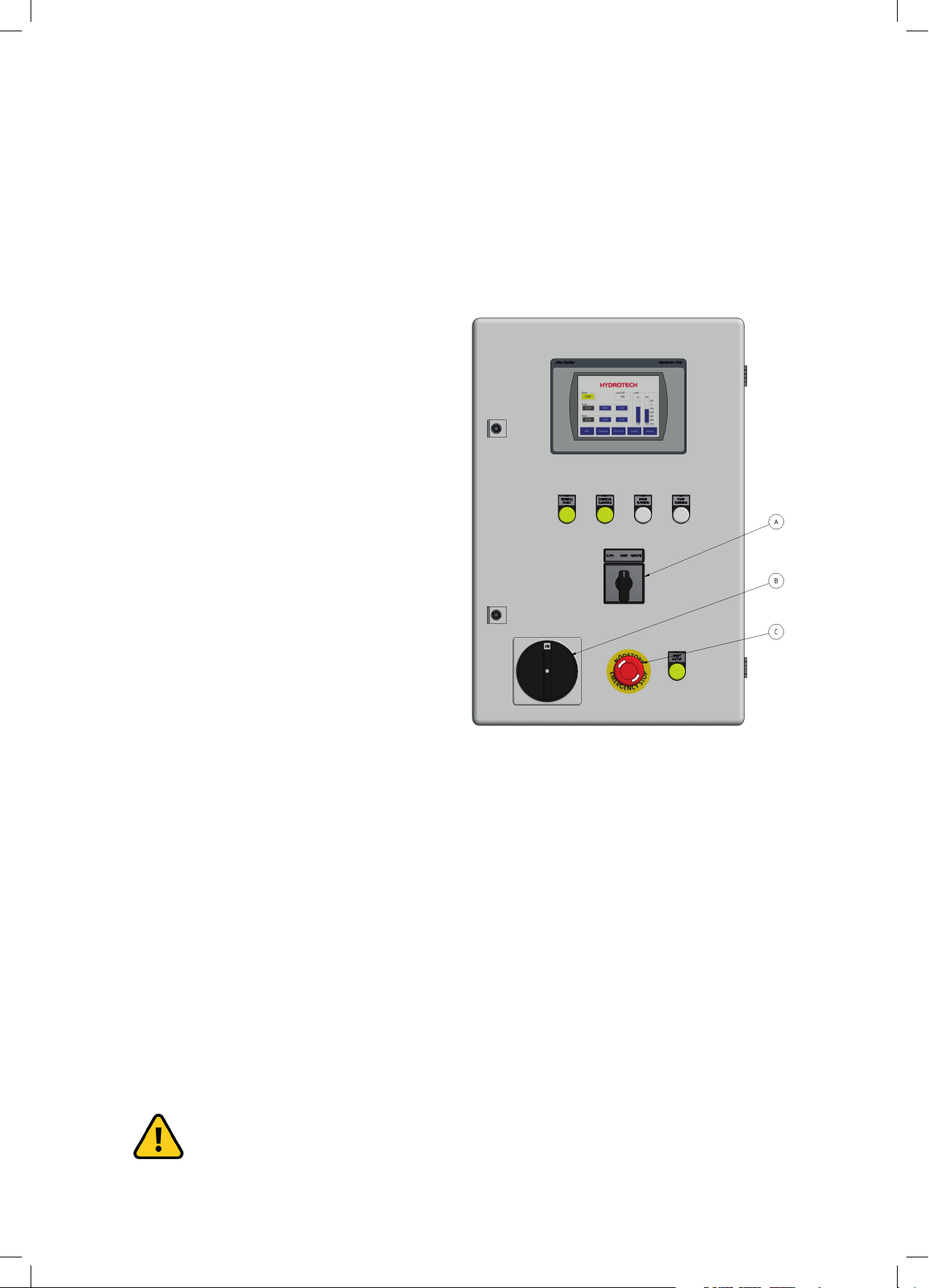
2.5 Emergency stop
The filter is equipped with an emergency stop
and a main switch (see the markings in Figure
2.3).
In the event of a power outage, turn the main
switch to the OFF position (0) to prevent the
filter drum from unintentionally starting when
the power returns.
2.6 Electrical safety
Electrical installation must be carried out by
a qualified electrician and in accordance with
local regulations. Also see Appendix A in the
“Automation manual”.
The filter tank must be connected to earth.
The main power switch/emergency switch must be fitted in accordance with applicable regulations.
Figur 2.3 Elskåp
A. Driftlägesomkopplare
B. Huvudbrytare
C. Nödstopp
2.7 Safety instructions
The filter is activated by turning the main power switch to the ON position (1), then selecting
AUTO, REMOTE or HAND mode using the operating mode selector located on the front of the
electrical cabinet.
NOTE! See instructions in section 5.1.
Turn the main power switch to the OFF (0) position and lock it with a padlock before per-
7
Page 8
Operation & maintenance manual, Discfilter HSF2600 - 1F series with PFLC
forming any work on the filter.
Access to the filter by unauthorized persons is strictly prohibited. Outdoor installations
must be fenced in.
The filter can start rotating without warning if automatic control is activated. Moving
parts must not be touched.
Safety guards are fitted around the power transmission. Make sure these are secured and correctly fitted.
The aerosols from the backwash water may contain harmful substances.
Measured noise levels from the filter are less than 74 dB(A). Personnel should use appropriate
protection, when necessary, in accordance with local regulations.
8
Page 9

Operation & maintenance manual, Discfilter HSF2600 - 1F series with PFLC
3. HYDROTECH DISCFILTER HSF2600-1F
3.1 Reception
Once the equipment has been delivered and received it must be checked for transport damage.
Document any transport damage before further handling of the equipment.
The consignment note, manual and spare part kit are attached to the equipment.
Check all parts against the consignment note. Some parts may be delivered unassembled. Handle fragile parts with care. Before lifting the equipment, see section 4.1.
3.2 Storage
Some precautions must be taken to prevent damage to equipment if a long storage time is necessary (several weeks or more).
⊲ The equipment should preferably be stored indoors, in a frost-free area.
⊲ The filter must be protected against direct sunlight if stored outdoors. Heat and UV radiation
can damage the filter panel and the control panel touch screen.
⊲ If the filters are delivered inside plastic covered wooden crates, a special type of corrosion may
occur if stored outdoors, especially in coastal areas. The moisture inside the plastic acts as an
anode and the exposed dry components as a cathode. In these areas, filters must therefore be
unpacked immediately upon delivery.
9
Page 10
Operation & maintenance manual, Discfilter HSF2600 - 1F series with PFLC
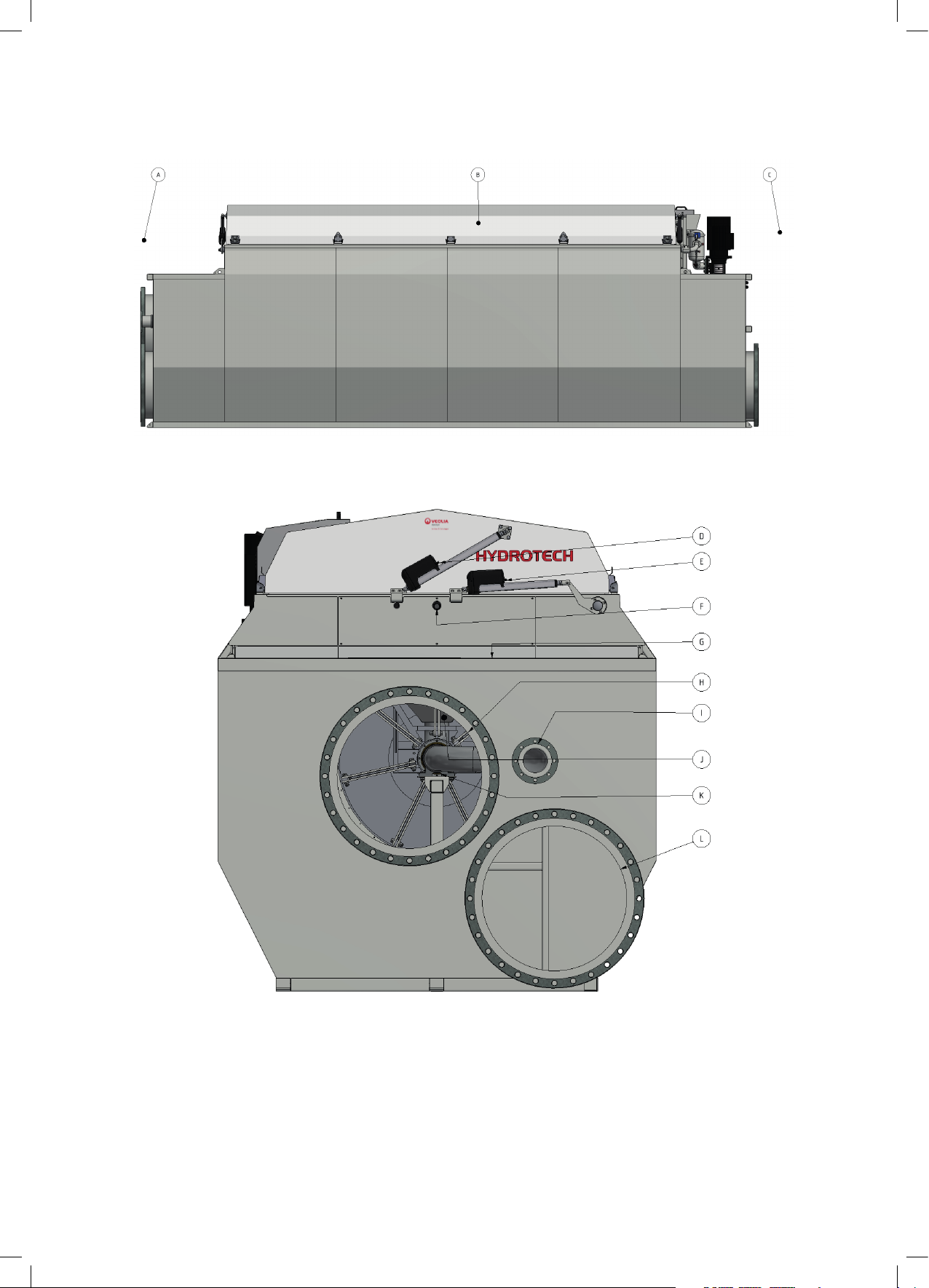
3.3 Overview
Figure 3.1 Hydrotech Discfilter in HSF2200 series type 1F (side view).
A. Inlet side
B. Filter cover
C. Outlet side
10
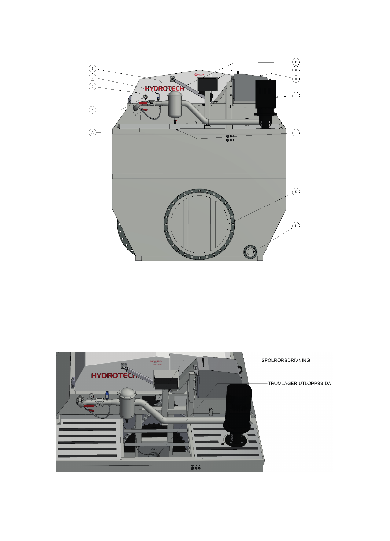
Figure 3.2 Hydrotech Discflter in HSF2600 series type 1F (from inlet side).
D. Actuator for opening cover
E. Actuator for backwash system servicing
F. Connection, chemical cleaning
G. Lubrication point
H. Inlet
I. Sludge outlet
J. Sludge trough
K. Drum bearing, inlet side
L. Outlet, separate emergency overflow (bypass) (option)
Page 11
Operation & maintenance manual, Discfilter HSF2600 - 1F series with PFLC
Figure 3.3 Hydrotech Discflter in HSF2600 series type 1F (from outlet side).
A. Bypass valve for nozzle check
B. Manometer
C. Shut off valve for wash pipe
D. Pressostat - dry run protector for pump
E. Backwash water filter
F. Actuator for opening cover
G. Junction box
H. Drive unit
I. Backwash pump
J. Lubrication point
K. Outlet
L. Drain (tank)
Figure 3.4 Hydrotech Discfilter in HSF2600 series type 1F from outlet side with a chequered plate and a cover plate
removed.
11
Page 12
Operation & maintenance manual, Discfilter HSF2600 - 1F series with PFLC
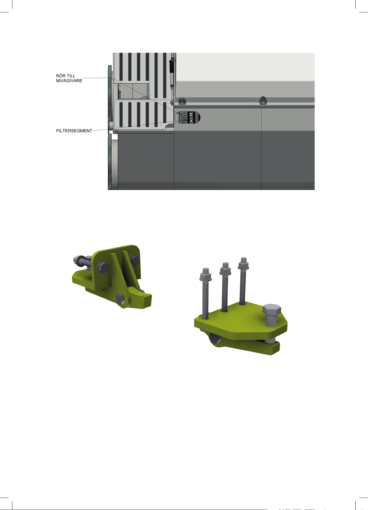
Figure 3.5 Hydrotech Discfilter in HSF2600 series type 1F with a chequered plate removed on the inlet side and a trans-
parent side plate. The level sensor behind the transparent side plate will be available once you lift the cover on the
backwash pipe side.
Two drum lifters are supplied unassembled for each installation, see Figure 3.6. These are only
used when servicing drum bearings. The supplier should be contacted when servicing bearings.
12
Figure 3.6 Drum lifter.
Page 13
Operation & maintenance manual, Discfilter HSF2600 - 1F series with PFLC
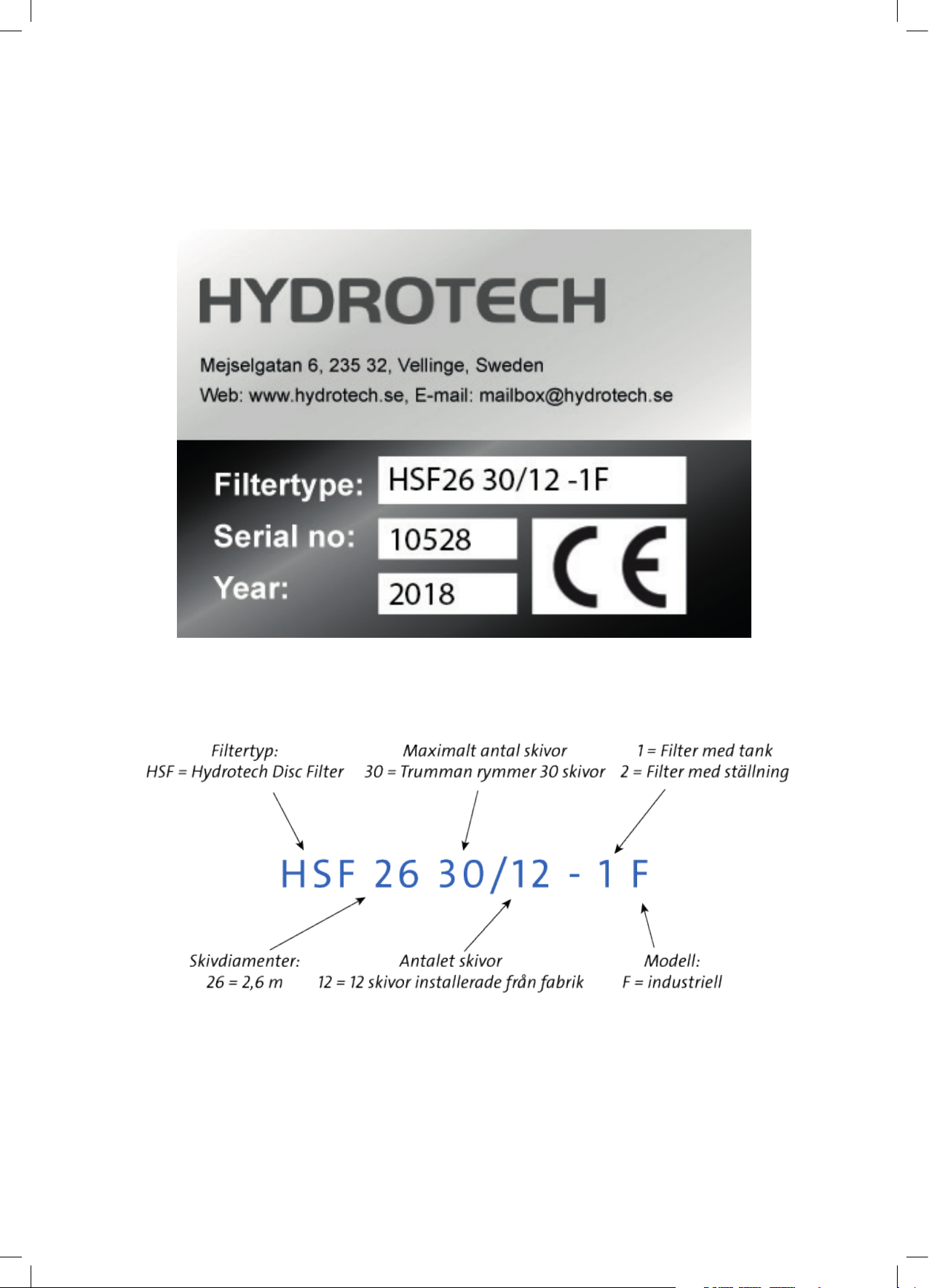
3.4 Identifying the filter
Filter type, serial number and year of manufacture are stated on the marking plate. The filter
type and serial number are also stated on the front of this manual.
Definition of filter designation:
Figure 3.7 Filter marking plate.
13
Page 14
Operation & maintenance manual, Discfilter HSF2600 - 1F series with PFLC
4. GENERAL INSTALLATION INSTRUCTIONS
4.1 Liing the equipment
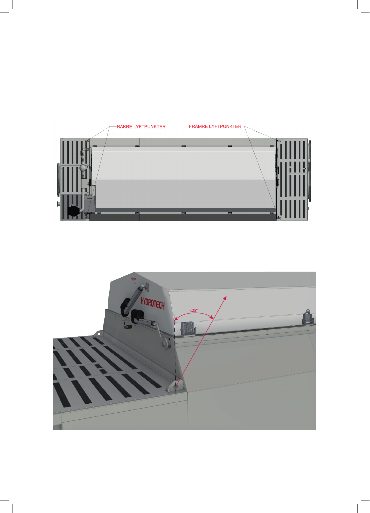
When lifting the tank, we recommend that you use the four lifting points on the tank, the placement of which is shown in Figure 4.1. The greatest permitted lifting angle is shown in Figure 4.2.
Figure 4.1 Placement of lifting points.
14
Figure 4.2 Largest permitted angle when lifting.
Page 15

Operation & maintenance manual, Discfilter HSF2600 - 1F series with PFLC
4.2 Installation site
4.2.1 Outdoor installation
In the event of outdoor installation it is important to protect the filter panels against direct sunlight, as heat and UV radiation can otherwise cause damage to the filter panels. The same applies
to the control panel touch screen.
The filter must be protected against frost. The filter cover provides sufficient protection at water
temperatures above +5 °C and air temperatures above -10 °C. At lower water and air temperatures, the filter installation must be carried out indoors.
4.2.2 Foundations
⊲ The filter must be installed on a flat surface
that offers sufficient load bearing capacity.
⊲ The filter is to be bolted to the foundation.
⊲ The filter must be level in both directions
(see Figure 4.3).
⊲ 600 mm wide aisles should be placed
around the filter to permit easy access to the
filter during servicing.
⊲ For reasons of safety, the space between the
filter and the concrete structure must be covered.
4.3 Electrical connection
Qualified electricians must perform all
electrical work.
Electrical connection must be done in accordance with local regulations. Check that the
settings on the motor protection correspond
with the motor data.
Figur 4.3 Filterinstallation.
Section 4.5 must be read before starting the filter's drum rotation.
4.4 Equipotential bonding
The Hydrotech Discfilter and associated equipment should be protected with a suitable system
for equipotential bonding. This is very important to prevent galvanic corrosion. Ideally use a ca-
15
Page 16

Operation & maintenance manual, Discfilter HSF2600 - 1F series with PFLC
ble with a cross section of 10-16 mm2. The cable should be connected to the same electrical potential as the drive system.
4.5 Checking the drum rotation and backwash pipe
Start up after electrical connection may only be carried out with a completely extended
backwash pipe.
1. Before starting the filter drum rotation, the backwash pipe should be extended as set out in
section 6.2.
2. Start drum rotation and check that the drum rotates in the same direction as the rotation arrow on the drive unit cover, see Figure 4.4.
Figure 4.4 Rotation arrow on the drive unit.
3. Reset the backwash pipe to operating mode.
4. Start drum rotation.
5. If necessary, check and adjust the height of the backwash pipe above the drum as set out in
section 7.4.
4.6 Pipe connections
Piping for reject should have a minimum inclination of 1%
16
Page 17

Operation & maintenance manual, Discfilter HSF2600 - 1F series with PFLC
5. START UP AND OPERATION
5.1 Check procedures during start-up
1. Check that the drive unit cover is installed correctly.
2. Set the mode selector to the HAND position (see F in Figure 5.2)
3. Set the main power switch to the ON (1) position (see I in Figure 5.2)
4. Start drum rotation on the operator panel
main menu (see Figure 5.1 and Figure 5.2).
5. Open the water supply a little so that the
water can slowly run into the filter drum. Make
sure that the difference in water level between
the inside and outside of the filter drum does
not exceed 450 mm (see section 5.2.1). If the filter cloth becomes clogged, it may be necessary
to fill the filter tank with water from an external source or to remove a filter panel and allow
unfiltered water to fill up the filter tank.
Figure 5.1 Main menu on electrical cabinet operator panel.
6. When the water level inside the filter tank exceed the pump suction pipe (or, if a CRK or MTR
pump has been installed, the pump), the pump must be started by pressing “Start” on the operator panel main menu (see Figure 5.1). NB Also read section 2.7.
7. When the water level inside the filter tank reaches the overflow wall, set the mode selector to
either REMOTE or AUTO (see section 5.2).
8. Open the water supply fully.
If the filter is operated using automatic level control, it may be necessary to calibrate the level
sensor in order for the filter to be run optimally (see “Automation manual HSF2600”).
17
Page 18

Operation & maintenance manual, Discfilter HSF2600 - 1F series with PFLC
5.2 Automatic seings
The control system for the HSF2600 series must always be equipped with a frequency converter
for the drive unit. This is factory calibrated if delivered from Hydrotech. To perform a soft start of
the drive motor, the frequency converter settings must be min. 5 sec “ramp up” and min. 3 sec
“ramp down”. The filter works with 50 Hz as standard.
If the filter is equipped with a Hydrotech standard control, the filter has three operating modes:
1. Automatic level control (AUTO mode).
2. Remote control (REMOTE mode).
3. Service mode (HAND mode).
18
Figure 5.2 Front side of electrical cabinet.
A. Operator panel
B. Warning lamp: Fault indicator
C. Warning lamp: Chemical cleaning
D. Indicator lamp: Drum operation
E. Indicator lamp: Pump operation
F. Mode selector (Auto/Hand/Remote)
G. Main power switch
H. Emergency stop
I. Reset button following emergency stop
Turn the mode selector to select the appropriate operating mode (see Figure 5.2, detail F).
Page 19

Operation & maintenance manual, Discfilter HSF2600 - 1F series with PFLC
5.2.1 Level dierences
The maximum permitted difference between
the water levels inside and outside of the drum
is 250 mm during normal operation (see figure
5.3). The recommended level difference is 100200 mm.
If an even flow after the filter is required, the
filter must be run with a small level difference.
The filter must be installed so that the
level difference in the event of operating disturbances under no circumstances exceeds 450 mm.
The filter shall be operated so that the level difference during normal operation does not
exceed 250mm.
Prolonged operation with a greater level difference will significantly shorten the life of the
filter panels and other vital parts.
Figure 5.3 Maximum permitted level difference during level
controlled operation.
5.2.2 Operating mode AUTO – Automatic level control
With automatic level control, drum rotation and the backwash pump are activated once the level difference between filtered and unfiltered water exceeds an adjustable value. The filter is
force-started if the filter has stood still for an extended period of time. If an external wash water
supply is used, the level sensor can control a solenoid valve instead of a pump.
The water level inside the drum will vary when AUTO mode has been selected. The water level is at its lowest immediately after a backwash cycle, and then rises until the level difference
between filtered and unfiltered water becomes too high.
5.2.3 Operating mode REMOTE – Remote control
In REMOTE operating mode, the filter can be controlled remotely. In remote control mode, the
filter can either be controlled as if in AUTO operating mode or using an external controller, see
the “Automation manual”.
5.2.4 Service mode HAND
HAND is only a service mode.
In order to operate the filter in HAND mode, the following steps must be implemented:
1. Turn the mode selector shown in Figure 5.2 to the HAND position.
19
Page 20

Operation & maintenance manual, Discfilter HSF2600 - 1F series with PFLC
2. Once the mode selector has been turned to
HAND, “HAND” will be shown in the operator panel main menu, see Figure 5.4. Press the
drum “Start” button - see Figure 5.4.
3. Press the pump “Start” button - see Figure
5.4.
The operator panel main menu also shows the
water levels of unfiltered (In) and filtered water
(Out), as well as the level difference between
them (Level Diff).
Figure 5.4 Main menu on electrical cabinet operator panel.
5.3 Backwash system
NOTE! Prior to servicing, read section 2.7.
The system pressure for backwashing must be set to 7-9 bar.
Newly connected pipe systems for external backwash water should be rinsed through before
they are connected to the filter. Thoroughly check that the nozzles are not blocked, see section
7.3.
20
Page 21

Operation & maintenance manual, Discfilter HSF2600 - 1F series with PFLC
6. FUNCTION
6.1 Intended use
The filter is designed and manufactured to remove solid particles in unpressurised water flow
systems. The filter is not a pressure vessel.
6.2 Non-approved use
Unless approved in writing by Hydrotech, the filter must not be used to filter liquids other than
water. The filter must not be installed in an environment with an explosive atmosphere or
another risk of explosion, such as high concentrations of dust.
6.3 Filtration and backwash process
A brief description of the process is given below.
1. The water to be filtered flows with gravity from the inside of the filter drum out to the filter
segments.
2. Solid particles are separated from the water using a filter medium attached to both sides of
the filter segments, whilst clean water passes through the filter medium to the outside of the
filter segment.
Figure 6.1 Disc filter function.
3. Operating mode AUTO – The solid particles trapped on the inside of the filter medium gradually reduce the water flow through the filter panel. The water level on the inside of the drum
begins to rise. Once the water reaches the level sensor, drum rotation and backwashing begin.
Operating mode REMOTE – The filter is controlled as in AUTO operating mode or using external
control (e.g. time-controlled drum rotation and backwashing). Service HAND – Drum rotation
and backwashing are started manually.
21
Page 22

Operation & maintenance manual, Discfilter HSF2600 - 1F series with PFLC
4. The backwash nozzles spray wash water on the outside of the filter panels. The solid particles
that accumulate are washed from the filter panels to the sludge channel, at the same time as
the drum rotates.
5. The removed particles and backwash water flow with gravity out of the filter.
22
Page 23

Operation & maintenance manual, Discfilter HSF2600 - 1F series with PFLC
7. MAINTENANCE/SERVICE
This chapter describes how maintenance and servicing is to be carried out. Chapter 8 describes
how often the various components require servicing.
7.1 Filter cover
NOTE! Prior to servicing, read section 2.7. The filter cover for the Hydrotech Discfilter HSF2600
series is controlled from the operator panel and can be opened in two directions depending on
which side of the filter needs to be accessed.
7.1.1 Hinge
Before the filter cover is operated from the operator panel, its hinge must be locked on the correct side. The locking pin (A) must lock the hinge lock (B) securely as shown in Figure 7.1a below.
Make sure that the filter cover is completely closed and that the hinge lock (B) shown in
Figure 7.1a surrounds the shaft (C) in Figure 7.1b.
The locking pin (A) and the hinge lock (B) must ALWAYS sit on the two outermost hinges (E), as
shown in Figure 7.2 or on the opposite side depending on which direction you want the cover to
open in.
Figure 7.1 a Locked hinge, b Open hinge
In order to access the backwash pipe, the hinges must be locked (E in Figure 7.2) on the side of the
cover on which the drive unit (F) sits (see Figure 7.2), and the hinges must be open (see Figure 7.1b)
on the opposite side, i.e. the backwash pipe side.
Figure 7.2 Shows the location of the lockable hinges and the drive unit.
23
Page 24

Operation & maintenance manual, Discfilter HSF2600 - 1F series with PFLC
7.1.2 Operating the filter cover
1. In order to operate the filter cover, the mode selector shown in Figure 7.3 must be in the “HAND”
position. When in HAND mode, “HAND” is shown in the operator panel main menu, see Figure
7.4 below.
2. Select “Login” (if the user is not already logged in) and log in using your user name and
password, see Figure 7.5 below.
3. Select “Service”.
4. Select “Cover & Spray”, see Figure 7.5.
Figure 7.3 Mode selector.
5. In the “Service Cover, Spray bar” window, there are 5 position sensors B3.1-B3.3 and B7.1-B7.2,
which indicate the position of the cover, see Figure 7.7. When the cover is closed, the “B3.1 - B7.1
Cover Closed” lights come on. In order to lift the filter cover, press the “Open” button until the
cover is completely open.
Check that the hinges are fully locked before opening the filter cover, see section “7.1.1
Hinge”.
24
Figure 7.4 Main menu on electrical cabinet operator panel. Figure 7.5 Service menu.
Figure 7.6 Login for service functions.
Figure 7.7 Service Cover & Spray bar menu.
6. When the cover is completely open on the backwash pipe side, the “B3.2 - B.7.2 Cover Open”
and “B3.3 Cover Open Service” lights come on, making it possible to extend the backwash pipe.
If the cover is fully open on the other side, only the “B3.2 – B7.2 Cover Open” light will come on.
When this is the case, the backwash pipe cannot be extended.
Page 25

Operation & maintenance manual, Discfilter HSF2600 - 1F series with PFLC
7.2 Extend the backwash pipe
NOTE! Prior to servicing, read section 2.7.
1. Turn the mode selector to “HAND” and lift
the filter cover on the backwash pipe side, see
section 7.1.
2. When the cover is fully opened on the backwash pipe side, B3.2, B3.3 and B7.2, as shown
in Figure 7.7 will come on. The backwash pipe
can now be extended, keep the “Out” button
as shown in Figure 7.7 pressed until the “B4.2
Spray bar Out” light comes on.
Figure 7.8 Filter cover is open and backwash pipe extended.
7.3 Backwash system
NOTE! Prior to servicing, read section 2.7.
The most common cause of disruption in the backwash system is nozzle clogging. Clogging is
caused by particles in the wash water and/or by e.g. biofouling in the pipe system.
7.3.1 Servicing nozzles
1. Open the cover on the side of the backwash pipe according to section 7.1.
2. Open the bypass valve (B) See Figure 7.9.
3. Click the Back arrow to go back a step, see Figure 7.10.
4. Select “Pump & Drum”, see Figure 7.11.
Figure 7.9 Main valve A and bypass valve B.
25
Page 26

Operation & maintenance manual, Discfilter HSF2600 - 1F series with PFLC
Figure 7.10 Service Cover & Spray bar menu. Figure 7.11 Service menu.
Maintain a safe distance from the filter whilst the drum is rotating
5. Select “Start” in the Drum window, see Figure 7.12.
6. Select “Start” in the Pump window, see Figure 7.12.
7. Close the main valve (A), see Figure 7.9.
8. Adjust the wash water flow using the bypass
valve so that there is a small constant flow
through the nozzles. This makes it easy to identify which nozzles need to be cleaned.
9. Press the back arrow.
10. Select “Cover & Spray”, see Figure 7.11.
Figure 7.12 Service Backwash Pump & Drum window.
26
11. Extend the wash ramp as described in section 7.2, point 2.
The operating time in this mode must be minimised in order to not risk the pump overheating.
12. Fully or partially clogged nozzles must be cleaned.
13. Remove the nozzle nut by turning it a ¼ turn anticlockwise. Do not lose the rubber seal
14. Clean the nozzle using compressed air or a plastic brush. Never use a steel brush or metal pins
as these may damage the nozzle.
15. Fit the nozzle in reverse order. Check that the nut has reached the stop position once it has
been tightened a ¼ turn clockwise.
Page 27

Operation & maintenance manual, Discfilter HSF2600 - 1F series with PFLC
Figure 7.13 Hydrotech backwash nozzles.
16. Stop drum rotation, (the pump stops automatically).
17. Open the wash water main valve and close the bypass valve.
18. Reset the backwash pipe to operating mode.
19. Close the filter cover
20. Start operations again as set out in section 5.1.
27
Page 28

Operation & maintenance manual, Discfilter HSF2600 - 1F series with PFLC
7.4 Backwash pipe position
NOTE! Prior to servicing, read section 2.7.
7.4.1 Checking backwash pipe position
1. Turn the mode selector to “HAND” and lift
the filter cover on the backwash pipe side, see
section 7.1.
2. Select “Start” for the drum on the operator
panel, see Figure 7.14.
Maintain a safe distance from the filter
whilst the drum is rotating.
3. When the drum rotates, the backwash pipe
moves slowly. Stop the drum rotation when
the backwash pipe is in its lowest position.
Figure 7.14 Main menu in operator manual.
Figur 7.15 Spolrörets lägsta position vid drift.
4. Check that the distance L min does not fall below 55 mm, see Figure 7.15.
If the distance L min falls below 55 mm, the equipment may suffer serious damage.
5. If necessary, adjust the position of the backwash pipe in accordance with section 7.4.2.
6. Adjust the backwash pipe safety stop in accordance with section 7.4.2.
7. Close the filter cover.
8. Start operations again as set out in section 5.1.
28
Page 29

Operation & maintenance manual, Discfilter HSF2600 - 1F series with PFLC
7.4.2 Checking backwash pipe position
1. Turn the main power switch to the OFF (0) position and lock with a padlock.
2. Undo the nut (B), see Figure 7.16.
3. Adjust the position of the backwash pipe using the screw (A).
Figure 7.16 Screw and nut for adjustment of backwash pipe position and backwash pipe safety stop
4. Secure the screw (A) using the nut (B).
5. Check backwash pipe position in accordance with section 7.4.1.
6. Adjust the backwash pipe safety stop in the corresponding way using the screw (C) and nut
(D). The screw must be set so that the distance L in Figure 7.15 cannot, under any circumstances,
be less than 55 mm.
7. Close the filter cover.
8. Start operations again as set out in section 5.1.
29
Page 30

Operation & maintenance manual, Discfilter HSF2600 - 1F series with PFLC
7.5 Cleaning the backwash water filter
NOTE! Prior to servicing, read section 2.7.
If the pressure gauge indicates a pressure that is more than 0.5 bar below normal pressure, it's
time to clean the backwash water filter.
1. Turn the main power switch to the OFF (0) position and lock with a padlock.
2. Drain the backwash water filter by opening the valve (A), see Figure 7.17.
3. Loosen the wing nut (B) and remove the clamp ring.
4. Lift off the backwash water filter cover (C).
5. Pull up and clean the filter insert.
6. Place the filter insert in the cover.
7. Refit the cover/filter insert and the clamping ring.
8. Close the drain valve (A).
9. Start operation in accordance with section 5.1.
30
Figure 7.17 Hydrotech backwash water filter.
A. Cover
B. Wing nut
C. Drainage
Page 31

Operation & maintenance manual, Discfilter HSF2600 - 1F series with PFLC
7.6 Bearings
NOTE! Prior to servicing, read section 2.7.
7.6.1 Lubrication of swivel
The swivel, the backwash pipe bearing, is located behind the cover plate on the outlet side and
connects the piping with the backwash pipe, see Figure 7.18.
When lubricating the swivel, the instructions below must be followed:
1. Lift up the red coloured cover shown in Figure 7.18 and hang it over the screw in the cover plate.
2. Lubricate the swivel using the recommended grease (see chapter 8).
3. Turn the cover back in front of the swivel lubrication nipple.
Figure 7.18 Swivel lubrication nipple.
7.6.2 Lubricating drum bearings
The bearings' lubrication nipples are fitted on the outside of the filter. Decals indicating the lubrication points are attached to the filter, see Figure
7.19. The lubrication points are also marked in Figure 3.2 and Figure 3.3.
The drum will rotate when the bearings are lubricated.
Lubricate the bearings using the recommended grease (see chapter 8).
Figur 7.19
31
Page 32

Operation & maintenance manual, Discfilter HSF2600 - 1F series with PFLC
7.6.3 Checking drum bearing wear
1. Turn the main power switch to the OFF (0) position and lock with a padlock.
2. Drain the filter tank.
3. Check the drum bearings for wear. If the distance between the bearing housing (A) and the
shaft (B) is less than 29 mm (see Figure 7.20), the drum bearing must be replaced.
4. Contact your supplier if the drum bearing needs to be replaced.
5. Start operation again in accordance with section 5.1..
Figure 7.20 Drum bearing on inlet side.
A. Bearing housing
B. Shaft
32
Page 33

Operation & maintenance manual, Discfilter HSF2600 - 1F series with PFLC
7.7 Filter panels
NOTE! Prior to servicing, read section 2.7.
7.7.1 High pressure cleaning
It may be necessary to manually clean the filter panels. It may be obvious that manual cleaning
is required as automatic backwashing starts on a more frequent basis. Manual cleaning can be
done using a high pressure washer.
1. Turn the mode selector to “HAND” and lift the filter cover on the backwash pipe side, see section 7.1.
2. Turn the main power switch to the OFF (0) position and lock with a padlock.
3. Clean the filter medium with water under high pressure.
When using a high pressure washer a wash pressure of max. 80 bar may be used. Never
hold the cleaning nozzle directly against the filter media.
4. Close the filter cover.
5. Start operations again as set out in section 5.1.
6. An automatic high pressure washer, controlled from the operator panel, is available as an optional extra. Contact your Hydrotech reseller.
33
Page 34

Operation & maintenance manual, Discfilter HSF2600 - 1F series with PFLC
7.7.2 Chemical cleaning of filter panels
Long-term clogging of the filter media can be caused by, among others, iron, calcium or organic fouling. This clogging can normally be removed through chemical cleaning. Three tried and
tested products that do not affect the lifespan of the filter medium are dilute hydrochloric acid
(HCl), dilute sodium hypochloride (NaClO) and dilute sodium hydroxide (NaOH).
The use of other types of cleaning agents may cause damage to equipment.
If HCl and NaClO mix, toxic chlorine gas forms. HCl and NaOH are highly corrosive. For
safety advice, see applicable local regulations.
For more detailed instructions, please contact your supplier.
Hydrotech Discfilter HSF2600 is equipped with a chemical ramp to enable cleaning of longterm
clogging of the filter panels. The dosing equipment (option) must be connected to the chemical
ramp connector, see Figure 7.21. The control system is prepared and programmed for connection
of a dosage system. Once electrical and mechanical installation has been completed, the control
system is to be operated as follows:
1. Turn the mode selector to “HAND”.
2. Select “Login” (if the user is not already logged in) and log in using your user name and
password.
3. Select “Chemical” on the operator panel, see Figure 7.22.
34
Figure 7.21 Connection to chemical ramp.
Page 35

Operation & maintenance manual, Discfilter HSF2600 - 1F series with PFLC
4. Follow the instructions set out in section 4.2.2 of the “Automatic Control System Manual”.
5. Once chemical cleaning has been completed, re-start operation as described in section 5.1.
Figure 7.22 Main menu on electrical cabinet operator panel.
35
Page 36

Operation & maintenance manual, Discfilter HSF2600 - 1F series with PFLC
7.7.3 Changing filter panels
It is important to maintain the balance of the
drum when changing filter panels. Remove/refit every other filter panel. This prevents unintentional rotation of the drum and reduces the
load on the drive chain and gearbox.
Figure 7.23 Correct way of changing filter panels.
NEVER remove or re-fit all filter panels on just ONE side of the disc, see Figure 7.23.
1. Turn the mode selector to “HAND” and lift the filter cover on the backwash pipe side, see section 7.1.
2. Select “Service” on the operator panel, see Figure 7.24.
Figure 7.24 Main menu on electrical cabinet operator
panel.
3. Select “Pump & Drum”, see Figure 7.25. Use
the “Jog Fwd” and “Jog Bwd” buttons to set the
drum in the desired mode, see Figure 7.26.
4. Turn the main power switch to the OFF (0)
position and lock with a padlock.
5. Undo the filter segment cover screw and remove the cover, see Figure 7.27.
6. Pull out the filter panel.
7. Insert a new filter panel and press in until it
touches the bottom.
The filter panels MUST be installed with the filter medium inwards and the frame outwards
as shown in Figure 7.28.
Figure 7.25 Service menu.
Figur 7.26 ”Service Backwash Pump & Drum”- fönstret.
36
8. Re-fit the filter segment cover (see Figure 7.27) and tighten the screw.
Maximum tightening torque: 3 Nm.
Page 37

Operation & maintenance manual, Discfilter HSF2600 - 1F series with PFLC
9. Close the filter cover.
10. Start operations again as set out in section 5.1.
Figure 7.27 Installation of filter segment cover.
Figure 7.28 Location of filter panels.
37
Page 38

Operation & maintenance manual, Discfilter HSF2600 - 1F series with PFLC
7.8 Drive chain
NOTE! Prior to servicing, read section 2.7.
The filter is equipped with a chain drive. For technical data, see Appendices A and D.
7.8.1 Checking the drive chain
1. Turn the mode selector to “HAND” and lift the filter cover on the same side as the drive unit,
see section 7.1.
2. Turn the main power switch to the OFF (0) position and lock with a padlock.
3. Turn the drum by hand in the direction of rotation in order to stretch the chain.
4. Check the tension of the chain return; it must be possible to move it between 50-75 mm, see
figure.
38
Figure 7.29 Filter drive unit.
5. If necessary, adjust the chain in accordance with section 7.8.2.
6. Close the filter cover.
7. Start operations again as set out in section 5.1.
Page 39

Operation & maintenance manual, Discfilter HSF2600 - 1F series with PFLC
7.8.2 Adjusting drive chain tension
Adjust drive chain tension as follows:
1. Turn the main power switch to the OFF (0)
position and lock with a padlock.
2. Loosen the four nuts (A). See Figure 7.30.
3. Loosen the nut (B).
4. Adjust the tension of the chain using the
screw (C).
5. Secure the screw (C) using the nut (B).
6. Tighten the four nuts (A).
7. Close the filter cover
Figure 7.30 Engine suspension plate.
8. Start operations again as set out in section 5.1.
When the drive chain cannot be adjusted any more, the chain is worn and must be replaced, see
section 7.8.3.
7.8.3 Replacing the drive chain
1. Turn the main power switch to the OFF (0) position and lock with a padlock.
2. Lower the drive unit to its lowest position, see section 7.8.2.
3. Split and remove the drive chain. The drive chain can be separated in all links.
4. Fit the new drive chain.
5. Adjust drive chain tension in accordance with section 7.8.2.
6. Start operation again in accordance with section 5.1.
39
Page 40

Operation & maintenance manual, Discfilter HSF2600 - 1F series with PFLC
7.9 Drive unit
NOTE! Prior to servicing, read section 2.7.
For information about the drive unit, see Appendix D.
7.10 Inlet seal
NOTE! Prior to servicing, read section 2.7.
7.10.1 Checking inlet seal
1. Turn the main power switch to the OFF (0)
position and lock with a padlock.
2. Lower the water level in the filter until the
whole inlet seal is accessible.
3. Check the inlet seal for damage and wear,
see Figure 7.31.
4. If necessary, replace the inlet seal in accordance with section 7.10.2.
5. Start operation again as set out in section 5.1.
Figure 7.31 Check of inlet seal.
7.10.2 Replacing the inlet seal
1. Turn the main power switch to the OFF (0) position and lock with a padlock.
2. Lower the water level in the filter until the whole inlet seal is accessible.
3. Note how the inlet gasket is fitted before it is dismantled.
4. Loosen the screws and nuts holding the inlet gasket in position.
5. Remove the inlet seal.
6. Fit a new inlet seal.
40
7. Start operations again as set out in section 5.1.
Page 41

Operation & maintenance manual, Discfilter HSF2600 - 1F series with PFLC
8. MAINTENANCE SCHEDULE
CHECK/ACTION MAINTENANCE INTERVAL
Check whether the backwash water filter is clog-
ged. See section 7.5.
Check the filter panels for clogging and damage,
see section 7.7.
Inspect the inside of the filter: Make sure no large objects that can get caught in the drum, filter
segments or sludge trough have entered the filter.
Also check that the reject does not accumulate
(sediment) in the sludge trough.
NOTE! Prior to servicing, read section 2.7. Remove
large objects and rinse the sludge trough.
WARNING! Turn the main power switch to
the OFF position and lock with a padlock.
Rinse the metal surfaces of the filter structure
with clean water. Clean (uncontaminated) metal
surfaces minimize corrosion, particularly in salt
water applications.
The interval is based on experience from the
application in question. (When the wash water
pressure drops 0.5 bar below the normal value.)
Once a week, or at another interval based on ex-
perience from the application in question.
Once a week or another interval based on expe-
rience from the application in question.
Twice a month or another interval based on ex-
perience from the application in question.
Check the nozzles with respect to clogging. See
section 7.3.
Lubricate the swivel to the backwash pipe using
grease of the type NLGI:2 (e.g. Molykote Multilub,
Rembrandt EP or equivalent grease). See section
7.6.1.
Lubricate the drum bearings (on the inlet and drive side) using grease of the type NLGI:2 (e.g. Molykote Multilub, Rembrandt EP or equivalent grea-
se). See section 7.6.2.
Check drive chain tension and condition. See sec-
tion 7.8.
Check backwash pipe position, see section 7.4. Twice a year.
Check drive unit oil level, see section 7.9. Twice a year.
Check drum bearing wear, see section 7.6.3. Once a year.
Check inlet seal, see section 7.10. Once a year.
Twice a month or another interval based on ex-
perience from the application in question.
Twice a month with continuous drum rotation.
Once a month with intermittent drum opera-
tion.
Twice a month with continuous drum rotation.
Once a month with intermittent drum opera-
tion.
Four times a year with continuous drum rotation. Twice a year with intermittent drum rota-
tion.
Change the gearbox oil. Oil type: ISO viscosity VG
680 (e.g. Omala oil 680 (Shell) or equivalent gear-
box oil). Also see Appendix D.
See Appendix D.
41
Page 42

Operation & maintenance manual, Discfilter HSF2600 - 1F series with PFLC
Symbols used on Hydrotech filters
Symbol is displaying equipotential
earth bonding points on the filter.
Symbol shown at lubrication points
on the filter. Read the manual for further information about lubrication.
Symbol displaying moving parts. Negligence to comply with safety regulations may lead to injury.
This symbol is placed where certain
attention is needed when handling
the filter. Read the manual for further
information.
Warning for high voltage. Always assume all electrical equipment to be live
and
Used as a warning where corrosive
fluids is used. Always use appropriate
safety equipment when handling corrosive products.
42
Page 43

Operation & maintenance manual, Discfilter HSF2600 - 1F series with PFLC
Manuals & technical information
For further technical information please visit http://technomaps.veoliawatertechnologies.com/
hydrotech/en/. Click on ”Manuals & technical information” in the list on the left side.
Hydrotech microscreen filters webpage
Select the product you want more information about and it will open a Pdf in a new tab. You can
also find information regarding products used on Hydrotech filters, e.g. motors, pumps, actuators etc.
43
Page 44

44
Operation & maintenance manual, Discfilter HSF2600 - 1F series with PFLC
Hydrotech AB
A Veolia Solutions & Technologies Company
Mejselgatan 6
235 32 Vellinge
Sverige
Telefon: +46 (0)40 - 42 95 30
Fax: +46 (0)40 - 42 95 31
E-mail: mailbox@hydrotech.se
Hemsida: www.hydrotech.se
Copyright © All rights reserved
 Loading...