

Hydrotech HSF2600, HSF2600-1F Operation And Maintenance Manual

Discfilter HSF 26 - 1F series PFLC
Operation and maintenance manual
Revised:2018-05-23

Operation & maintenance manual, Discfilter HSF2600 - 1F series with PFLC
LIST OF CONTENTS
1. INTRODUCTION 5
2. SAFETY INSTRUCTIONS 6
2.1 Warning symbols 6
2.2 CE marking 6
2.3 Conversion 6
2.4 Demands on personnel 7
2.5 Emergency stop 7
2.6 Electrical safety 7
2.7 Safety instructions 7
3. HYDROTECH DISCFILTER HSF2600-1F 9
3.1 Reception 9
3.2 Storage 9
3.3 Overview 10
3.4 Identifying the filter 13
4. GENERAL INSTALLATION INSTRUCTIONS 14
4.1 Liing the equipment 14
4.2 Installation site 15
4.2.1 Outdoor installation 15
4.2.2 Foundations 15
4.3 Electrical connection 15
4.4 Equipotential bonding 15
4.5 Checking the drum rotation and backwash pipe 16
4.6 Pipe connections 16
2

Operation & maintenance manual, Discfilter HSF2600 - 1F series with PFLC
5. START UP AND OPERATION 17
5.1 Check procedures during start-up 17
5.2 Automatic seings 18
5.2.1 Level dierences 19
5.2.2 Operating mode AUTO – Automatic level control 19
5.2.3 Operating mode REMOTE – Remote control 19
5.2.4 Service mode HAND 19
5.3 Backwash system 20
6. FUNCTION 21
6.1 Intended use 21
6.2 Non-approved use 21
6.3 Filtration and backwash process 21
7. MAINTENANCE/SERVICE 23
7.1 Filter cover 23
7.1.1 Hinge 23
7.1.2 Operating the filter cover 24
7.2 Extend the backwash pipe 25
7.3 Backwash system 25
7.3.1 Servicing nozzles 25
7.4 Backwash pipe position 28
7.4.1 Checking backwash pipe position 28
7.4.2 Checking backwash pipe position 29
7.5 Cleaning the backwash water filter 30
7.6 Bearings 31
7.6.1 Lubrication of swivel 31
3

Operation & maintenance manual, Discfilter HSF2600 - 1F series with PFLC
7.6.2 Lubricating drum bearings 31
7.6.3 Checking drum bearing wear 32
7.7 Filter panels 33
7.7.1 High pressure cleaning 33
7.7.2 Chemical cleaning of filter panels 34
7.7.3 Changing filter panels 36
7.8 Drive chain 38
7.8.1 Checking the drive chain 38
7.8.2 Adjusting drive chain tension 39
7.8.3 Replacing the drive chain 39
7.9 Drive unit 40
7.10 Inlet seal 40
7.10.1 Checking inlet seal 40
7.10.2 Replacing the inlet seal 40
8. MAINTENANCE SCHEDULE 41
Symbols used on Hydrotech filters 42
Manuals & technical information 43
4

Operation & maintenance manual, Discfilter HSF2600 - 1F series with PFLC
1. INTRODUCTION
This manual contains instructions for the operation of Hydrotech Discfilter in the HSF2600 series, type 1F (tank filter).
Pay attention to all warning symbols that appear in this manual. If this information is ignored it
may result in serious personal injury and/or damage to equipment.
The manual must always be available to the personnel working with the equipment.
It is important that:
⊲ The manual and other relevant documents are kept throughout the life of the equipment. The
manual and other relevant documents are a part of the equipment.
The following documents (manuals) are a part of the equipment:
▹ Operation & Maintenance Manual
▹ Automation manual
⊲ All applicable personnel must read the manuals carefully.
5
Operation & maintenance manual, Discfilter HSF2600 - 1F series with PFLC
2. SAFETY INSTRUCTIONS
Hydrotech Discfilters in the HSF2600 series are designed for safe operation provided that they are
installed correctly and used in accordance with the enclosed instructions. The equipment must
be installed correctly and adapted in accordance with local regulations. The machine equipment
is intended for use by multiple operators. You must read the applicable chapters in this manual
prior to using the equipment or performing maintenance.
⊲ Pay attention to all warning symbols that appear in this manual. If this information is ignored
it may result in serious personal injury and/or damage to equipment.
⊲ Assume all electrical equipment to be live.
⊲ Assume all hoses and pipes to be pressurized.
⊲ Before carrying out maintenance work, the main power switch (see Figure 2.3) must be turned
to the OFF (0) position and locked with a padlock.
⊲ Maintenance and service may only be performed by authorised personnel.
⊲ Adequate lighting should be used while operating the filter and when working in close prox-
imity to the filter.
2.1 Warning symbols
Figur 2.1
Warning symbols are used in this manual to draw attention to potentially dangerous situations:
Information that warns you of a potential risk of personal injury and/or damage to equipment.
Warning decals (see Figure 2.1) are attached to the filter to warn personnel and serve as a reminder to keep hands and fingers away from moving parts of the filter.
2.2 CE marking
Figur 2.2
This equipment is CE marked (see Figure 2.2), which guarantees that the equipment is designed,
manufactured and described in accordance with the requirements set out in the EU Machinery
Directive.
2.3 Conversion
The CE marking does not include any components that are not approved by Hydrotech AB and
which are used in conversion/reconstruction of the equipment.
The warning symbols and CE marking must be attached where they are fully visible. If any part of
6
Operation & maintenance manual, Discfilter HSF2600 - 1F series with PFLC
the equipment with a warning symbol is replaced, a new symbol must be attached in the same
position. Damaged symbols and CE markings must be replaced immediately.
2.4 Demands on personnel
Only personnel trained for the equipment and conversant with local regulations may perform
service and maintenance, in order to avoid personal injury and damage to the equipment. Service and maintenance personnel may only handle those parts of the equipment they have been
trained for.
The operator may need to work inside the safety barrier and in the safety zone during maintenance and set-up before operation.
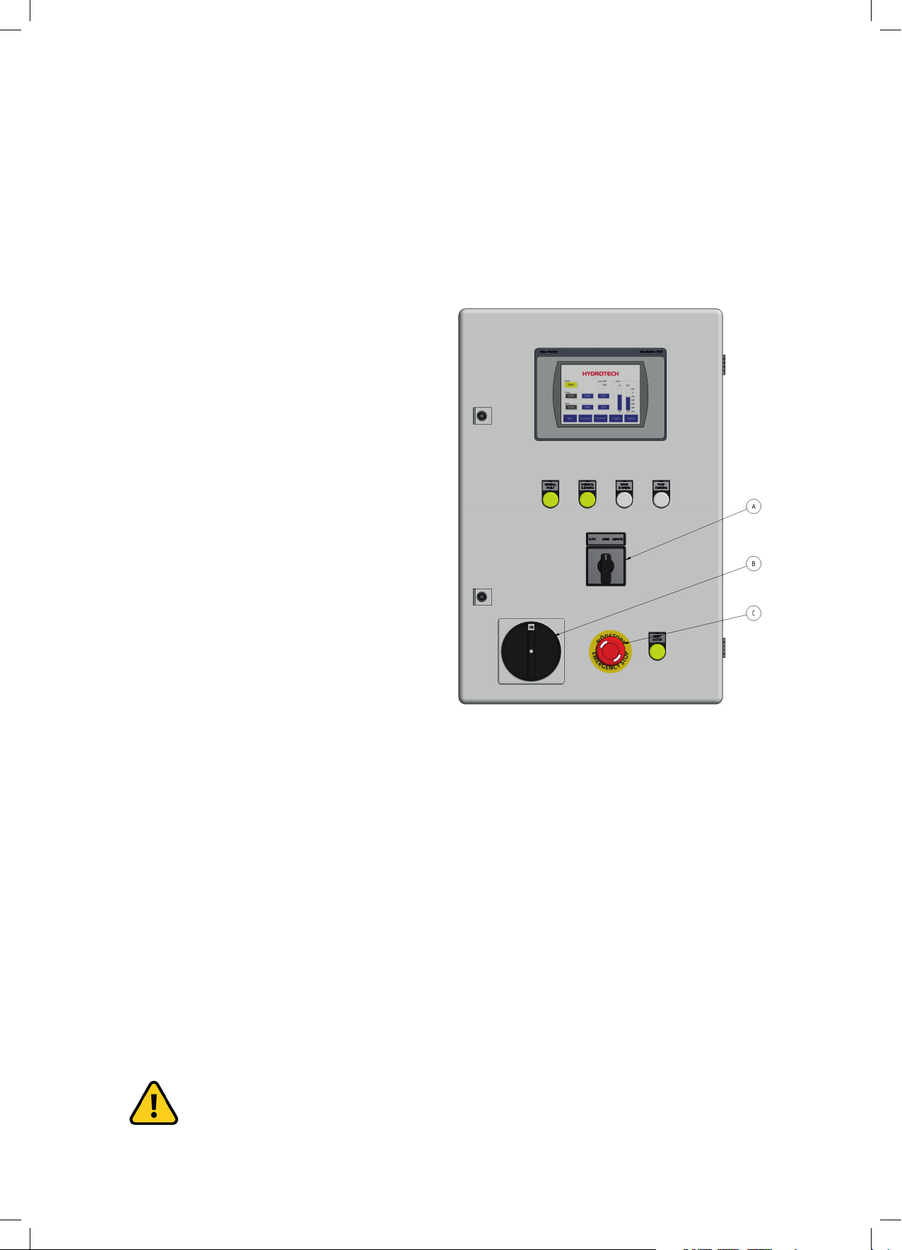
2.5 Emergency stop
The filter is equipped with an emergency stop
and a main switch (see the markings in Figure
2.3).
In the event of a power outage, turn the main
switch to the OFF position (0) to prevent the
filter drum from unintentionally starting when
the power returns.
2.6 Electrical safety
Electrical installation must be carried out by
a qualified electrician and in accordance with
local regulations. Also see Appendix A in the
“Automation manual”.
The filter tank must be connected to earth.
The main power switch/emergency switch must be fitted in accordance with applicable regulations.
Figur 2.3 Elskåp
A. Driftlägesomkopplare
B. Huvudbrytare
C. Nödstopp
2.7 Safety instructions
The filter is activated by turning the main power switch to the ON position (1), then selecting
AUTO, REMOTE or HAND mode using the operating mode selector located on the front of the
electrical cabinet.
NOTE! See instructions in section 5.1.
Turn the main power switch to the OFF (0) position and lock it with a padlock before per-
7
Operation & maintenance manual, Discfilter HSF2600 - 1F series with PFLC
forming any work on the filter.
Access to the filter by unauthorized persons is strictly prohibited. Outdoor installations
must be fenced in.
The filter can start rotating without warning if automatic control is activated. Moving
parts must not be touched.
Safety guards are fitted around the power transmission. Make sure these are secured and correctly fitted.
The aerosols from the backwash water may contain harmful substances.
Measured noise levels from the filter are less than 74 dB(A). Personnel should use appropriate
protection, when necessary, in accordance with local regulations.
8

Operation & maintenance manual, Discfilter HSF2600 - 1F series with PFLC
3. HYDROTECH DISCFILTER HSF2600-1F
3.1 Reception
Once the equipment has been delivered and received it must be checked for transport damage.
Document any transport damage before further handling of the equipment.
The consignment note, manual and spare part kit are attached to the equipment.
Check all parts against the consignment note. Some parts may be delivered unassembled. Handle fragile parts with care. Before lifting the equipment, see section 4.1.
3.2 Storage
Some precautions must be taken to prevent damage to equipment if a long storage time is necessary (several weeks or more).
⊲ The equipment should preferably be stored indoors, in a frost-free area.
⊲ The filter must be protected against direct sunlight if stored outdoors. Heat and UV radiation
can damage the filter panel and the control panel touch screen.
⊲ If the filters are delivered inside plastic covered wooden crates, a special type of corrosion may
occur if stored outdoors, especially in coastal areas. The moisture inside the plastic acts as an
anode and the exposed dry components as a cathode. In these areas, filters must therefore be
unpacked immediately upon delivery.
9
Operation & maintenance manual, Discfilter HSF2600 - 1F series with PFLC
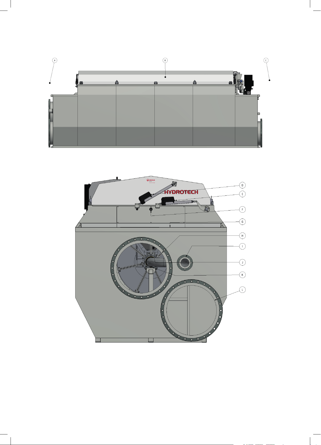
3.3 Overview
Figure 3.1 Hydrotech Discfilter in HSF2200 series type 1F (side view).
A. Inlet side
B. Filter cover
C. Outlet side
10
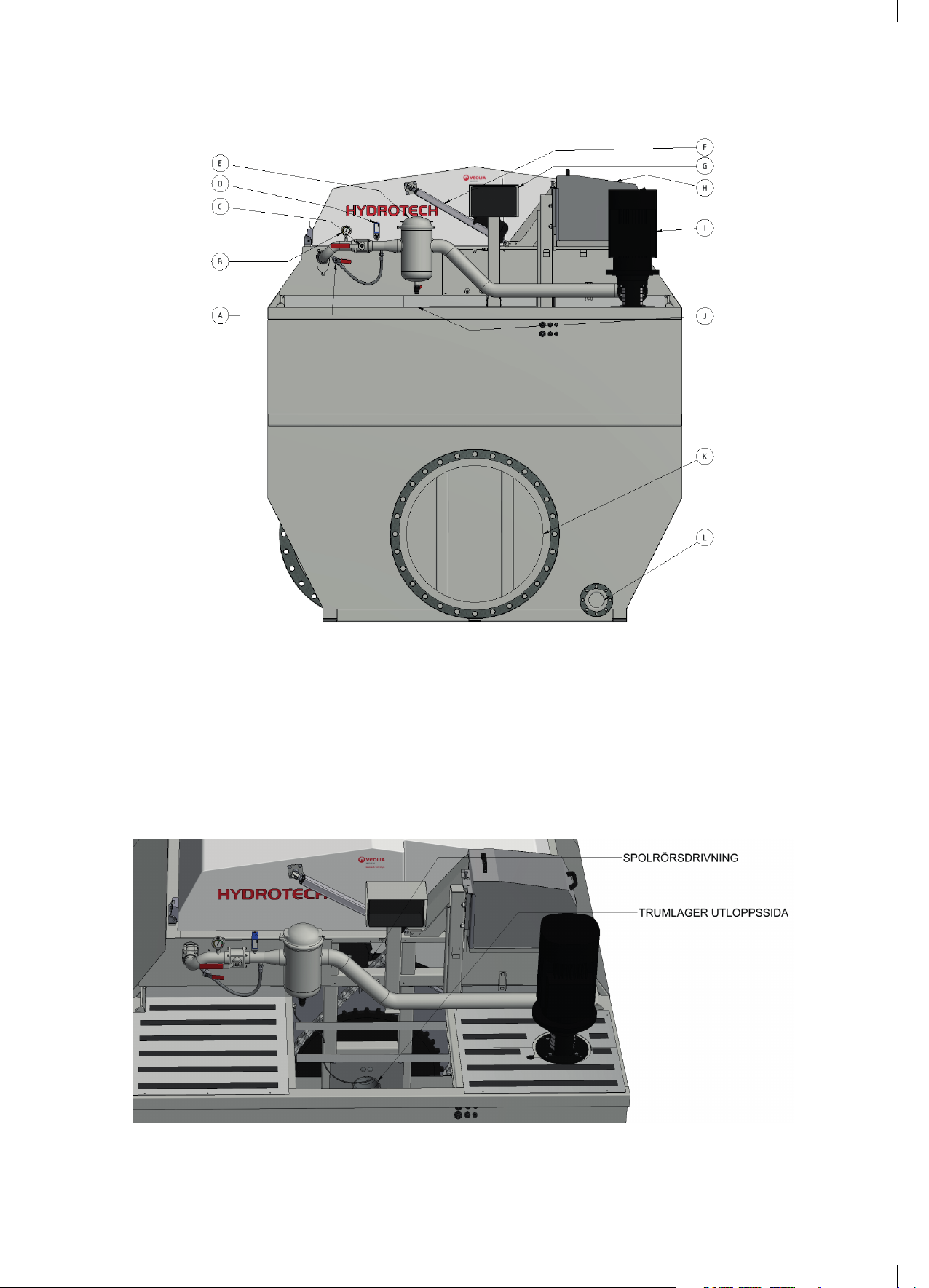
Figure 3.2 Hydrotech Discflter in HSF2600 series type 1F (from inlet side).
D. Actuator for opening cover
E. Actuator for backwash system servicing
F. Connection, chemical cleaning
G. Lubrication point
H. Inlet
I. Sludge outlet
J. Sludge trough
K. Drum bearing, inlet side
L. Outlet, separate emergency overflow (bypass) (option)
Operation & maintenance manual, Discfilter HSF2600 - 1F series with PFLC
Figure 3.3 Hydrotech Discflter in HSF2600 series type 1F (from outlet side).
A. Bypass valve for nozzle check
B. Manometer
C. Shut off valve for wash pipe
D. Pressostat - dry run protector for pump
E. Backwash water filter
F. Actuator for opening cover
G. Junction box
H. Drive unit
I. Backwash pump
J. Lubrication point
K. Outlet
L. Drain (tank)
Figure 3.4 Hydrotech Discfilter in HSF2600 series type 1F from outlet side with a chequered plate and a cover plate
removed.
11
Operation & maintenance manual, Discfilter HSF2600 - 1F series with PFLC
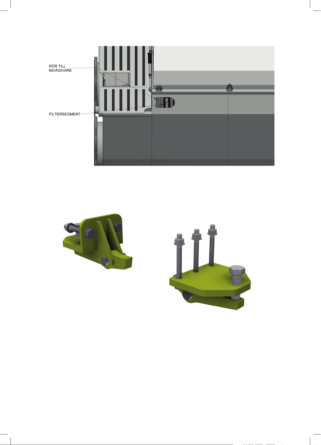
Figure 3.5 Hydrotech Discfilter in HSF2600 series type 1F with a chequered plate removed on the inlet side and a trans-
parent side plate. The level sensor behind the transparent side plate will be available once you lift the cover on the
backwash pipe side.
Two drum lifters are supplied unassembled for each installation, see Figure 3.6. These are only
used when servicing drum bearings. The supplier should be contacted when servicing bearings.
12
Figure 3.6 Drum lifter.
Operation & maintenance manual, Discfilter HSF2600 - 1F series with PFLC
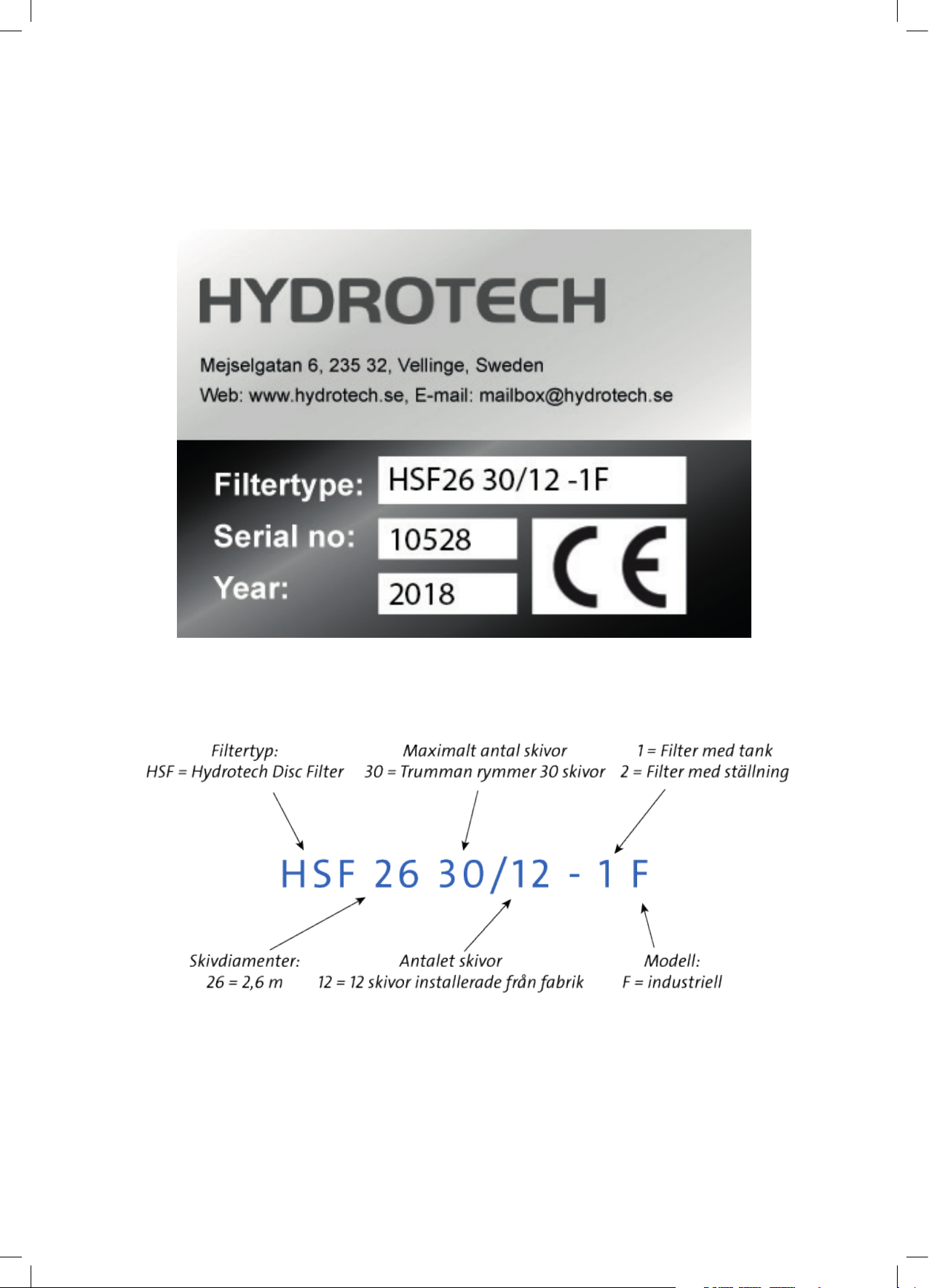
3.4 Identifying the filter
Filter type, serial number and year of manufacture are stated on the marking plate. The filter
type and serial number are also stated on the front of this manual.
Definition of filter designation:
Figure 3.7 Filter marking plate.
13
Operation & maintenance manual, Discfilter HSF2600 - 1F series with PFLC
4. GENERAL INSTALLATION INSTRUCTIONS
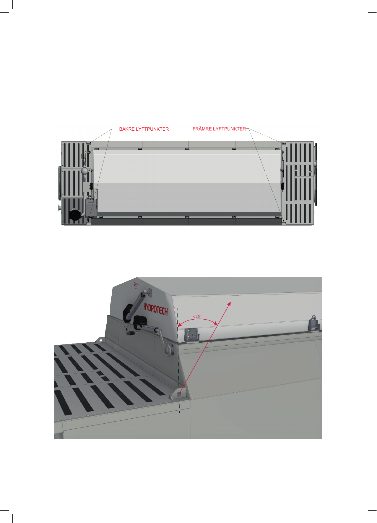
4.1 Liing the equipment
When lifting the tank, we recommend that you use the four lifting points on the tank, the placement of which is shown in Figure 4.1. The greatest permitted lifting angle is shown in Figure 4.2.
Figure 4.1 Placement of lifting points.
14
Figure 4.2 Largest permitted angle when lifting.
 Loading...