

Page 1

Item #26117
#51450 Rev. 8/08
ULTRA 2 UNDER SINK FILTER INSTALLATION INSTRUCTIONS
Ultra 2 Parts include:
1 Two housing bracket c/w housing and cartridges
1 5 foot length 1/4” OD blue tubing (product water)
1 5 foot length 1/4” OD white tubing (feed water)
Package A
2 Phillips #10 x 3/4” stainless steel screws
2 1/4” plastic tubing inserts
2 Elbow, 1/4” x 1/4”, QC x MNPT
1 Filter housing wrench
1 SV9 self tapping feed water saddle c/w quick connect tube
fitting
Package B
1 Long reach faucet assembly c/w quick connect tube fitting
Limited Warranty
• This warranty is valid for twelve months from date of purchase.
If this product is found to be defective in the judgement of the
manufacturer, a like or similar product will be provided at no
charge.
• The manufacturer shall not be liable for damages or delays
caused by defective material or workmanship or by failure due
to normal wear.
• Retain for your records along with your proof of purchase.
Precautions
• This filter is designed to operate at water pressure up to 100
psi. Normal municipal water pressure is 40 - 60 psi.
• Plastic housing parts must not be subjected to freezing,
excessive heat or direct sunlight. These conditions may cause
failure.
• Install filter with a minimum of 3” clearance - top, bottom and
sides.
• Do not overtighten fittings when installing this unit.
Replacement Cartridges
Carbon Filter #26006
- Replace a minimum of every six months or as
required.
- Carbon filters require some rinsing to remove
carbon fines before installation.
Post-filter #26118 - 0.5 Micron Carbon Briquette
Cartridge
- Replace a minimum of every 12 months or if
production or quality of water diminishes.
Page 2
ULTRA 2 UNDER SINK FILTER INSTALLATION INSTRUCTIONS
This unit is not intended for use where water is microbiologically unsafe or with
water of unknown quality without adequate disinfection before or after the unit.
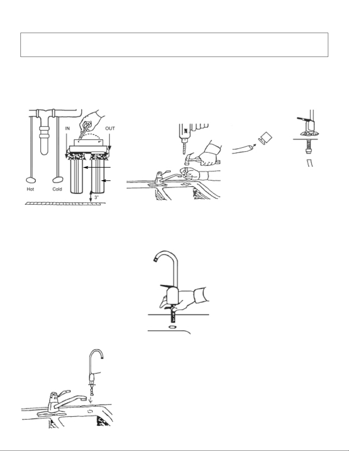
Step 1 - Choose a Location
Position the filter housing bracket on wall
of cabinet nearest cold water line
beneath sink. Leave at least 3” clearance
between the bottom of the filter housing
and the floor. Mark bracket slots on the
wall.
Step 2 - Install Filter Cartridges
For sanitization procedures, refer to
Instructions #1. Install the Carbon filter in
the (1) sump and 0.5 Micron Carbon
Briquette cartridge in the (2) sump.
Step 3 - Install Screws - Package A
Drill a 1/8” hole on each mark, then insert
the screws. Leave each screw
approximately 1/4” out from the wall for
mounting the head assembly later in the
installation.
Step 4 - Installing the Ultra 2 Faucet
The faucet may be installed into the hole
normally used for the sink sprayer. If you
have a sink sprayer installed and plan to
use it or do not have a hole, you will
have to drill a hole for the faucet. The
faucet will fit through a 7/16” hole or
larger.
For drilling through a metal sink, first
make a small indentation with a punch
where you want to install the faucet.
(Caution - Wear Eye Protection When
Drilling)
For drilling through porcelain, place a
piece of masking tape over the location,
then score with a punch before drilling.
Step 5 - Insert the Faucet - Package B
Remove the hardware from the faucet
stem for later use. Slide the large chrome
plated washer onto the stem, then the
large plastic washer. Place the faucet
stem through the hole on the sink.
Step 6 - Secure the Faucet
Slide the small rubber washer, then the
large metal washer and lock nut onto the
faucet stem. Tighten the lock nut to
secure the faucet in place.
Step 7 - Install Faucet Connector
Apply NSF 61 grade tape over the
threads of the faucet and install the
faucet connector. Do not overtighten.
Step 8 - Connect the Product Water
Tubing
Firmly push one end of the blue product
water tubing into the quick connect fitting
of faucet connector as shown below. For
more details on quick connect fitting, see
instruction #2.
Step 9 - Install Feed Water Saddle Package A
Locate a suitable area on the cold line.
Following the instructions #3 supplied,
attach the self tapping feed water saddle
to the cold water line.
Step 10 - Install Connector and the
Feed Water Tubing
Install the connector (PACKAGE A) to the
valve body of the saddle valve as shown
in step 7 (If not using compression nut
fittings). Firmly push the one end of the
white tubing to the quick connect fitting of
the connector as shown in Step 8.
Step 11 - Install White 90 Degree
Elbows
Apply NSF 61 grade tape to the threads
of the white 90 degree elbow fitting and
install them in the filter inlet and outlet
ports.
Step 12
Firmly push the other end of white tubing
and the other end of the blue tubing into
the quick connect fittings of elbow at the
inlet and outlet side respectively. For
more details on quick connect fittings,
see instructions # 2.
Step 13 - Activating the System
Open feed water saddle and faucet.
Flush unit for 2 - 3 minutes or until all the
air has been expelled and the water
appears clear at the faucet.
(1)
(2)
Page 3

Instruction #1 - Cleaning, Sanitizing and Cartridge Replacement Procedure
1. Mix mild cleaning solution of dish
soap and clean potable water in
plastic bowl.
2. Relieve presure by closing feed water
supply valve and open product water
faucet.
Icemaker:
Transfer ice cubes from
bin/tray to clean freezer container for
storage until procedure is done.
3. CAUTION: Do not attempt to remove
filter housings until water flow stops.
This reduces pressure inside
the system so housings may safely
be removed.
CAUTION: Additional point-of-use
devices (i.e., icemakers) may use
filters along their supply line. Remove
any filter or treatment device installed
between module and device before
proceeding.
Remove each filter/membrane
housing by turning it counterclockwise. Remove each filter
cartridge as its housing is removed.
Discard filters.
4. CAUTION: Use sanitary rubber
gloves for this procedure to avoid
contaminating sanitizing solution,
filters, or membrane. Wear gloves
whenever cleaning/ sanitizing system
components or handling new
filter/membrane cartridges.
5. Remove filter housing "O" rings and
wash them with cleaning solution.
Rinse them well with clean potable
water. Inspect them for damage (i.e.,
nicks, scratches). Replace damaged
"O" rings.
6. Clean filter housings ports, inside and
outside, with washcloth and cleaning
solution. Do not use abrasive
materials.
7. Rinse manifold/housings with clean
potable water.
8. Inspect manifold and filter housing
"O" ring groove area for damage (i.e.,
nicks or scratches). Replace
damaged components.
9. Place a small amount of "O" ring
lubricant over surface of filter housing
"O" ring. Install "O" ring into filter
housing groove.
TO SANITIZE THE SYSTEM: Complete
Steps 12-20.
TO INSTALL FILTERS: Complete Steps
19-20.
WARNING: WEAR SAFETY GLASSES
WHILE PERFORMING THIS
PROCEDURE.
READ "WARNINGS" INFORMATION
ON BLEACH CONTAINER BEFORE
USING CONTENTS.
HANDLE SANITIZING SOLUTION
CAREFULLY. AVOID CONTACT WITH
UNPROTECTED AREAS.
10. CAUTION: Excessive concentrations
of bleach will damage plastic and
rubber components. Rinse all parts
that contact bleach thoroughly with
clean potable water.
Mix sanitizing solution of 1.5 ml (1/3
teaspoon) of household bleach and
3.8 L (1 gallon) of clean, potable
water in the bucket. Mix solution well.
11. CAUTION: Tighten filter housings by
hand only. Do not use tools as they
will over-tighten and damage
housings. Take care not to cut or
pinch o-rings.
Add 236 ml (one cup or 8 oz.) of
sanitizing solution to each filter
housing and install them onto the
manifold (do not install filters or
membrane at this time). Tighten each
filter housing by hand only.
12. Slowly open source water supply
valve.
13. Open product water faucet. Close
faucet as soon as water begins to
flow from spout.
14. Wait 5 minutes, then close source
water supply valve.
15. Wait 25 minutes, then open product
water faucet and let water flow to
drain.
16. CAUTION: Do not attempt to remove
filter housings until water flow stops.
This reduces pressure inside the
system so housings may be removed
safely.
Remove filter housings and dispose
of water. Rinse filter housings and
manifold ports thoroughly with clean
potable water.
17. CAUTION: Do not remove protective
plastic bag from replacement filter
cartridges until so instructed.
Install "O" rings into filter housings.
Open top of filter bag enough to
expose filter cap and "O" ring
grooves. Place a small amount of "O"
ring lubricant on surface of each "O"
ring.
18. CAUTION: TIGHTEN FILTER
HOUSINGS BY HAND ONLY. Do not
use tools as they will over-tighten and
damage housings. Take care not to
cut or pinch o-rings.
CAUTION: Refer to Installation
Instructions for the location of each
cartridge.
Install filter cartridges. Hold cartridge
by its protective plastic bag and insert
cartridge into manifold turning it 1/4
turn as it enters the port. Slide bag
from cartridge and discard. Replace
each filter housing as each cartridge
is installed.
19. Turn feed water valve slowly to open
position.
20. Confirm system is producing water.
Unit will be sending rinse water to
drain.
Page 4

Instruction #2 - Install Tubing to Quick Connect Fittings
PLASTIC TUBING
1. Cut tube ends square and straight.
Do not deform tube (i.e., cause tube
to compress its diameter so it is no
longer round).
2. Make sure outer surface of tube is
clear of marks or scratches for a
length equal to twice tube diameter.
This allows "O" ring to seat properly
against tube.
3. Avoid sharp changes in direction
when routing tubing. Sharp turns
cause tubing to flex and deform,
which reduces its flow capacity and
may increase lateral stress on the
fittings, causing leakage.
QUICK-CONNECT FITTINGS
Fittings consist of two parts: a Body and
a collet.
1. To install a tube, push it through
Collet until it seats firmly at bottom of
fitting (Figure A and B.).
2. To remove a tube, push and hold
Collet against Body while pulling tube
out (Figure C).
A. Push tube through Collet into Body.
B. Tube must seat firmly at bottom
of fitting.
C. Push Collet against Body to
release tube.
Instruction #3 - Saddle Tapping Valve Installation on Copper Tube
CAUTION: This saddle-tapping valve is
not designed for installation on flex line
tubing.
NOTE: State, provincial and local
plumbing codes may prohibit use of
saddle-tapping valves.
1. CAUTION: If no shut off valve is
installed under sink, close main water
valve during this Installation.
Locate shut off valves on water lines
under sink. To identify hot supply pipe
and cold supply pipe, turn both
faucets on and let water run. As water
flows, hot water pipe becomes
noticeably warmer.
2. CAUTION: Do not install feed water
assembly on hot water line.
Turn off cold water supply by closing
shut off valve. Drain line by opening
sink faucet. Some mixing type faucets
may require hot water supply be shut
off as well.
NOTE: All instructions refer to
components shown in Figure 1 unless
otherwise noted.
3. CAUTION: Do not turn valve handle
before or while installing saddletapping valve. Make sure piercing
lance does not protrude beyond
rubber gasket before installing valve.
Assemble saddle-tapping valve
assembly on tube.
a. Hold back plate against tube.
• 3/8" copper tubing use back
plate smaller radius.
• 1/2" copper tubing, use back
plate larger radius
b. Hold valve saddle against tubing
in a position directly opposite
back plate.
c. Tighten screw enough so valve
saddle and back plate are held
securely against tube.
d. Rotate assembly so tubing
connection is aligned toward RO
Module feed port.
e. Tighten screw firmly. Do not
crush tube.
4A. Connect source water feed tubing to
valve body using compression fitting.
a. Slide nut and sleeve onto tubing
(in that order).
b. Install insert into plastic tubing.
c. Install tube with insert and
sleeve into valve body.
d. Thread compression nut onto
valve body, tighten.
4B.Connect source water feed tubing to
valve body using connector.
a. Apply NSF 61 grade Teflon tape
over the threads of valve body.
b. Install the connector (Do not
overtighten)
c. Firmly push the white tubing into
the quick connect fitting of
connector.
5. Turn saddle-tapping valve handle
clockwise until it is firmly seated and
piercing lance is fully extended.
6. CAUTION: Supply line is pierced and
valve is closed.
Do not open valve until system is
activated.
Turn on cold water supply. Check
saddle-tapping valve installation for
leaks. Allow water to run from faucet
for a few minutes to clear any debris
in the line caused by installation.
NOTE: If flow from sink faucet is
reduced, clean faucet aerator.
Figure 1: Saddle-Tapping Valve Assembly
P/N 92276 installed on 1/2”
Copper Tubing
7. Trim ¼” white tube to desired length.
Install ¼” white tube into ¼” white
collet as shown in Figure 1.
Compression
Nut Fitting
Connector
 Loading...