

Page 1

OWNER’S GUIDE
104 Series
ADVANCED MULTI STAGE
WATER TREATMENT SYSTEM
104 SERIES
Page 2
INTRODUCTION
THIS GUIDE IS APPLICABLE TO ALL 104 SERIES MODELS
TABLE 1
SYSTEM CONFIGURATION
Filtration Unit Flow Monitor Non-NSF*
Faucet Smartap® 10403002-##
104 Series 4 Vessel
Unitary Manifold
Push Button Smartap
®
10403001-##
None 10401000-##
* Note: ## - refers to specific branding of the 104 Series product.
SYSTEM STATISTICS
SYSTEM CAPACITY
without Smartap® Flow Monitor
3969 Litres (1050 gallons) 6615 Litres (1750 gallons) 1.9 Liters/minute (0.5 Gallons/minute)
SYSTEM CAPACITY
with Smartap® Flow Monitor
SERVICE FLOW RATE
at the Manifold Unit Outlet
PERFORMANCE INDICATOR
SMARTAP® WATER FLOW MONITOR
The optional Smartap® Monitor indicates filter cartridge status by measuring the volume of water passing through the 104
Series Advanced Multi-Stage Water Treatment System. When water is dispensed, it flows through the system actuating the
monitor and recording the elapsed time for each dispense. Monitor indication is based on the cumulative number of
gallons passed through the system (elapsed time multiplied by flow rate). A green light indicates filters are functioning
normally. A yellow light indicates filters are nearing useful capacity and should be replaced. Power is provided by nine-volt
alkaline battery. Disconnecting the battery from the clip resets the Monitor. Installing a new battery each time filter
cartridges are replaced ensures an accurate indication of system performance and a continuing supply of high quality
drinking water.
PUSH BUTTON ACTUATED SMARTAP® FLOW MONITOR
A light illuminates when the test button is pressed.
Push Button Actuator and Indicator Lights are located on the Manifold Cover.
FAUCET ACTUATED SMARTAP® FLOW MONITOR
A light illuminates in a Light Bar each time a faucet or additional point-of-use device is activated.
Light Bar Assembly is located at faucet base (Stainless Steel) or front of faucet body (Polymer).
To prolong battery life, the monitor indicator lights extinguish after a few seconds, even if water is being dispensed.
NOTE: Monitor Indicators and Common Solutions are found in Table 3, Page 13.
I
Page 3

INTRODUCTION
CONDITIONS FOR USE
Source Water Supply Profile Metal Or Polymer Faucet
OPTIONS AND ACCESSORIES
Community/Private Chlorinated/Non-Chlorinated
Feed Water Pressure
1
173-690 kPa (25-100 psig)
Temperature 4°-38° C (40°-100° F)
1. Pressure Regulator is recommended for feed water pressures
exceeding 552 kPa (80 psig).
CONTACT YOUR LOCAL WATER TREATMENT DEALER TO PURCHASE REPLACEMENT PARTS OR
ACCESSORIES. TO LOCATE YOUR LOCAL DEALER, CALL:
IN THE UNITED STATES 763-571-9001 IN CANADA 306-761-3247
ACTIVATED CARBON FILTER MODULE COMPONENT AND INTERCONNECTION LOCATORS - FAUCET SMARTAP
Product water faucets are available in Chrome-Plated Brass, (EPA
and California Proposition 65 Compliant),
Polished Stainless Steel, or a Chrome-Plated molded Polymer
with black accents. Units are available with or without Light Bar.
Standard faucets are Chrome-Plated Brass.
®
MONITOR
PUSH BUTTON SMARTAP® MONITOR
WITHOUT SMARTAP® MONITOR
TUBING CONNECTIONS AT MODULE
Item Description Part No.
Module, 104 Series Advanced Multi-Stage
1
Water Treatment System
Faucet Actuated Smartap
Push Button Smartap
Module Only, No Monitor
2
Product Water Faucet
Chrome or Stainless Steel
Polymer, Plain Front or with Light Bar
®
Water Quality Monitor
®
Water Quality Monitor
Page I,
Table 1
Page 6, Fig 7
Page 8, Fig 9
Item Description Part No.
Installation Kit
3
Supply Valve Assembly, Saddle Tapping
4
Tubing, 1/4” x 54” White
5
Tubing, 3/8” x 60” Blue
n/s*
Screw, Mounting Bracket (2 each)
n/s*
Owner’s Guide 104 Series
* not shown
42902003
34900001
20300014
20300013
32701006
36101004
Figure 1 Component and Interconnection Locators, 104 Series
II
Page 4

INSTALLATION REQUIREMENTS
READ THIS ENTIRE INSTALLATION AND SERVICE GUIDE BEFORE BEGINNING INSTALLATION
This 104 Series Advanced Multi-Stage Water Treatment System is designed for ease of installation and serviceability.
It is constructed with the finest materials available.
Using these instructions and paying close attention to parameters outlined within "CONDITIONS FOR USE" detailed on
Page II will ensure a successful installation.
This system must be installed in accordance with applicable city, state, and local plumbing codes.
To insure the system continues to operate at its optimum level,
it is necessary to have a routine maintenance and replacement schedule (Page 10).
The frequency at which filters need changing will depend on quality of feed water supply and level of system usage.
PREPARATION
1. Check that all appropriate components are packed
with your system (Page II, Figure 1). Refer to
applicable Component Parts Breakdown (Figure 7, 9,
or 10) for a complete list of its constituent parts.
PRODUCT WATER FAUCET FILTRATION MODULE
Faucet may be installed in any convenient location.
Make sure underside of location is free of obstructions.
* DO NOT PLACE MODULE WHERE IT WILL BE EXPOSED TO FREEZING AND/OR DIRECT SUNLIGHT.
Mount Module on side of cabinet using bracket (attached to Module) and two screws provided in the Installation Kit.
HOLD THE MODULE BY THE FILTER HOUSINGS WHEN PICKING UP OR CARRYING THE UNIT
Table 2 Component Location Requirements
2. Determine locations for component installation. Two
requirements for consideration are: access to cold
water supply line and to household sink. Specific
requirements are detailed in Table 2.
Module may be installed under a sink or in any convenient
location. within 15 feet of source water supply and faucet
NOTE
THIS DRINKING WATER SYSTEM IS FOR USE ON POTABLE WATER SUPPLIES ONLY.
COMMONWEALTH OF MASSACHUSETTS PLUMBING CODES 248 CMR SHALL BE ADHERED TO.
CONSULT WITH YOUR LICENSED PLUMBER FOR INSTALLATION OF THIS SYSTEM.
CAUTION
DO NOT USE WITH WATER THAT IS MICROBIOLOGICALLY UNSAFE OR OF UNKNOWN
QUALITY WITHOUT ADEQUATE DISINFECTION BEFORE OR AFTER THE SYSTEM.
SYSTEMS CERTIFIED FOR CYST REDUCTION MAY BE USED
ON DISINFECTED WATER THAT MAY CONTAIN FILTERABLE CYSTS.
IF SIGNIFICANT INLET WATER PRESSURE DIFFERENTIALS OCCUR, PRESSURE REGULATOR MUST BE USED.
III
Page 5
INTER-COMPONENT CONNECTIONS
Connections between the cold water supply line, filtration unit, product water faucet, and optional accessories are
accomplished using plastic tubing and push-together quick-connect type fittings.
PLASTIC TUBING
1. Cut tube ends square and straight. Do not deform
the tube (i.e., cause tube to compress its diameter so
it is no longer round).
2. Make sure the outer surface of the tube is clear of
marks or scratches for a length equal to twice the
tube diameter. This allows the "O" ring to seat
properly against the tube.
3. Avoid sharp changes in direction when routing the
tubing. Sharp turns cause the tubing to flex and
deform which reduces its flow capacity and may
increase lateral stress on the fittings, causing leaks.
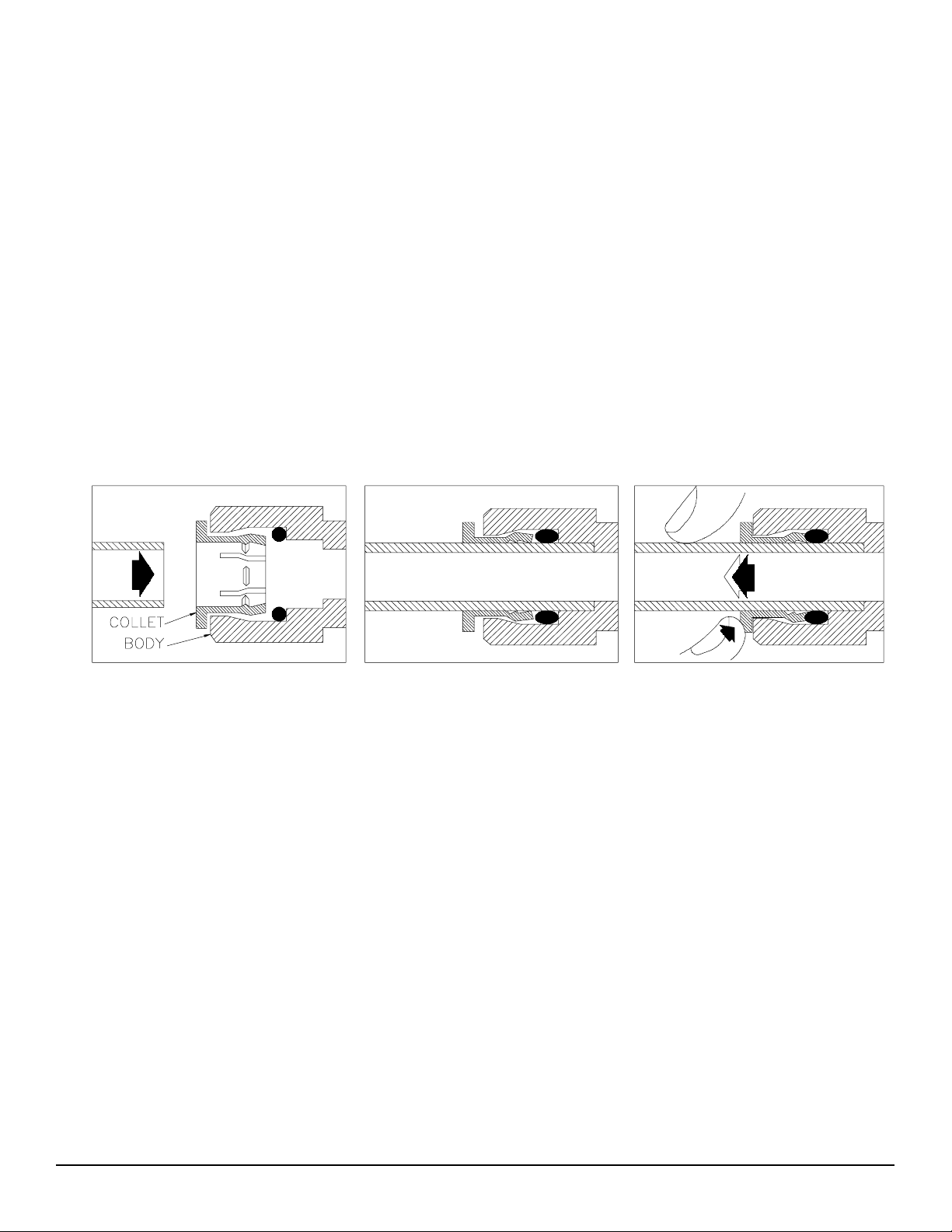
QUICK-CONNECT FITTINGS
Fittings consist of two parts: a Body and a colored Collet.
The Collet color corresponds to the tubing color to be
used at that connection (See Figure 2A.).
1. To install a tube, push it through Collet until it seats
firmly at bottom of fitting (Figures 2.A. and 2.B.).
2. To remove a tube, push and hold the Collet against
the Body while pulling the tube out (Figure 2.C.).
NOTE: Systems are shipped with a plug in each fitting
(prevents leakage of sanitizing fluid). Remove a
plug in the same manner as a tube.
A. Push tube through Collet into Body B. Tube must seat firmly at bottom of fitting C. Push Collet against Body to release tube
Figure 2 How to Use Quick-Connect Fittings
1
Page 6
SADDLE-TAPPING VALVE INSTALLATION ON COPPER TUBE
CAUTION: This saddle-tapping valve is not designed for installation on flex line tubing.
NOTE: State and local plumbing codes may prohibit use of saddle-tapping valves.
1. CAUTION: If no shut off valve is installed under
sink, close main water valve during this Installation.
4. Connect source water feed tubing to valve body
using compression fitting.
Locate shut off valves on water lines under sink. To
identify hot supply pipe and cold supply pipe, turn
both faucets on and let water run. As water flows, hot
water pipe becomes noticeably warmer.
2. CAUTION: Do not install feed water assembly on hot
water line.
Turn off cold water supply by closing shut off valve.
Drain line by opening sink faucet. Some mixing type
faucets may require hot water supply be shut off as
well.
NOTE: All instructions refer to components shown in
Figure 3 unless otherwise noted.
3. CAUTION: Do not turn valve handle before or while
installing saddle-tapping valve. Make sure piercing
lance does not protrude beyond rubber gasket before
installing valve.
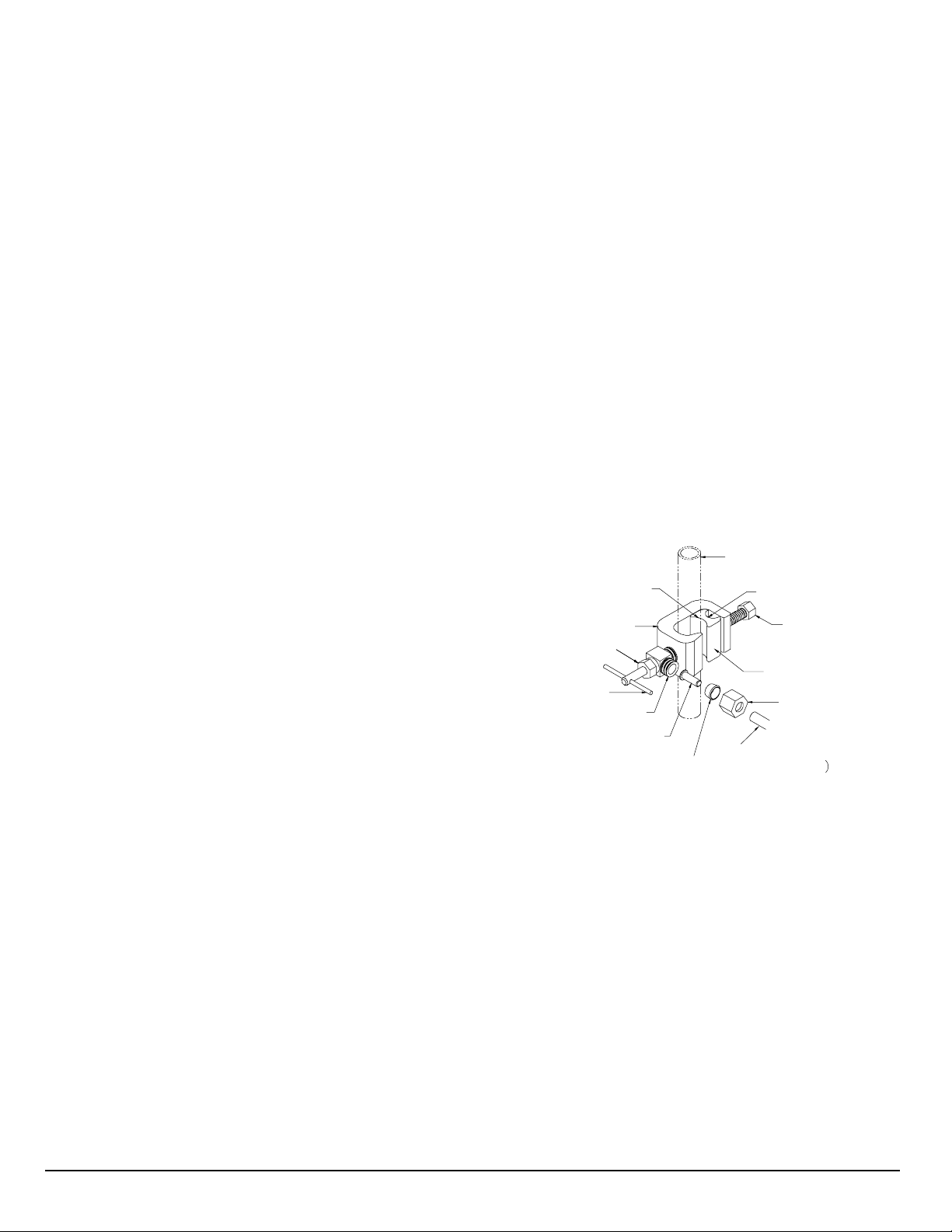
Assemble saddle-tapping valve assembly on tube.
a. Hold back plate against tube.
• 3/8" copper tubing use back plate smaller
radius.
• 1/2" copper tubing, use back plate larger
radius
b. Hold valve saddle against tubing in a position
directly opposite back plate.
c. Tighten screw enough so valve saddle and back
plate are held securely against tube.
d. Rotate assembly so tubing connection is aligned
toward 104 Series Module feed port.
e. Tighten screw firmly. Do not crush tube.
a. Slide nut and sleeve onto tubing (in that order).
b. Install insert into plastic tubing.
c. Install tube with insert and sleeve into valve body.
d. Thread compression nut onto valve body, tighten.
5. Turn saddle-tapping valve handle clockwise until it is
firmly seated and piercing lance is fully extended.
6. CAUTION: Supply line is pierced and valve is closed.
Do not open valve until system is activated (Page 10).
Turn on cold water supply. Check saddle-tapping
valve installation for leaks. Allow water to run from
faucet for a few minutes to clear any debris in the line
caused by installation.
NOTE: If flow from sink faucet is reduced, clean
faucet aerator.
EXISTING 1/2"
COPPER TUBING
HOUSEHOLD
LARGER RADIUS
VALVE SADDLE
STEM SEAL NUT
VALVE HANDLE
VALVE BODY
INSERT
SLEEVE
COLD WATER LINE
SMALLER RADIUS
TIGHTENING
SCREW
REVERSIBLE
BACK PLATE
COMPRESSION
NUT
TUBING TO MODULE
(1/4" WHITE TU BING
Figure 3: Saddle-Tapping Valve Assembly
P/N 34900013 installed on
1/2” Copper Tubing
ADDITIONAL POINT OF USE CONNECTION
NOTE: Icemakers typically use 1/4" tubing as feed line. Use a reducing union (P/N 33503407) for this connection.
NOTE: Reduce the 3/8” Line to 1/4” as close as possible to the additional point-of use device to minimize flow loss.
1. To connect an additional point of use (icemaker, extra
faucet in wet bar and/or another use for treated water),
place a "tee" connector (P/N 33503703) in 3/8" blue
line between faucet and back of 104 Series Module.
2. Connect "tee" to point-of-use with 3/8" blue tubing
(P/N 60602001). Connect tubing to point-of-use.
Connector requirements are based on type of
delivery device i.e., a typical icemaker uses
3/8" x 1/4" reducing device (P/N 33503407).
2
Page 7

INLET ADAPTER VALVE INSTALLATION
NOTE: This assembly is offered as an optional installation method. Make sure it is approved for use under
State and local plumbing codes before ordering kit (P/N 42500004).
NOTE: Use this assembly on U.S.N.P.T.* pipe thread fittings only.
1. CAUTION: If no shut off valve is installed under sink,
close main water valve during this installation.
Locate shut off valves on water lines under sink. To
identify hot supply pipe and cold supply pipe, turn both
faucets on and let water run. As water flows, hot water
pipe becomes noticeably warmer.
2. CAUTION: do not install feed water assembly on hot
water line.
Turn off cold water supply by closing shut off valve.
Drain line by opening sink faucet. Some mixing type
faucets may also require turning off hot water supply.
NOTE: All item callouts refer to Figure 4 unless noted
otherwise.
3. CAUTION: Place container or towel below shut-off
valve to catch any water remaining in pipe.
Disconnect cold water supply line to sink at inlet valve
end of line.
4. Insert rubber washer (Item 1) into inlet adapter
(Item 2) and install adapter onto supply valve.
Align outlet hole (in side of adapter) toward location
of RO Module.
5. Replace existing rubber grommet on cold water
supply line with grommet supplied in kit (Item 3).
6. CAUTION: Use thread-sealing tape (P/N 35700002)
on male threaded connections in Steps 4, 6, 7, and 8.
Attach cold water supply line to inlet adapter.
7. Install ball valve (Item 4) into inlet adapter.
8. Install male connector (Item 5) into inlet ball valve.
9. Install ¼” white tubing (Item 6) from male connector to
filtration module inlet elbow (Item 7 on Page 9,
Figure 10).
10. Close inlet valve by turning handle so it is at a right
angle (90º) to valve body.
11. CAUTION: Do not open valve until system is
activated (Page 10).
Turn on cold water supply. Check installation for leaks.
Allow water to run from faucet for a few minutes to
clear any debris in the supply line caused
by this installation.
NOTE: If flow from faucet is reduced, clean faucet
aerator.
Item Description Part No.
COLD WATER LINE
TO SINK
Inlet Assembly
#6
#3
1 Rubber Washer 33400002
2 Inlet Adapter 1/2" x 1/2" x 1/8" 33201001
#2
3 Rubber Grommet 33400003
#5
#4
EXISTING COLD WATER
SUPPLY VALVE
#1
* United States National Pipe Thread
Figure 4 Inlet Adapter Assembly P/N 42500004 Installation and Parts Breakdown
4 Inlet Ball Valve 1/8" 34900002
5 Male Connector 1/4" x 1/8" NPT* 33503301
Component of Installation Kit
6 Tubing, 1/4" White 20300014
- 3 -
Page 8

PRODUCT WATER FAUCET SITE PREPARATION
Refer to Faucet Installation Instructions (Pages 5 & 7) for site location and mounting hole specifications.
Primary considerations for site selection are convenience of use and an open area under sink.
Always check underside of selected location for obstructions.
PORCELAIN/ENAMEL OVER STEEL
OR CAST IRON SINKS
1. CAUTION: A heavy duty, variable speed drill motor
with a spring-loaded porcelain drill set (Figure 5.B.) is
strongly recommended for this procedure.
CAUTION: The plastic sleeve supplied on pilot drill
(Figure 5.A) is to be positioned on drill bit against drill
chuck. This prevents chuck from contacting
porcelain after pilot hole has been completed.
Using carbide tipped bit with plastic sleeve (Figure
5.A.), drill pilot hole completely through porcelain and
metal underneath.
NOTE: Practice on discarded sinks to become
familiar with operation of porcelain cutter kit.
2. CAUTION: Avoid high motor R.P.M. during initial
penetration of porcelain, as high drill speed will cause
excessive chipping.
STAINLESS STEEL SINK
1. Use a center punch to make a small indentation to
mark center of desired location.
2. Drill a pilot hole with a 1/8" metal drill bit, then enlarge
hole with a 3/8" metal drill bit.
3. Complete hole size by using a 1 1/4" chassis punch
available from your dealer (P/N 36201006).
4. Installation hole is ready, install faucet.
A. PILOT DRILL
Place spring-loaded porcelain saw (Figure 5.B.) into
drill chuck. Make sure pilot guide is inserted tightly.
Insert pilot guide into pilot hole. Push down gently on
drill motor to apply light pressure to porcelain surface.
Start drill motor turning as slowly as possible.
After initial cut has started, motor speed may be
gradually increased. The cut may require three to four
minutes to complete. Going faster could result in
excessive chipping. Be sure a complete ring has been
cut through porcelain to material underneath.
3. Place finish hole saw (Figure 5.C.) into drill chuck.
Make sure pilot guide is inserted tightly. Insert pilot
guide into pilot hole. Begin cut using a slow speed
and light pressure until porcelain (inside ring cut in
Step 2) has been penetrated to material underneath.
4. Remove saw from hole and clean all debris from
porcelain surface. Re-insert saw into hole and cut
through remaining material.
5. Installation hole is ready, install faucet.
TILE COUNTER TOP
1. Follow procedures detailed in section labeled
"Porcelain/Enamel Over Steel" (substitute "tile" for
"Porcelain" in instructions).
B. SPRING LOADED PORCELAIN SAW
C. FINISH HOLE SAW
Figure 5 Porcelain Cutter Kit P/N 36201003
- 4 -
Page 9

PRODUCT WATER FAUCET INSTALLATION - STAINLESS STEEL OR CHROME FAUCET
Install faucet on flat surface at least 2" in diameter. Unused 1 1/4" hole is ideal.
Steps unique to a specific configuration are so noted. All other steps are common to either configuration.
New Faucet Installation
Refer to Faucet Site Preparation, Page 4.
Replacement Faucet Installation
Verify size of existing hole is 1 1/4".
NOTE: Item callouts refer to Page 6, Figure 7 unless
noted otherwise. Part numbers for each callout
are specified according to faucet type:
Chrome-Plated Faucets (brass faucet nipple):
Table A.
Stainless Steel Faucets (copper faucet nipple):
Tables B and C.
1. Push Button Smartap
: Verify faucet body, rubber
body washer, metal base washer, and rubber base
washer are in place above sink (Items 1, 12, 2 and 8).
Optional Faucet Smartap
: Verify faucet body,
rubber body washer, metal base washer, light bar
base washer, light bar assembly, and washboard
gasket are in place above sink (Items 1, 12, 2, 9, 10,
and 11).
2. Push Button Smartap
Optional Faucet Smartap
: Place faucet over hole.
: Insert monitor cord into
mounting hole and place faucet over hole.
3. CAUTION: Do not pinch, kink, or otherwise deform
monitor cord. Align cord with cutout in plastic spacer.
Push Button Smartap
: Install locating washer,
faucet washer, and nut on faucet nipple below sink
and snug them up (Items 7A, 6, and 5). Be sure to
align faucet properly before tightening. Do not over
tighten.
Optional Faucet Smartap
: Install slotted washer,
spacer, faucet washer, and nut on faucet nipple below
sink and snug them up (Items 7, 3, 6, and 5). Be sure
to align faucet properly before tightening. Do not over
tighten.
4. Install faucet connector (Item 4, packaged with faucet)
onto faucet nipple. Do not over tighten.
5. Install 3/8” blue tube into faucet connector.
6. CAUTION: Blue 3/8" tube connecting module to the
faucet must run with no sharp bends or loops (See
Page II, Figure 1).
Connect 3/8" blue tube to 3/8" swivel elbow located on
the rear of module.
7. Optional Faucet Smartap
: Connect monitor cord
to telephone-style connector located on manifold
cover (Figure 6).
8. The basic installation is complete and system is
ready for activation (see Page 10).
FROM
SMARTAP SERVICE
INDICATOR LIGHT
Figure 6 Connecting Monitor cord to Manifold.
- 5 -
Page 10

12
®
®
SINK OR COUNTER MATERIAL
7
A
(PUSH BUTTON
SMARTAP)
1
2
(FAUCET SMARTAP )
3
MONITOR CONNECTOR
6
5
FAUCET NIPPLE
(PUSHBUTTON SMARTAP )
8
(FAUCET SMARTAP )
9
10
11
7
(FAUCET
SMARTAP )
4
DRINKING WATER LINE
FROM POST-FILTER
TO FAUCE T(3/8" BLUE TUBING)
A Chrome Plated Metal Faucet Two Options B + C Stainless Steel Faucet with Light Bar 11702002
Item Description Part No. Item Description Part No.
Stainless Steel Faucet 40301003
A
Chrome Plated Metal Faucet 40301102
(Faucet not available in California)
A
Chrome Plated Metal Faucet 40301002
(EPA and California Proposition 65 Compliant)
1
Body, Faucet - Chrome
2
Washer, Faucet Base - Chrome
4
Connector, Faucet - 3/8" x 7/16"
5
Nut, Faucet
6
Washer, Faucet
Washer, Locating (Replaces Items 3 and 7, Shape may vary)
7A
Washer, Rubber - Faucet Base
8
Washer, Rubber - Body Base
12
B
Body, Faucet - Stainless Steel
1
Washer, Faucet Base - Stainless Steel
2
Connector, Faucet - 3/8" x 7/16"
4
Nut, Faucet
5
Washer, Faucet
6
Washer, Locating (Replaces Items 3 and 7)
7A
Washer, Rubber - Faucet Base
8
Washer, Rubber - Body Base
12
C Light Bar Assembly 2LED 41200002
3
Spacer, Plastic (with cutout)
7
Washer, Slotted
9
Washer, Faucet Base Lt Bar (replaces Item 8)
10
Light Bar - 2 Indicator Lights
11
Gasket, Washboard F/M
Figure 7 Parts Breakdown, Metal Non-Air Gap Product Water Faucet Assemblies, Chrome, or Stainless Steel
- 6 -
Page 11

PRODUCT WATER FAUCET INSTALLATION - POLYMER FAUCET
Install on flat surface at least 2 7/16" in diameter. Unused 1 1/4"- 1 7/16" opening is ideal.
New Faucet Installation
Refer to Faucet Site Preparation, Page 4.
Replacement Faucet Installation
Verify size of existing hole. If hole measures 1 7/16",
Faucet may be installed without changes. If hole measures
1 1/4", remove two locator tabs (Figure 8) prior to
installation by breaking them off at faucet base.
FAUCET BODY
TAB
Figure 8 Faucet Locator Tabs and Air Gap.
1. Remove mounting nut and "U" bracket from faucet.
2. Install 3/8" blue tube into blue collet in faucet base.
3. CAUTION: Do not pinch, kink, pull, or otherwise
deform monitor cord.
Hydrotap
Logo (without Light Bar): Insert blue
tube into mounting hole and place faucet over hole.
Align faucet body with narrow face forward.
Smartap
Logo (with Light Bar): Insert blue tube
and monitor cord into mounting hole and place faucet
over hole. Align faucet body with light bar forward.
4. Install "U" bracket and mounting nut below sink.
Tighten mounting nut by hand
so that faucet does not
move. Do not over tighten.
NOTE: Faucet is packaged for right-hand operation. For
left-hand operation, realign handle by completing Step 5.
NOTE: Item callouts in Step 5 refer to Page 8,
Figure 9.
5. Align faucet knob for left-hand operation.
a. Rotate knob to rear of faucet (closed position).
b. Remove knob cover (Item 1) using a thin, flat tool
to pry cover from knob.
c. Remove knob attachment screw (Item 2) using a
Phillips-head screwdriver.
d. Remove knob (Item 3) by pulling it (by hand)
straight up. Rotate handle counterclockwise 90º,
and re-install knob.
e. Install knob attachment screw. Tighten screw
until free movement (i.e., rocking) is eliminated.
f. Snap knob cover into place.
6. Install spout into faucet body. Lubricate “O” ring with
FDA approved Silicone Lubricant. Align spout with
faucet outlet, gently push spout to bottom of outlet.
7. Light Bar: Connect monitor cord to module. Insert
cord into a telephone-style connector located on
module cover (See Page 5, Figure 6).
8. CAUTION: Blue 3/8" tube connecting module to the
product water faucet must run with no sharp bends or
loops (See Page II, Figure 1).
Connect 3/8" blue tube to swivel elbow located on
rear of module.
9. The basic installation is complete and system is ready
for activation (see Page 10).
CLEAN FAUCET SURFACE USING DISHWASHING DETERGENT ONLY. DO NOT USE ABRASIVES OR SOLVENTS.
- 7 -
Page 12

Item Description Part No. Item Description Part No.
1
2
3
4
5
Cover, Knob - Chrome - Plated
Screw, Knob
Knob, Faucet - Black
Spout, Faucet Polished
Tip, Spout - Black
35800502
32701021
20800904
35801308
20801504
6
7
8
9
10
“O” ring, Spout
Body Assembly - Chrome Plated Plain
Body Assembly - Chrome Plated 3 LED
Gasket, Sink
“O” ring, Tube Spacer/Stop
Collet 3/8” Blue
Figure 9 Parts Breakdown, Non-Air Gap Product Water Faucet, Polymer Chrome-Plated - Black, Hydrotap
11411100 and Smartap
Logo (with Light Bar) P/N 11402320
- 8 -
34201004
20819001
34201019
33502005
Logo P/N
--------
--------
Page 13

Push Button Smartap® Monitor
Module Cover and Flow Switch Assembly
®
Faucet Smartap
Monitor
Module Cover and Flow Switch Assembly
Item Description Part No.
1
Cover, 4-vessel Manifold - No Monitor
2
Bracket, Mounting
3
Screw, Mounting Bracket
4
Screw, Retaining Plate
5
Cover Assy, Inlet Valve w/”O” Rings
6
“O” Ring, Inlet Valve Cover
7
Elbow, 1/4" Stem w/white collet
8
Elbow, 3/8" Stem w/blue collet
9
Control Assembly, Flow 0.5 GPM
10*
Manifold 4 vessel, 104 Series No Monitor
10A**
Manifold 4 vessel, 104 Series with Monitor
11
Housing, Filter
12
“O” Ring, Filter Housing
13
Cartridge, Carbon VOC Reduction
14
Cartridge, Carbon Lead Reduction
15
Tube, Parallel Cross-over
16
Tube Stop
17
Plug Assy, Port Retainer w/O-Rings
18
Plug, Switch Housing
19
"O" Ring, Switch Housing Plug
20
"O" Ring, Cartridge
Optional Faucet Smartap
Cover, 4-vessel Manifold - Faucet Monitor
21
Switch Assembly, Flow Meter
22
Monitor, Flow - Faucet Smartap
23
Battery, Alkaline 9 volt
24
Optional Push Button Smartap
Cover, 4-vessel Manifold – Push Button
25
Switch Assembly, Flow Meter
26
Monitor, Flow, Push Button Smartap
23
Battery, Alkaline 9 volt
27
Push Button, Monitor
25
Guard, Push Button
28
®
Flow Monitor
®
®
Monitor
®
43014055
21100001
32701006
32701038
42200002
34201024
33503502
33503503
40600009
41300042
41300033
20500023
34201026
41400011
41400010
42200001
20500094
42200008
20500026
34201021
34201010
43014057
40200043
40200102
31300001
43014056
40200043
40200103
31300001
20500080
20500050
*Includes Items 4, 5, 6, 7, 8, 9, 15, 16,
17, 18 and 19.
**Includes Items 4, 5, 6, 7, 8, 9, 15, 16, 17,
and 22.
Figure 10 Parts Breakdown, 104 Series Four Vessel Manifold Module
- 9 -
Page 14

ACTIVATING THE SYSTEM
CAUTION: Make sure all water supply lines, drain lines, and fittings are secure and free from leakage.
1. Open saddle-tapping valve. Check for leakage.
2. Open product water faucet and let water flow to drain
for at least 10 minutes. This will expel the air from the
system.
3. Close product water faucet. In 5 minutes, check the
connections for leaks and correct if necessary
Icemaker/Extra point of use
: Check connections on
these supply lines for leaks.
NOTE: Item Callouts refer to Page 9, Figure 10 unless
noted otherwise.
Systems with Smartap Water Flow Monitor complete
Steps 4 through 7.
4. CAUTION: Wiring within module cover connects
monitor components. If wires, circuit board, or
connections are damaged and/or wetted, monitor will
not function.
Loosen mounting bracket screws (Item 3). Gently pull
module cover (Item 1) up and away from the manifold
body.
5. CAUTION: Verify battery connector alignment before
making connection (Figure 11).
Connect battery (Item 24) by pressing clip onto battery
terminals.
6. Replace module cover and tighten screws.
7. Test battery connection by activating monitor. Open
product water faucet or press push button, whichever
is applicable. If an indicator light illuminates,
connection is good.
NOTE: Close faucet immediately after light
illuminates. Test is to confirm battery connection, not
water quality.
Icemaker
: Let tray/bin fill with ice cubes. Discard all
ice cubes. This flushes sanitizing solution from lines
to icemaker.
8. System is ready to use. Should there be any
aftertaste or odor to water or ice cubes, repeat
Steps 6 and 7.
MAINTENANCE - WARRANTY INFORMATION
Recommended Service Intervals Warranty
Replace filters as required based on Smartap® Water Flow Monitor indications
or every 6 to 12 months depending on feed water quality.
CRITICAL COMPONENTS
Non-Air Gap Metal Faucet Part Number Non-Air Gap Polymer Faucet
Chrome Plated Brass*
Chrome Plated Brass**
Stainless Steel
Stainless Steel with Light Bar
* Faucet not available in California
**EPA and California Proposition 65 Compliant
PARTS AND SERVICE ARE AVAILABLE THROUGH YOUR LOCAL WATER TREATMENT DEALER.
40301102
40301002
40301003
11702002
Black/Chrome
Polymer, Hydrotap
Polymer, Smartap
(with Light Bar)
Logo
®
Logo
System: 2 years limited
Part Number Carbon Cartridges Part Number
11411100
11402320
Lead Reduction (Black Cap)
VOC Reduction (White Cap)
Smartap
®
: 5 years
41400010
41400011
- 10 -
Page 15

HAVE ALL COMPONENTS ON HAND AND READY BEFORE BEGINNING PROCEDURE.
A CLEAN WORK AREA AND EQUIPMENT ARE ESSENTIAL TO PROPERLY CLEAN AND/OR SANITIZE THE SYSTEM.
(I.e., CLEAN HANDS, TOOLS, WORK SURFACE, AND CONTAINERS)
ROUTINE MAINTENANCE
RECOMMENDATIONS
SERVICE REQUIREMENTS
To insure the system operates at its optimum level,
certain routine maintenance must be performed.
Safety glasses
Rubber gloves, sanitary
Wash Cloth, Clean and Lint-free
REPLACEMENT FILTER SETS “O” RINGS
P/N 41400011 Carbon Filter, VOC Reduction (White Cap) - 1 each
P/N 41400010 Carbon Filter, Lead Reduction (Black Cap) - 3 each
Frequency of maintenance performance will depend on
feed water quality and level of system usage.
EQUIPMENT NEEDED
Household bleach - Unscented Only
(5 1/4% sodium hypochlorite)
Liquid dish soap
CLEANING, SANITIZING, AND CARTRIDGE REPLACEMENT PROCEDURE
1. Mix a mild cleaning solution of dish soap and clean
potable water in the plastic bowl.
2. Shut feed water supply valve and open product water
faucet to relieve system pressure.
3. CAUTION: Do not attempt to remove filter housings
until water flow stops. This reduces pressure inside
the system so housings may be removed safely.
CAUTION: Additional point-of-use devices (i.e.,
icemakers) may use filters along their supply line.
Remove any filter or treatment device installed
between module and delivery device before
proceeding.
Remove each filter housing by turning it counter clockwise. Remove each filter cartridge as its housing
is removed. Discard filters.
Icemaker
freezer container for storage until procedure is done.
4. CAUTION: Use sanitary rubber gloves for this
procedure to avoid contaminating sanitizing solution or
filters. Wear gloves whenever cleaning/ sanitizing
system components or handling new filter cartridges.
Remove filter housing "O" rings and wash them with
cleaning solution. Rinse them well with clean potable
water. Inspect the "O" rings for damage (i.e., nicks or
scratches). Replace damaged "O" rings.
: Transfer ice cubes from bin/tray to clean
CLEAN: Each time filters are replaced
SANITIZE: At least once every 12 months.
Plastic bucket, Plastic bowl
“O” Ring Lube FDA Approved
(P/N 30300026)
P/N 34201010 Filter Cartridge
P/N 34201026 Filter Housing
5. CAUTION: Do not get the Smartap
electronics, wiring, or connectors wet.
Clean filter housings and manifold ports, inside and
outside with washcloth and cleaning solution. Do not
use abrasive materials.
6. Rinse housings/manifold with clean potable water.
7. Inspect manifold and filter housing "O" ring groove
area for damage (i.e., nicks or scratches). Replace
damaged components.
8. Place a small amount of "O" ring lubricant over the
surface of the filter housing "O" ring. Install the "O" ring
into the filter housing groove.
TO SANITIZE SYSTEM: Complete Steps 9-29.
TO INSTALL FILTERS: Complete Steps 17-29.
WARNING: WEAR SAFETY GLASSES WHILE
PERFORMING THIS PROCEDURE.
WARNING: READ THE "WARNINGS" ON THE BLEACH
CONTAINER BEFORE USING.
WARNING: HANDLE SANITIZING SOLUTION
CAREFULLY. AVOID CONTACT WITH UNPROTECTED
AREAS.
®
Flow Monitor
- 11 -
Page 16

CLEANING, SANITIZING, AND CARTRIDGE REPLACEMENT
9. CAUTION: Excessive concentrations of bleach will
damage plastic and rubber components. Rinse all
parts that contact bleach thoroughly with clean potable
water.
Mix sanitizing solution of 1.5 ml (1/3 teaspoon) of
household bleach and 3.8 L (1 gallon) of clean,
potable water in the bucket. Mix the solution well.
10. CAUTION: Tighten filter housings by hand only.
Do not use tools as they will over-tighten and damage
housings. Take care not to cut or pinch “O” rings.
Add 236 ml (one cup or 8 oz.) of sanitizing solution to
each of the filter housings and install them onto the
manifold (do not install filters at this time). Tighten
each filter housing by hand only.
11. Slowly open the feed water supply valve.
12. Open product water faucet. Keep it open for 5
seconds after water starts coming out.
13. Close the product water faucet.
14. Wait 30 minutes, open product water faucet and let
water flow 5 minutes.
15. After 5 minutes, close feed water supply valve and
allow water to flow until system pressure is relieved.
16. CAUTION: Do not attempt to remove filter housings
until water flow stops. This reduces pressure inside
the system so housings may be removed safely.
Remove the filter housings and dispose of the water.
Rinse housings and manifold ports thoroughly with
clean potable water.
17. CAUTION: Do not remove protective plastic bag from
filters until so instructed.
Open the top of the bag only enough to expose
the top cap and "O" rings. Place a small amount of
“O” ring lubricant on surface of each “O” ring.
Install the filter cartridges. Hold cartridge by its
protective plastic bag and insert the cartridge into the
manifold turning it 1/2 turn as it enters the port (See
Page II, Figure 1 for location of each cartridge).
Slide bag from cartridge and discard it.
CAUTION: Tighten filter housings by hand only.
Do not use tools as they will over-tighten and damage
housings. Take care not to cut or pinch “O” rings.
NO WATER FLOW MONITOR:
Complete Steps 26 - 29
OPTIONAL SMARTAP
®
WATER FLOW MONITOR:
Complete Steps 18 – 29
Smartap
®
Flow Monitor Operation Requirements:
Monitor must be reset to zero each time system is serviced
and cartridges replaced. If monitor is not reset, there is no
way to determine when filters were changed or if the
system is still operating within specifications.
Monitor is reset when the battery (Item 24) is disconnected
from the clip. Failure to replace battery may result in
yellow light when system is reconnected.
Installing a new battery when filter cartridges are replaced
ensures an accurate indication of system performance and
a continuing supply of high quality drinking water.
18. CAUTION: The wiring within the module cover
connects the monitor components. If wires, circuit
board, or connections are damaged and/or wetted,
monitor will not function.
Loosen three mounting bracket screws. Gently pull
module cover up and away from module body.
19. Disconnect the battery. The connection to the battery
is a snap type connector (See Figure 11).
20. Remove the battery by sliding it out of its holder.
21. Replace the battery with a new alkaline 9-volt
transistor battery (P/N 31300001).
22. Carefully slide the battery into its holder.
23. CAUTION: Verify battery connector alignment before
making connection (Figure 11).
Reconnect the battery by pressing the clip onto the
battery terminals.
24. Replace the module cover and tighten screws.
25. Turn feed water valve slowly to the open position.
26. Test battery connection by activating the monitor.
Pressing the test button or open the product water
faucet. If an indicator light illuminates, connection
is good.
Replace each filter housing as each cartridge is
installed.
NOTE: Close faucet after light illuminates. Test
confirms connection, not system status.
- 12 -
Page 17

CLEANING, SANITIZING, AND CARTRIDGE REPLACEMENT
27. Open product water (and extra point-of-use) faucet.
Let water flow until all air has been expelled from
system.
28. Close product water (and extra point-of-use) faucet.
In 5 minutes, check the connections for leaks and
correct if necessary.
Icemaker
: Let the tray/bin fill with ice cubes. Discard
all ice cubes to the drain. This flushes sanitizing
solution from the lines to the icemaker.
29. Open product water (and extra point-of-use) faucet.
Let the water flow for 10 minutes. This will expel any
remaining air from the system.
30. System is ready to use. Should there be any
aftertaste or odor to the water or ice cubes,
repeat Step 29.
Figure 11 Smartap
®
Battery Connection
TROUBLE SHOOTING GUIDE
104 SERIES ADVANCED MULTI-STAGE WATER TREATMENT SYSTEM
Symptom Probable Cause Solution
No water. Water supply is turned OFF. Turn water ON.
Not enough water. Water supply is blocked.
Water has an offensive taste and/or odor. Filters depleted. Replace filters, clean and sanitize system.
Leak at fitting. Tubing not pushed completely into fitting.
Leak at filter housing. "O" Ring has not seated.
Leak at saddle tapping valve.
Clogged filter cartridges are restricting water flow.
Defective tube.
Worn or damaged "O" Ring.
"O" Ring has nick or scratches.
Loose clamp.
Tubing deformed.
Clear restriction, rotate valve handle on tap
water feed valve.
Replace filter cartridges.
Push tube into fitting past "O" Ring seal.
Cut damaged area off of tube or replace tube.
(refer to Page 1, Figure 2)
Replace "O" Ring*.
Lube and Reseat "O" Ring*.
Replace "O" Ring *.
Tighten clamp screws, do not crush source
water tubing.
Cut damaged area from tube or replace tube and
sleeve.
* Always check there is adequate lubricant (P/N 30300026) on "O" Rings before installation.
OPTIONAL SMARTAP® WATER FLOW MONITOR
Symptom Probable Cause Solution
Yellow Service Light. Filters depleted.
No Lights. Light assembly is not connected. Plug connector into phone jack.
CAUTION: Change the battery only when changing the filters as removal and replacement of the battery resets the Aquafier® monitor.
CAUTION: Change the battery each time the filters are changed. If battery is not replaced, user/technician cannot determine system status within cycle.
Table 3 System Troubleshooting Indicators, Common Solutions, and Correction Procedures
Battery not replaced when filters changed.
- 13 -
Replace filters.
Replace battery.
Page 18

INSTALLATION AND SERVICE RECORD
DATE INSTALLED SYSTEM: SERVICE FLOW 0.5 GPM
DATE SERVICED SERVICED BY COMPANY
SERVICE PERFORMED
FILTERS REPLACED
COMMENTS
DATE SERVICED SERVICED BY COMPANY
SERVICE PERFORMED
FILTERS REPLACED
COMMENTS
DATE SERVICED SERVICED BY COMPANY
CLEANING ONLY CLEANING & SANITIZING REPAIR
CARBON Pb1 LEAD CARBON 5s VOC's
CLEANING ONLY CLEANING & SANITIZING REPAIR
CARBON Pb1 LEAD CARBON 5s VOC's
SERVICE PERFORMED
FILTERS REPLACED
COMMENTS
DATE SERVICED SERVICED BY COMPANY
SERVICE PERFORMED
FILTERS REPLACED
COMMENTS
CLEANING ONLY CLEANING & SANITIZING REPAIR
CARBON Pb1 LEAD CARBON 5s VOC's
CLEANING ONLY CLEANING & SANITIZING REPAIR
CARBON Pb1 LEAD CARBON 5s VOC's
- 14 -
Page 19

INSTALLATION AND SERVICE RECORD
DATE INSTALLED SYSTEM: SERVICE FLOW 0.5 GPM
DATE SERVICED SERVICED BY COMPANY
SERVICE PERFORMED
FILTERS REPLACED
COMMENTS
DATE SERVICED SERVICED BY COMPANY
SERVICE PERFORMED
FILTERS REPLACED
COMMENTS
DATE SERVICED SERVICED BY COMPANY
CLEANING ONLY CLEANING & SANITIZING REPAIR
CARBON Pb1 LEAD CARBON 5s VOC's
CLEANING ONLY CLEANING & SANITIZING REPAIR
CARBON Pb1 LEAD CARBON 5s VOC's
SERVICE PERFORMED
FILTERS REPLACED
COMMENTS
DATE SERVICED SERVICED BY COMPANY
SERVICE PERFORMED
FILTERS REPLACED
COMMENTS
CLEANING ONLY CLEANING & SANITIZING REPAIR
CARBON Pb1 LEAD CARBON 5s VOC's
CLEANING ONLY CLEANING & SANITIZING REPAIR
CARBON Pb1 LEAD CARBON 5s VOC's
- 15 -
Page 20

LIMITED WARRANTY
Subject to the conditions and limitations described below, WaterGroup warrants its Model 104 Series Advanced MultiStage Water Treatment Systems (excluding cartridge filters and battery), when installed in accordance with our
specifications, to be free from defects in materials and workmanship under normal use within the operating
specifications for a periods of two (2) years from the date of purchase. WaterGroup also warrants the Smartap
Quality Monitor to be free from defects in materials and workmanship under normal use within the operating
specifications for a periods of five (5) years from the date of purchase. This warranty shall apply only to the original enduser of the drinking water system.
Other than the cartridge filters and battery, any part found defective within the terms of this warranty will be repaired or
replaced. If any part is found defective, WaterGroup also reserves the right to replace the drinking water appliance with
a comparable drinking water system of equal or greater quality. You pay only freight for repaired or replaced parts from
our factory and local dealer charges, including but not limited to labor charges, travel and transportation expenses and
handling fees.
This warranty shall not apply to any part damaged by accident, fire, flood, freezing, Act of God, bacterial attack,
sediment, misuse, misapplication, neglect, alteration, installation, or operation contrary to our printed instructions, or by
the use of accessories or components which do not meet our specifications. If the drinking water system is altered by
anyone other than WaterGroup, the warranty shall be void.
ALL IMPLIED WARRANTIES, INCLUDING WITHOUT LIMITATION WARRANTIES OF MERCHANTABILITY AND
FITNESS FOR PARTICULAR PURPOSE, ARE LIMITED TO THE DURATION OF THE PERIOD SPECIFIED ABOVE
FOR THE PARTS DESCRIBED IN THIS LIMITED WARRANTY.
As a manufacturer, we do not know the characteristics of your water supply. The quality of water supplies may vary
seasonably or over a period of time. Your water usage may vary as well. Water characteristics can also change if the
drinking water appliance is moved to a new location. For these reasons, we assume no liability for the determination of
the proper equipment necessary to meet your requirements, and we do not authorize others to assume such obligation
for us. Further, we assume no liability and extend no warranties, express or implied, for the use of this product with a
non-potable water source or a water source which does not meet the conditions for use as described in this Owner’s
Guide.
WATERGROUP’S OBLIGATIONS UNDER THIS WARRANTY ARE LIMITED TO THE REPAIR OR REPLACEMENT OF
THE FAILED PARTS OF THE DRINKING WATER SYSTEM, AND WE ASSUME NO LIABILITY WHATSOEVER FOR
DIRECT, INDIRECT, INCIDENTAL, CONSEQUENTIAL, SPECIAL, GENERAL OR OTHER DAMAGES, WHETHER
FROM CORROSION OR OTHER CAUSES.
Some states do not allow limitations on how long an implied warranty lasts, so the above limitations may not apply to
you. Similarly, some states do not allow the exclusion of incidental or consequential damage, so the above limitation or
exclusion may not apply to you. This warranty gives you specific legal rights, and you may have other rights that vary
from state to state.
®
Water
WaterGroup Inc. WaterGroup Companies Inc.
193 Osborne Road
Fridley, MN
U.S.A. 55432
Tel. # - 763-571-9001 (USA)
Tel. # - 306-761-3247 (CANADA)
© Copyright 2005 WATERGROUP, INC.
Manufactured at 2375 Sanders Rd. Northbrook, IL 60062
9848 Glenoaks Boulevard
Sun Valley, CA
U.S.A. 91352
580 Park Street
Regina, SK
Canada, S4N 5A9
265 Industrial Road
P.O. Box 5000
Cambridge, ON
Canada N3H 5N3
For parts and service, contact:
Form OGAQ-07 01.06
Part No. 36101004
 Loading...