

Hydrotec HYDROION VAS 75-CS 1-A, HYDROION VAS 25-CS 1-B, HYDROION VAS 75-CS 1-B, HYDROION VAS 125-CS 1.5-A, HYDROION VAS 125-CS 1.5-B Operating And Maintenance Manual
...
Last change 10/2018 E-P | Subject to technical modifications
Operating and Maintenance Manual
®
HYDROION
Type: VAS – CS
Serial number: ____________________
HYDROTEC UK Ltd. Telephone 01494 796040
Hydrotec House
5 Manor Courtyard, Hughenden Avenue
High Wycombe, Bucks. HP13 5RE Fax 01494 796049
Web: www.hydrotec.co.uk
1/98

Last change 10/2018 E-P | Subject to technical modifications
Index
The individual chapters are listed in the survey below. More detailed information is shown in
the respective overlays.
Preface
Chapter I General information
Chapter II Transport and storage
Chapter III System description / Technical data
Chapter IV Assembly and installation
Chapter V Micro processor control
Chapter VI Start up / Taking out of service
Chapter VII Troubleshooting
Chapter VIII Monitoring and maintenance
Appendices 1 Installation schematic softener
Appendices 2 Calculation soft water capacity
Appendices 3 Calculation sodium content
Appendices 4 Start up and training record - Softener HYDRO ION®
Appendices 5 Log book
Appendices 6 Commissioning request
Appendices 7 PUROLITE - ION EXCHANGE RESIN - Safety data sheet
Imprint
2/98

Last change 10/2018 E-P | Subject to technical modifications
Preface
The HYDROION® Softener are constructed and manufactured with respect to and in consideration
of all current standards as well as further technical specifications, and corresponds to the latest
state-of-the-art technology, allowing for maximum safety under all operating conditions.
System safety in operation can only be assured if all necessary measures are taken beforehand. It
is part of the operator’s diligence to plan and monitor such measures and implement them with due
care.
The operating and maintenance manual includes important information for a save installation,
operation and commissioning. Please make yourself familiar with all details prior to start operation.
For any additional information or problems encountered in conjunction with operation, please
contact our Customer Service Department at the following address:
Hydrotec (UK) Ltd
Hydrotec House
5 Manor Courtyard, Hughenden Avenue
High Wycombe, Bucks HP13 5RE
Tel: 01494 796 040
Email: services@hydrotec.co.uk
3/98

Last change 10/2018 E-P | Subject to technical modifications
Index Chapter I – General information
Page
1. Documentation 5
2. Safety information 5
2.1 Operator’s duty of care 5
2.2 Appropriate use 6
2.3 Basic safety measures 6
Maintenance, repair and electric work 7
Start up after maintenance and repair work 7
Environmental regulations 7
2.4 Risk in the event of safety instructions being disregarded 8
2.5 Operational and ancillary materials 8
2.6 Used safety signs and instruction symbols 8
3. Warranty 9
4/98

Last change 10/2018 E-P | Subject to technical modifications
1. Documentation
The following information is included for the operator in the operation and maintenance manual:
• Safety information
• Information and instructions for assembly
start-up
operation
maintenance
troubleshooting
• Technical Data
The operation and maintenance manual together with all other technical information and documents
must always be kept readily accessible.
The O&M includes several chapters marked with roman numerals (see global index). The page
reference is shown right below on each page.
Information about the chapter contents see index on page 1 of each chapter.
For any additional information or problems encountered in conjunction with operation, please
contact our Customer Service Department at the following address:
Hydrotec (UK) Ltd.
Hydrotec House
5 Manor Courtyard, Hughenden Avenue
High Wycombe, Bucks HP13 5RE
Tel: 01494 796 040
Email: services@hydrotec.co.uk
2. Safety information
2.1 Operator’s duty of care
The system is constructed and manufactured with respect to and in consideration of all current
standards as well as further technical specifications, and corresponds to the latest state-of-the-art
technology, allowing for maximum safety under all operating conditions.
System safety in operation can only be assured if all necessary measures are taken beforehand. It
is part of the operator’s diligence to plan and monitor such measures and implement them with due
care.
The operator must ensure that:
- The system is used in accordance with the specified purpose
- The system is maintained in a serviceable condition, with the safety facilities being monitored
for correct function in regular intervals
- The operation and maintenance manual is always in a legible condition and available next
to the unit
- The operation, maintenance and repair work is carried out by qualified and authorised
personnel only
- All safety and warning information attached to the system must not be removed and must be
kept in a legible condition
5/98

Last change 10/2018 E-P | Subject to technical modifications
2.2 Appropriate use
The system is manufactured to the latest German technical safety standards employing the latest
state-of-the-art technology.
If incorrectly treated, not maintained properly at regular intervals or not used for the correct purpose
according to the specifications, the softener may incur risks and/or damage.
Operation of system shall be within the technical parameters and limit values in chapter III.
The softener unit is to be operated and maintained in good working order and according to the
specification it was designed for only.
Important! Any other use of the system, other than described, is deemed to be not in
accordance with the specification.
The manufacturer / supplier does not accept any liability resulting from the
improper use of the system. Such risks are borne by the operator alone.
All regulations and instructions in the operating and maintenance manual and
such regulations as are applicable locally must be strictly adhered to.
Any malfunctions must be corrected immediately.
2.3 Basic safety measures
Prior to starting the system it must be guaranteed that:
- No-one can suffer injury due to the system operation
- All safety facilities are in a perfectly serviceable condition
The system must be operated in perfect condition only. All faults must be notified to the person
responsible immediately after being noticed.
In order to avoid flooding of installation site, there is a drainage and / or leak control with alarm to be
provided locally.
6/98
Last change 10/2018 E-P | Subject to technical modifications
Maintenance and repair work
- All inspection and maintenance intervals specified in the operation and maintenance manual
must be adhered to
- Prior to any repair work, the system must be disconnected from mains
- Prior any repair and electrical work the system is to be disconnected from the piping system
(the system must be de-pressurised) and shall be protected from accidental restart
- Only suitable and correctly functioning load-supporting devices shall be used when replacing
heavy components or system elements
- Hose lines shall be replaced regularly (preventive maintenance) even if no damage is visible
- During work at the plant suitable and corresponding protective clothing shall be worn (e.g.
when handling with liquids such as acids and bases/alkalis)
Electrical work
- Prior to any work on electric components the system must be disconnected from the mains
- Electric equipment must be checked in regular intervals
- Any possible loose connections must be re-secured and damaged electric cabling replaced
immediately
- Casings of electric equipment and system components must never be cleaned with a water
hose (spray)
- Electric components must never be touched with wet hands
- Valid VDE regulations must be adhered to, especially the regulations for the required
potential equalisation
- EMC interferences must be avoided and if necessary a mains filter protection shall be
applied
- Cable connections shall always be kept as short as possible
- Sensor and low voltage cables shall never be laid parallel to current-carrying wires (230 V or
400 V).
Start-up after maintenance and repair work
- Check screw connections for tight fit
- Ensure that any components removed beforehand (e.g. tank lid, screen or filter) are installed
and restored to their correct operational position
- It is to be ensured that all material, tools and other appliances which were necessary for
maintenance and repair work are removed from the working area of the system
- Any liquid that has leaked is to be removed
- Ensure that all safety equipment is in a perfectly serviceable condition
Regulations in respect of environmental protection
When working on and with the system, all legal regulations in respect of waste minimisation and
proper disposal (if appropriate) must be observed and respected.
The water-endangering substances listed below in particular must not be allowed to contaminate the
soil or enter the drainage system during installation, maintenance and repair work:
7/98

Last change 10/2018 E-P | Subject to technical modifications
This icon indicates general information which must be observed during the
operation of water treatment systems.
This warning symbol indicates information which shall be observed for the
purpose of your own personal safety and to prevent any cause of damage to the
systems.
This warning symbol indicates work which shall only be carried out by qualified
electricians according to VDE regulations or by responsible institutions or
specialized companies.
This symbol indicates information which must be observed for handling of
environmentally hazardous and water-endangering substances.
This icon indicates information to be observed during any maintenance and repair
work and for maintenance intervals.
- Grease and lubrication oils
- Hydraulic oils
- Cooling agents
- Acids and alkalis (bases)
- Disinfection agents
- Cleaning materials containing solvents
Such substances must be stored, transported and collected in suitable tanks and disposed
of in accordance with the applicable regulations.
2.4 Risk in the event of safety instructions being disregarded
The consequences of disregarding safety instructions can be dangerous to the system, material and
personnel, and the loss of any warranty claims.
We shall accept no liability for possible water damage caused due to disregard of the safety
instructions.
2.5 Operational and ancillary materials
All materials shall be handled in accordance with the COSHH regulation (the Control of Substances
Hazardous to Health 2002). Material Safety Data Sheets are provided in the Appendices.
Safety datasheets
The operating media used:
- Highly acidic cation exchange resin
- Regeneration salt
are not considered to be hazardous substances in the meaning of the legal provisions.
2.6 Safety and warning symbols
8/98

Last change 10/2018 E-P | Subject to technical modifications
3. Warranty
The warranty period for the system is 12 months, calculated from either the date of commissioning
by Hydrotec (UK) Ltd. or 15 months from the date of supply in the event that commissioning is not
included with the supply agreement, whichever is the shorter. The plant must be operated and
maintained in accordance with Hydrotec (UK) Ltd’s requirements. It is recommended that a service
contract is taken out for the unit.
Claims under warranty will only be accepted in the meaning of our General Conditions of Sale and
Supply subject to the following conditions:
- The system is used and operated in accordance with information and instructions in the
operation and maintenance manual
- The system is treated properly
- Repair work is to be carried out exclusively by authorised specialists
- Original spare parts or parts recommended by Hydrotec (UK) Ltd. shall be used
exclusively
- No modifications are carried out on the system by users themselves
- The stipulated operation parameters (pressures, flow volume) are maintained and a
water temperature of 30°C is not exceeded
- Start-up of the system has been carried out by our service personnel
- That after installation and longer standstill periods a chemical disinfection has been
effected
- A yearly maintenance is carried out by our service personnel
Excluded from warranty claim are all parts subject to wear and tear such as:
- All moving parts, motors, seals, membranes, filter etc.
Warranty claims cannot be accepted in cases of:
- Operation and installation errors
- Faulty maintenance
- Deliberate damage or negligent handling
Any unauthorised modifications are not permitted for safety reasons. Original spare parts and
accessories are especially designed for the softener series HYDROION®.
Original spare parts shall be used exclusively!
Important information for any queries and spare parts orders:
- Softener type (model number)
- Serial number
- Date of manufacture
9/98

Last change 10/2018 E-P | Subject to technical modifications
Chapter II – Transport and storage
All system parts of the HYDROION® softener unit should be secured against jolting and
falling during transport and storage.
Appropriate means must be used in order to avoid and exclude any damage during transport.
The entire delivery must be checked for completeness and possible transport damage immediately
upon receipt at the warehouse / site.
Any transport damage must be notified to the supplier immediately.
Important!
Pressure tanks get damaged by shock load!
In order to protect the feet, the tanks shall be lifted for transport (not tilted!).
The system and resin must be protected from frost during transport and storage
(recommended temperature 5-40°C). Storage outside these conditions can damage and
destroy the resin and resin vessel.
Components, fittings and pipes shall never be used for fixing of conveyor belts or other
supporting means of transport!
Do not lift the system via the components, fittings or pipes!
If disregarded, system components can easily get damaged and break/crack!
Regeneration material
Common salt (sodium chloride) supplied in tablet form according to EN 973 (DIN19604) is to be
used as the regenerant. Typically the salt is supplied in 25 kg plastic sacks which must be stored in
clean and dry areas only.
Hydrotec (UK) Ltd. is not a salt supplier. Supply of salt is the responsibility of the operator.
10/98

Last change 10/2018 E-P | Subject to technical modifications
Index Chapter III – System description / Technical Data
Page
1. System description 12
1.1 General 12
1.2 Function 13
1.3 Water pressure 14
2. Technical Data 15
2.1 HYDRO ION® VAS – CS – A 15
2.2 HYDRO ION® VAS – CS – B 16
2.3 Installation schematic 17
2.4 Pressure loss 18
3. Scope of supply 19
3.1 Components 19
- Resin vessel 19
- Resin 20
- Control valve 20
- Micro processor control 21
- Water volume counter 21
- Brine tank 22
- Brine exhaust 22
- Brine lack sensor 22
- Chlorinator 23
- Measuring kit total (permanent) hardness 23
3.2 Accessories 24
- System separator 24
- Assembly mounting 24
- External blending 25
- Flexible hoses 25
- Regenerant 25
11/98
Last change 10/2018 E-P | Subject to technical modifications
fig.1
1. System description
1.1 General
Simplex softener HYDRO ION® VAS – CS
HYDROION® VAS softeners are designed and used to chemically transform hard water into soft
water. The treatment process is via the ‘ion-exchange’ method, whereby the hard water flows over
the resin media in the pressure vessel. The elements responsible for hardness, calcium and
magnesium ions present in the water are bound reversibly to the ion exchange resin and in return,
sodium ions are released into the water. The accumulation of calcium and magnesium ions
(hardness) on the resin is periodically removed by a regeneration process using sodium chloride
(common salt) solution or brine.
Plant type: HYDRO ION® VAS - CS – A / B (Salt saving mode)
Treatment normally for
- Drinking water application according to DIN 19636
- Preparation of cooling water according to VDI 3803
Softener designed as Simplex system.
12/98

Last change 10/2018 E-P | Subject to technical modifications
1.2 Function
System HYDRO ION® VAS exclusively suited to soften hard water having drinking water
characteristics.
That means the water must be clear, colourless, free from chlorine, iron, manganese and oil in order
to avoid a damage of the exchange material by blocking.
The feature of hard water is substantial for the efficiency of the ion exchange material and the
operation of the system.
The ambient temperature for the system must be free from frost and not exceed 40°C since
otherwise the ion exchange resin will be irreversibly damaged and/or the pressure resistance of
used materials is reduced.
The HYDRO ION® VAS water softener is controlled by a water meter.
The softening of the water is by means of the ion exchange resin in the pressure vessel. The
process of ion exchange is the exchange of the hard minerals (calcium and magnesium ions) with
sodium ions. Water treated in this manner is called softened water.
The ion-exchange resin becomes exhausted after a certain water volume has passed and at this
point it must be regeneration with sodium chloride (common salt).
Operation / regeneration of the softener in the different stages in accordance with the following
processes:
Operation = soft water production
The water to be treated passes through the iron exchange resin bed from top to bottom and goes to
service as soft water via a riser tube.
Backwash
Water passes through the ion exchange resin bed from bottom to top, to fluidise and aerate the bed.
The back wash is sent to drain.
Brining / slow rinse
Brine is drawn by means of an injector, diluted, and fed through the ion exchange resin from top to
bottom. Whilst the process is taking place, the calcium and magnesium ions attached to the resin
are exchanged for sodium ions, thus regenerating it. Effluent goes to drain.
13/98
Last change 10/2018 E-P | Subject to technical modifications
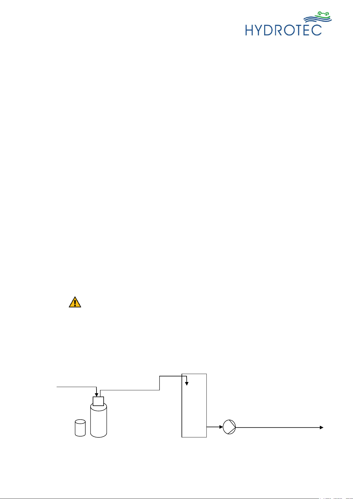
water
incoming
to the consumer
reservoir
pressure
booster
system
softener
fig.2
Fast rinse
Hard water flows from top to bottom through the ion exchange resin, driving out the excess residues
of brining process. Effluent goes to drain.
Brine tank fill
After brining and rinsing, water is fed to the brine tank, via the brine draw line, filling it again up to
the normal water working level, this is to ensure that concentrated brine available for the next
regeneration process.
The softener is returned to service!
1.3 Water pressure
In order to guarantee optimum and economic operation of the system, the water pressure should be
adjusted to between 2.0 bar and 8.0 bar.
The water pressure should not fall below 2.0 bar, in order not to impair the functional performance of
the softener.
Regular maintenance avoids the increase of pressure loss and guarantees correct system
operation.
The water pressure must not exceed 8 bar, doing so may pose a safety risk and cause operational
problems, it is recommended that a pressure reducing valve be fitted upstream of the water
softener.
Caution!
Pressure booster systems must not be installed in flow direction directly after a water treatment
system into the piping.
In case a pressure booster system is required for the transport to the consumer the system shall
only transport soft water into a pressure-less vessel which is used for the subsequent pressure
booster system.
14/98
Last change 10/2018 E-P | Subject to technical modifications
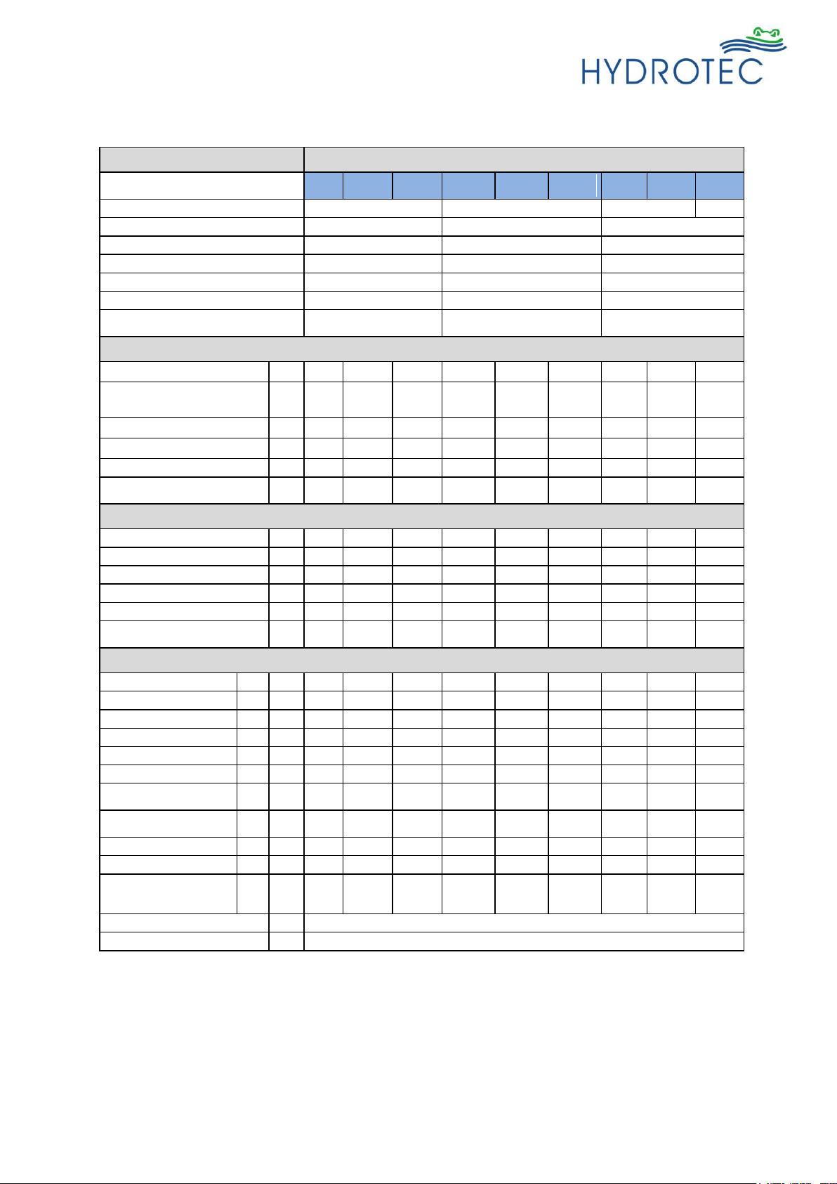
2.1 Technical data
HYDROION® VAS – CS – A
Systems with full salting
(Type A)
25-CS
1 - A
50-CS
1 - A
75-CS
1 - A
125-CS
1,5 - A
150-CS
1,5 - A
200-CS
1,5 - A
250-CS
2 - A
375-CS
2 - A
600-CS
2 - A
Connection mains / soft water line
DN 25 (1")
DN 40 (1 1/2")
DN 50 (2")
DN 80
Drain line (mind.)
DN 50
DN 50
DN 70
Mains electrical connection
230 V / 50 Hz AC
230 V / 50 Hz AC
230 V / 50 Hz AC
Electrical connection (secondary)
12 V AC
12 V AC
12 V AC
Water temperature (min./max.)
5 °C / 30 °C
5 °C / 30 °C
5 °C / 30 °C
Ambient temperature (min./max.)
5 °C / 40 °C
5 °C / 40 °C
5 °C / 40 °C
Operational pressure
(min./max.) 2)
2 bar / 8 bar
2 bar / 8 bar
2 bar / 8 bar
Performance data
Nominal flow
1)
m³/h
2.5
3.5
4.5
6.5
8.0
10.5
13.5
17.0
24.0
Flow rate at blending
(300 ppm to 60 ppm)
m³/h
3.1
4.4
5.6
8.1
10.0
13.1
16.9
21.3
30.0
Pressure loss at rated flow 1)
bar
0.43
0.66
0.88
0.78
0.65
1.14
1.05
1.34
1.94
Capacity at 300 ppm CaCO3 1)
m³
5.3
10.8
16.2
27.3
32.2
43.5
54.9
82.8
132.3
Salt consumption
kg 5 10
15
25
30
40
50
75
120
Waste water volume per
regeneration
m³
0.17
0.36
0.55
0.88
1.06
1.40
1.73
2.62
4.20
Volume and weights
Resin vessel volume
Ltr.
38.4
79.5
115
153
277
277
344
473
704
Quantity of resin
Ltr.
25
50
75
125
150
200
250
375
600
Quantity of gravel
kg 4 7
10
17
40
40
40
58
40
Brine tank volume
Ltr.
140
190
340
460
460
670
920
1000
1500
Regeneration salt supply
kg
50
75
125
175
162
250
325
375
525
Operational weight
(complete unit) max.
kg
125
210
325
465
620
740
925
1210
1750
Dimensions
Height (max.)
mm
1235
1530
1600
1600
1700
1700
2000
2200
2220
Ceiling height (min.)
H
mm
1800
1800
1900
1900
2000
2000
2200
2400
2500
Width (max.)
B
mm
910
960
1160
1360
1550
1730
1980
2050
2480
Depth (max.)
T
mm
600
600
725
850
850
1000
1150
1150
1500
Clearance tank/tank (ca.)
A1
mm
510
530
630
760
820
900
1020
1070
1340
Diameter pressure tank
D1
mm
258
310
363
413
555
555
555
635
779
Diameter brine tank
(min. / max.)
D2
mm
460 /
565
460 /
565
594 /
723
703 /
833
703 /
833
847 /
973
997 /
1123
1015 /
1120
1050 /
1150
Height pressure tank
(incl. foot)
H1
mm
897
± 6
1232
± 6
1344
± 6
1341
± 15
1434
± 15
1434
± 15
1721
± 15
1918
± 15
1892
± 15
Height top control valve
H2
mm
1080
1420
1530
1570
1665
1665
1930
2130
2160
Height brine tank
H3
mm
843
1123
1200
1196
1196
1196
1206
1340
1500
Height feed (mains
water) / discharge
(softwater)
H4
mm
960
1295
1400
1430
1520
1520
1810
2010
2040
Control box (W x H x D)
mm
240 x 170 x 110
Mounting board (W x H x D)
mm
330 x 200 x 10
2. Technical Data
1)
Parameters are dependent on operation mode and water input quality.
2)
At operating pressure min. the flow pressure is decisive, at operating pressure max. the static
pressure is decisive
For the use in the field of boiler feed water, preliminary treatment and reverse osmosis a project
planning is always required performed by our Applications engineering department!
15/98
Last change 10/2018 E-P | Subject to technical modifications
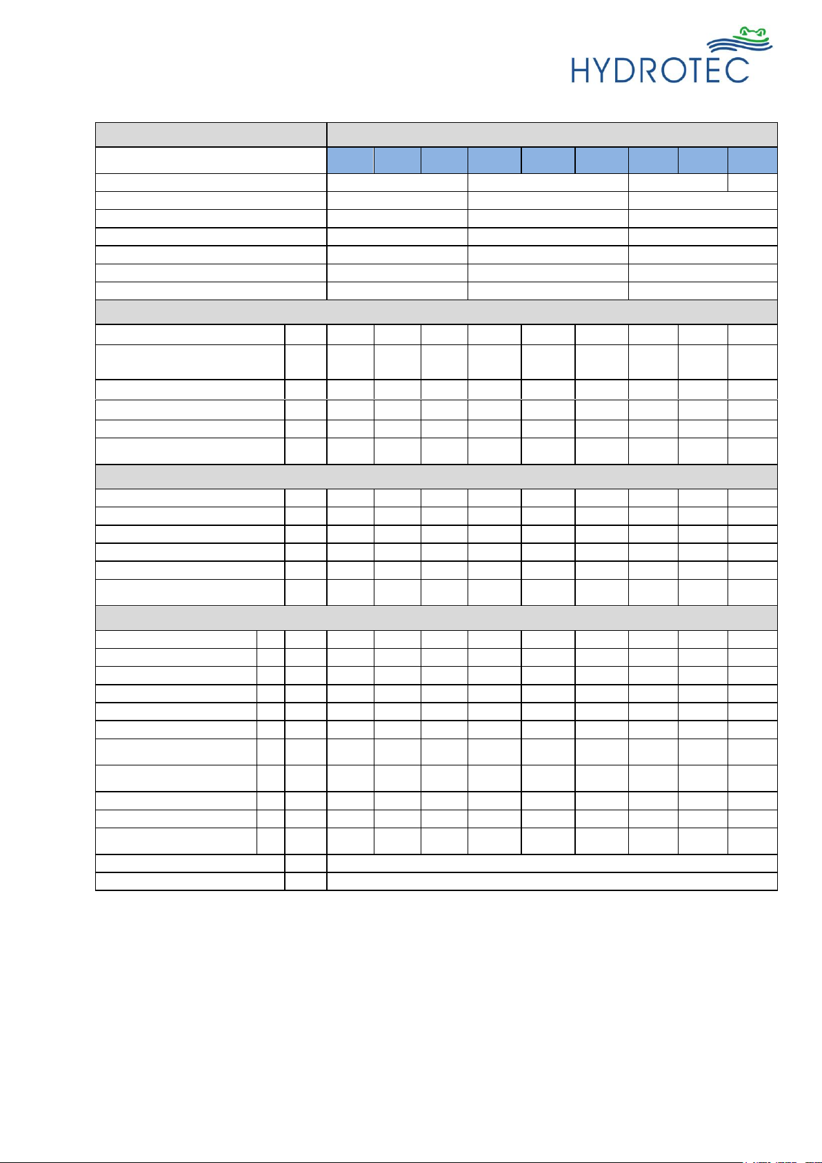
2.2 Technical data
HYDROION® VAS – CS – B
Systems with economise
salting (Type B)
25-CS 1
- B
50-CS 1
- B
75-CS 1
- B
125-CS
1,5 - B
150-CS
1,5 - B
200-CS
1,5 - B
250-CS
2 - B
375-CS
2 - B
600-CS
2 - B
Connection mains / soft water line
DN 25 (1")
DN 40 (1 1/2")
DN 50 (2")
DN 80
Drain line (mind.)
DN 50
DN 50
DN 70
Mains electrical connection
230 V / 50 Hz AC
230 V / 50 Hz AC
230 V / 50 Hz AC
Electrical connection (secondary)
12 V AC
12 V AC
12 V AC
Water temperature (min./max.)
5 °C / 30 °C
5 °C / 30 °C
5 °C / 30 °C
Ambient temperature (min./max.)
5 °C / 40 °C
5 °C / 40 °C
5 °C / 40 °C
Operational pressure (min./max.) 2)
2 bar / 8 bar
2 bar / 8 bar
2 bar / 8 bar
Performance data
Nominal flow
1)
m³/h
2.5
3.5
4.5
6.5
8.0
10.5
13.5
17.0
24.0
Flow rate at blending
(300 ppm to 60 ppm)
m³/h
3.1
4.4
5.6
8.1
10.0
13.1
16.9
21.3
30.0
Pressure loss at rated flow 1)
bar
0.43
0.66
0.88
0.78
0.65
1.14
1.05
1.34
1.94
Capacity at 300 ppm CaCO3 1)
m³
3.9
7.8
11.8
19.9
23.4
31.6
39.9
60.2
96.2
Salt consumption
kg 2 4 6 10
12
16
20
30
48
Waste water volume per
regeneration
m³
0.15
0.31
0.46
0.76
0.92
1.22
1.52
2.28
3.66
Volume and weights
Resin vessel volume
Ltr.
38,4
79,5
115
153
277
277
344
473
704
Quantity of resin
Ltr.
25
50
75
125
150
200
250
375
600
Quantity of gravel
kg 4 7
10
17
40
40
40
58
40
Brine tank volume
Ltr.
140
190
190
340
340
460
460
670
920
Regeneration salt supply
kg
50
75
75
125
125
175
175
250
337
Operational weight
(complete unit) max.
kg
125
210
270
410
580
660
765
1080
1550
Dimensions
Height (max.)
mm
1235
1530
1600
1600
1700
1680
2000
2200
2220
Ceiling height (mind.)
H
mm
1800
1800
1900
1900
2000
2000
2200
2400
2500
Width (max.)
B
mm
910
960
1020
1250
1400
1500
1540
1760
2060
Depth (max.)
T
mm
600
600
600
750
750
850
850
1000
1150
Clearance tank/tank (ca.)
A1
mm
510
530
560
700
770
830
870
980
1130
Diameter pressure tank
D1
mm
258
310
363
413
555
555
555
635
779
Diameter brine tank
(min. / max.)
D2
mm
460 /
565
460 /
565
460 /
565
594 /
723
594 /
723
703 /
833
703 /
833
847 /
973
997 /
1123
Height pressure tank (max.)
H1
mm
897
± 6
1232
± 6
1344
± 6
1341
± 15
1434
± 15
1434
± 15
1721
± 15
1918
± 15
1892
± 15
Height top control valve
H2
mm
1080
1420
1530
1570
1665
1665
1930
2130
2160
Height brine tank
H3
mm
843
1123
1123
1200
1200
1196
1196
1196
1206
Height feed (mains water) /
discharge (softwater)
H4
mm
960
1295
1400
1430
1520
1520
1810
2010
2040
Control box (W x H x D)
mm
240 x 170 x 110
Mounting board (W x H x D)
mm
330 x 200 x 10
1)
Parameters are dependent on operation mode and water input quality.
2)
At operating pressure min. the flow pressure is decisive, at operating pressure max. the static
pressure is decisive
For the use in the field of boiler feed water, preliminary treatment and reverse osmosis is this model
series not suitable!
16/98
Last change 10/2018 E-P | Subject to technical modifications
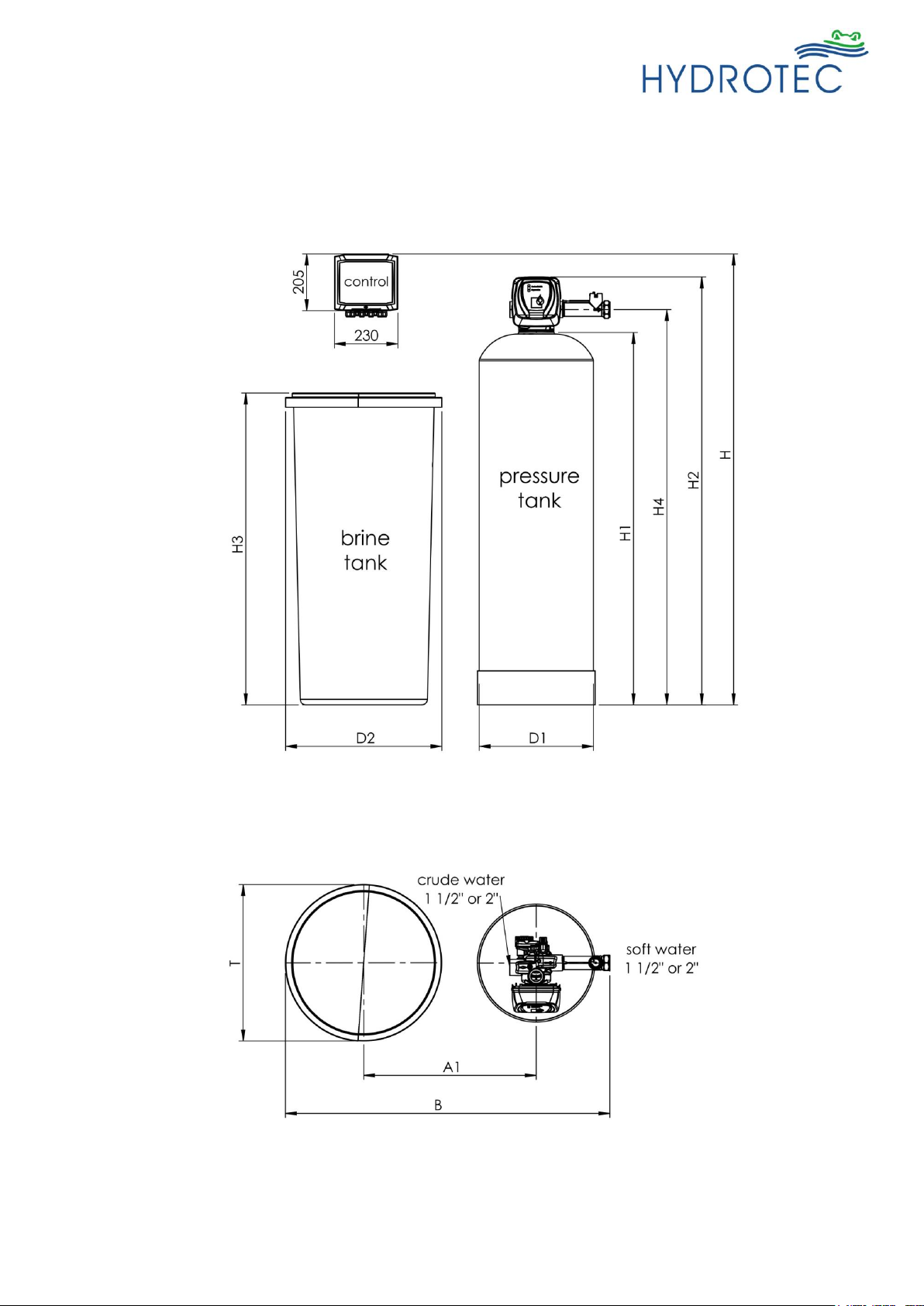
2.3 Installation schematic
Height feed (mains water) / discharge (softwater)
17/98
Last change 10/2018 E-P | Subject to technical modifications
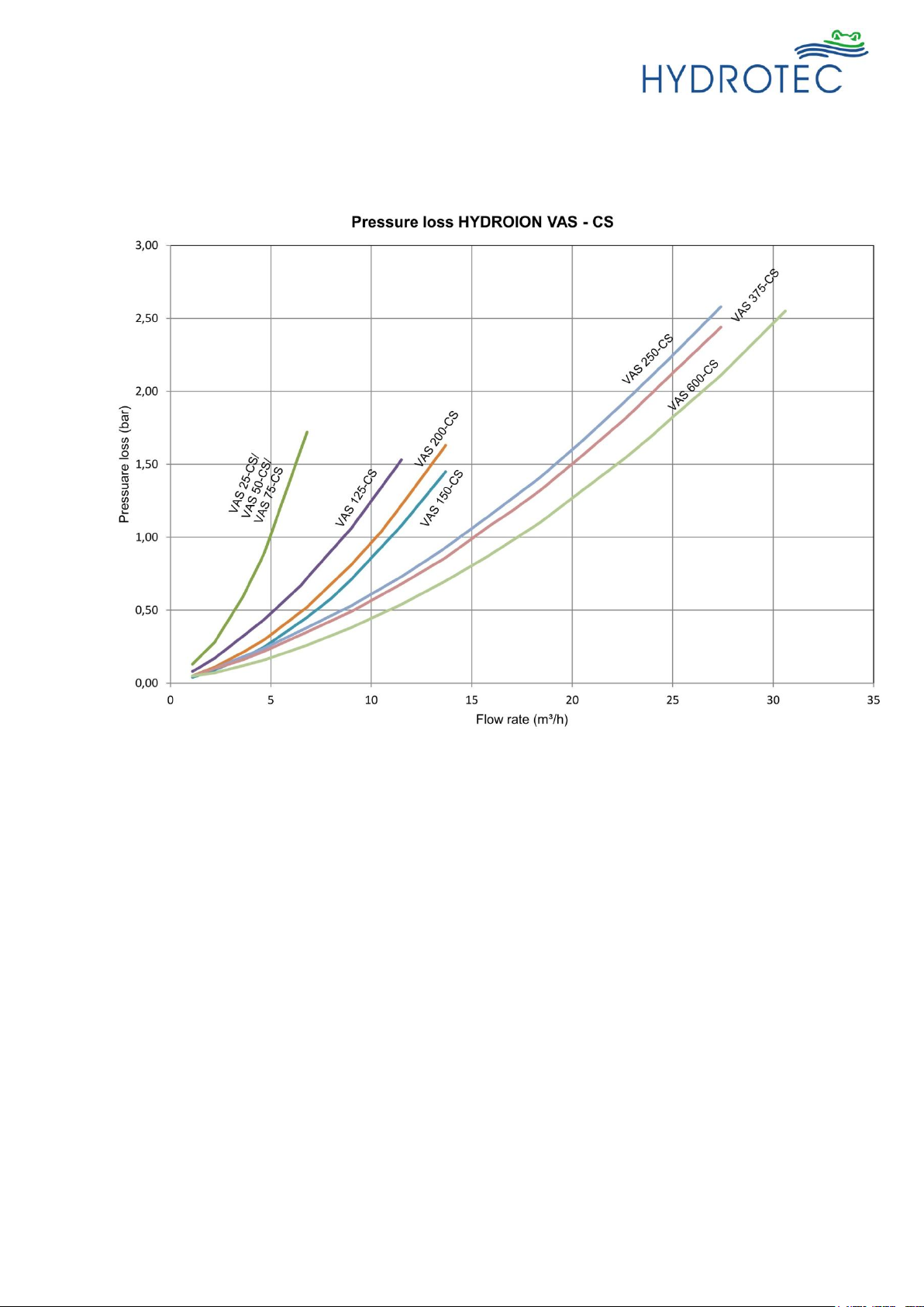
2.4 Pressure loss curve
18/98
Last change 10/2018 E-P | Subject to technical modifications
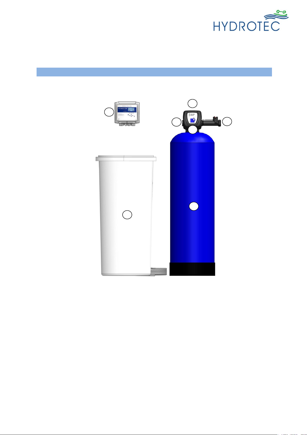
Equipment
Description
HYDRO ION® VAS – CS 1,5
(example)
1 = Resin vessel 1 (pressure tub)
2 = Control valve
3 = Brine tank
4 = Electronic control
5 = Input
6 = Output (softened water)
7 = Wash water drain
Resin vessel
Pressure tank of corrosion-resistant glass-fibre
reinforced plastics with PE-inliner (approved
for foodstuffs) with nozzle (jet) system.
Number: 1
Top threaded connection:
2 1/2“ HYDRO ION® VAS – CS 1
4” HYDRO ION® VAS – CS 1.5
4“ HYDRO ION® VAS – CS 2
6“ flanged HYDRO ION® VAS 600 – CS 2
1 2 3 4 5
6
7
fig.3
3. Scope of supply
3.1 Components
19/98
Last change 10/2018 E-P | Subject to technical modifications
Resin media
Strong acid cat-ion exchange resin to be suited
for drinking water application PFC100E grade.
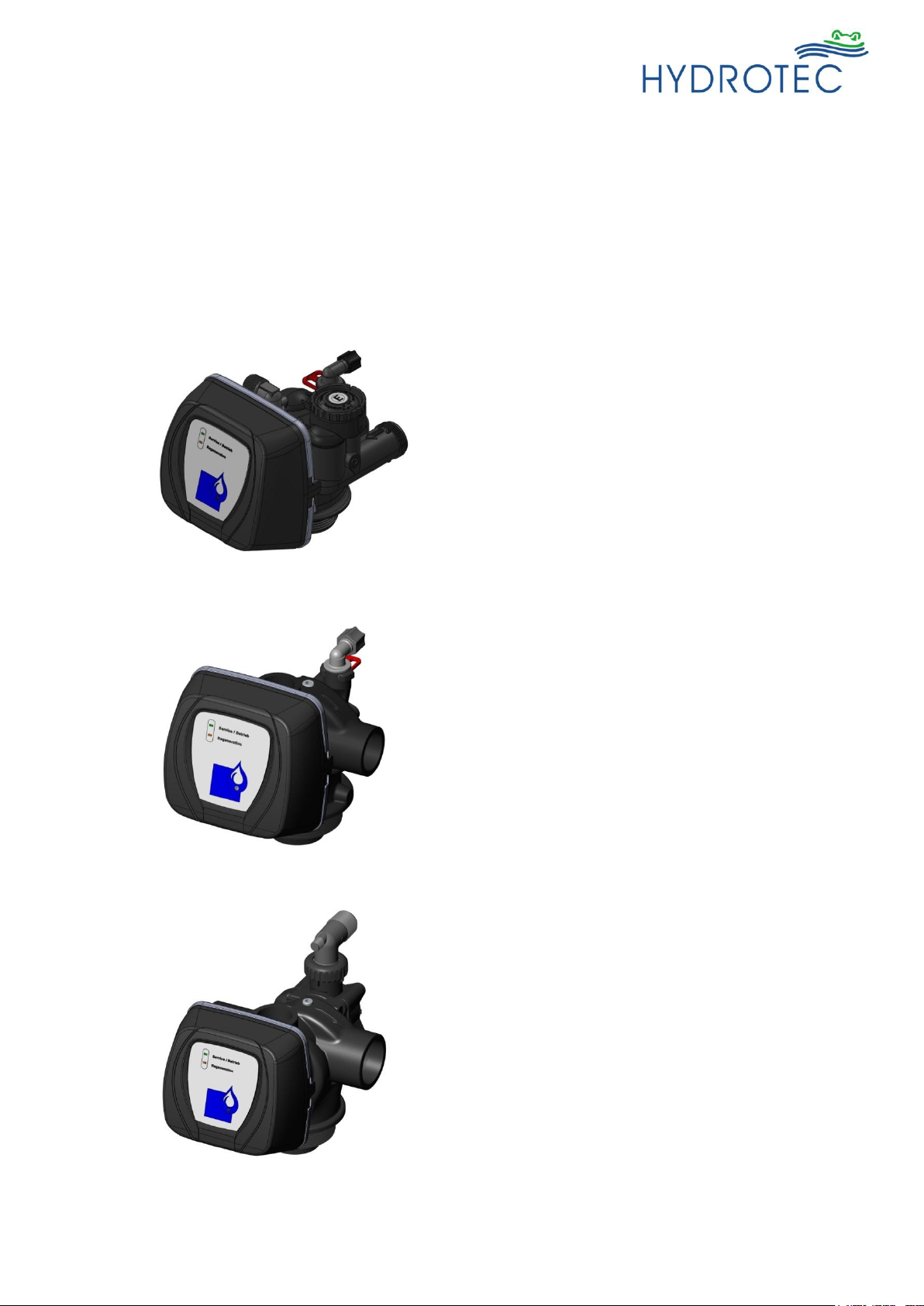
Control valve
Microprocessor controlled, menu driven
system for control of operating modes,
functions and display.
Number: 1
Operating pressure: 2,5 to 8 bar
Operating temperature: 5 to 40 °C
HYDRO ION® VAS – CS 1
Material: Plastics (Noryl)
With top nozzle and
system pcb CB 204
Connections:
Incoming/soft water: 1“ (male)
Brine intake: 3/8“
Waste water: DN 20
Tank connection: 2 1/2“ – 8 NPSM
HYDRO ION
®
VAS – CS 1.5
Material: Brass with epoxy resin
coating and
system pcb CB 204
Connections:
Incoming/soft water: 1 1/2“ (female)
Brine intake: 1/2“
Waste water: DN 20 / DN 25
Tank connection: 4“ – 8 NPSM
HYDRO ION
®
VAS – CS 2
Material: Brass with epoxy resin
coating and
system pcb CB 204
Connections:
Incoming/soft water: 2“ (female)
Brine intake: 3/4“
Waste water: DN 25
Tank connection: 4“ – 8 UN
fig.4
fig.5
fig.6
20/98
Last change 10/2018 E-P | Subject to technical modifications
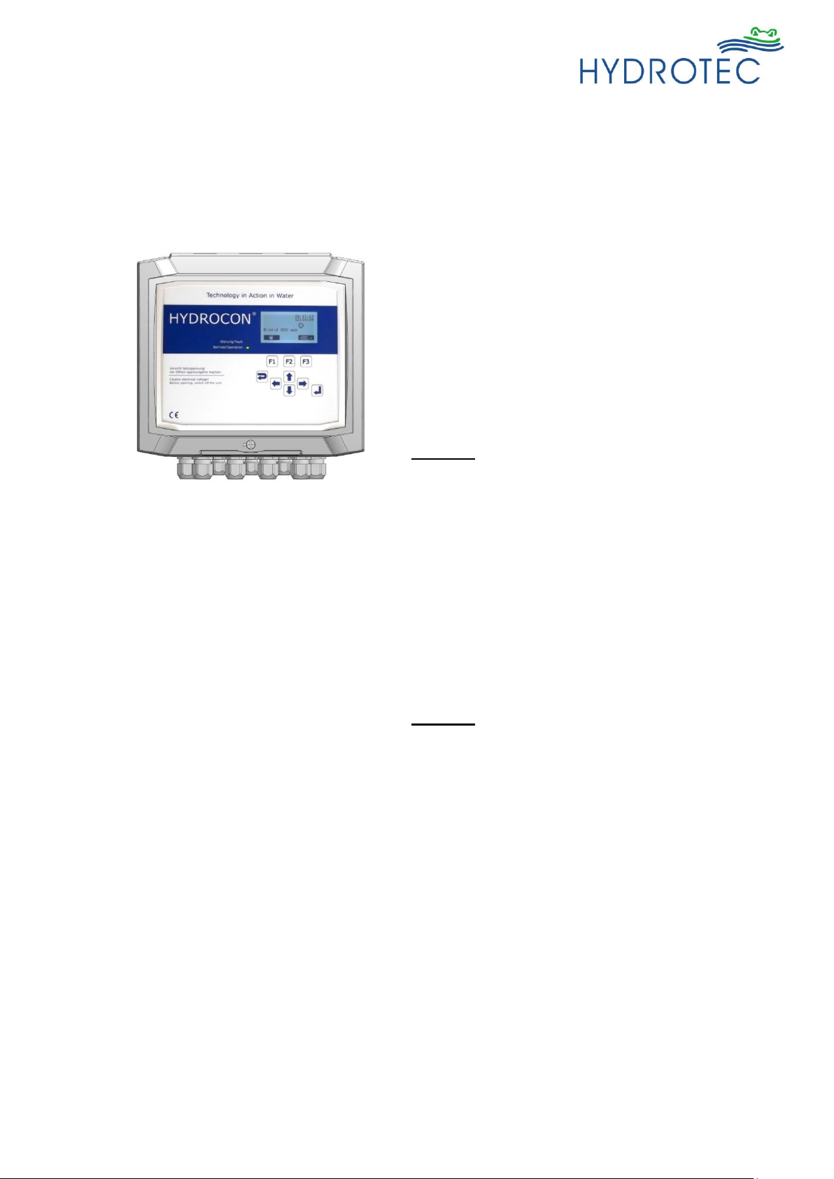
Micro processor control
Micro processor control in wall-mounted
casing, menu driven for different operation
modes such as:
- volume control with temporally priority circuit
- time control
- quality control in combination with
hardness control
- forced regeneration
- water refresh
- automatic disinfection
- external release
- external regeneration
- “brine alarm” - sensor in brine tank
(Function even at 2 brine tanks)
- “pressure alarm” - sensor
Hygienic operation of softener in two steps:
Phase 1: Refresh
(Interval rinsing / water-refresh)
For prevention of stagnation phases a switch
between both vessels takes place in short
intervals. Stagnated water is minimized in
stand-by.
Interval rinsing: At this setting the stagnated
water (defined volume) is led directly into the
drain line.
Water-refresh: In contrast to interval rinsing
the stagnated water (defined volume) is led
into the soft water system instead.
Phase 2: Disinfection
Is possible during regeneration.
Functions and messages:
- Diagnostic mode
- Error list (emBrick list) for errors
occurring during operation of the
controller
- Information mode with display on
monitor
- LED signal malfunction / operation
- universal output (maintenance /
regeneration / brine lack)
The electronic controller is pre-installed and
pre-assembled on a mounting plate and ready
for wall mounting.
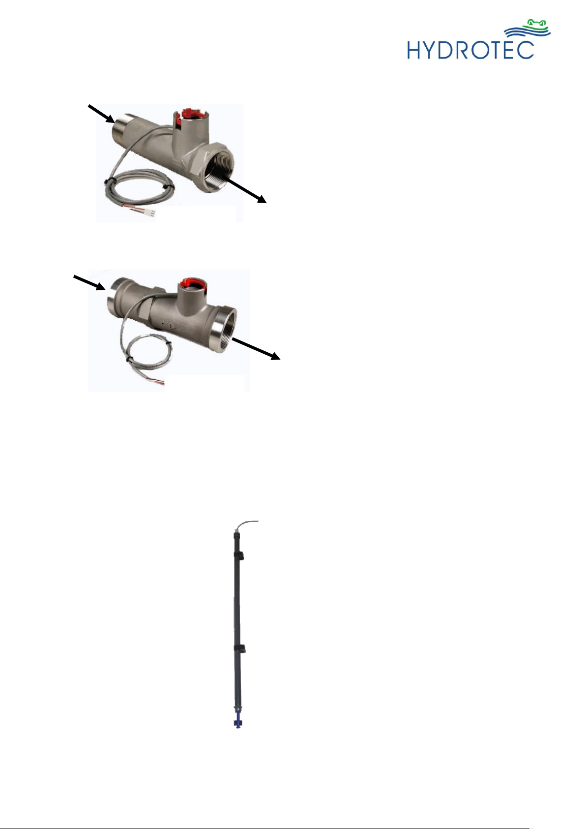
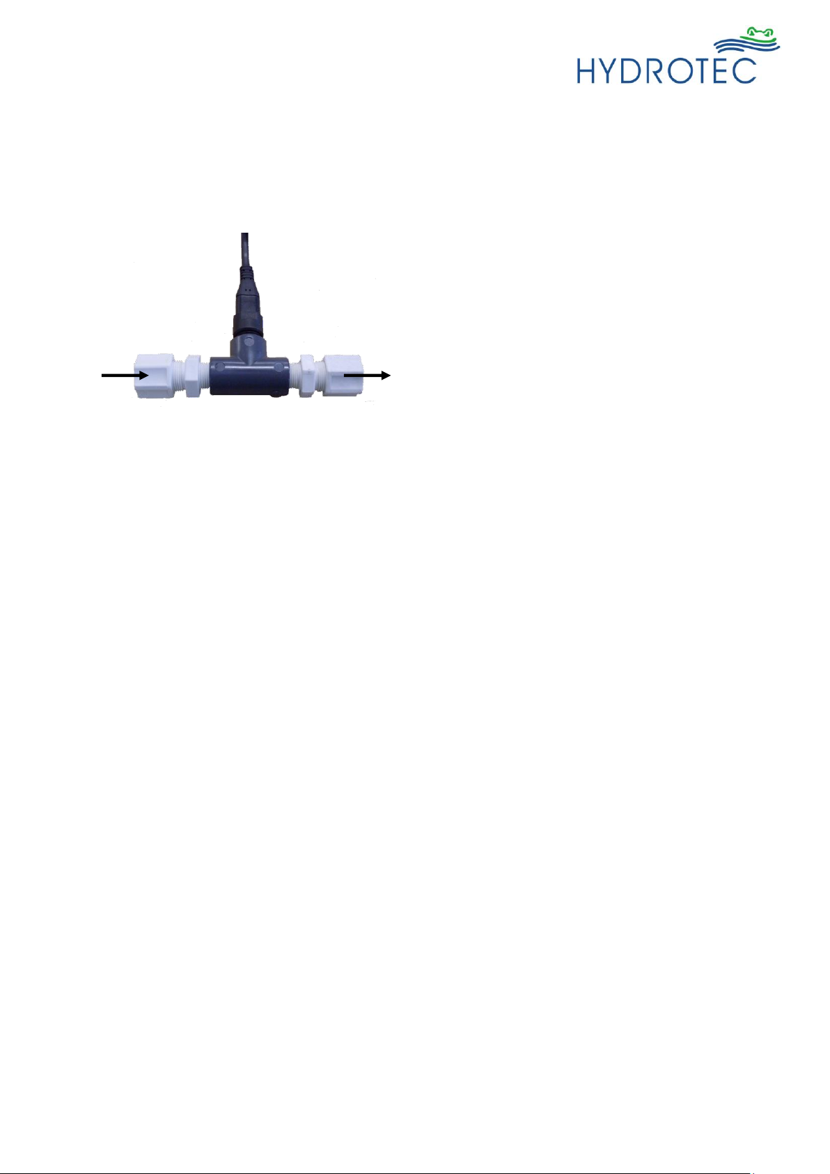
Water meter
HYDRO ION® VAS – CS 1
The water meter 1” is integrated in the casing
of the control valve.
fig.7
21/98
Last change 10/2018 E-P | Subject to technical modifications
HYDRO ION® VAS – CS 1,5
Water meter as external installation unit,
mounted direct to the soft water output.
Connection: input 1 ½“ external thread
output 1 ½“ internal thread
Voltage: 12 V AC
Cable suited to connect the control to the central
control valve 1.
HYDRO ION® VAS – CS 2
Water volume meter as external installation unit,
mounted direct to the soft water output.
Connection: input 2“ external thread
output 2“ internal thread
Voltage : 12 V AC
Cable suited to connect the control to the central
control valves 1.
Brine tank
Storage tank for regeneration salt, designed as
tank with sieve base, brine tube and overflow.
Number: 1 off
Material: Polyethylene
Brine exhaust
Installed in the brine tube of the brine tank,
consisting of:
Brine safety valve
Float switch
Brine hose
Brine alarm sensor
Brine alarm sensor to control the brine level in
the tank, installed in the brine tube and consisting
of:
- float switch
- protective tube
- electric connection cable to micro processor
control
Switching capacity: max. 10 W/VA
Voltage: max. 12 V
Currency: max. 0.5 A
Connection cable
Connection cable
fig.8
fig.9
fig.10
22/98
Last change 10/2018 E-P | Subject to technical modifications
Chlorinator (Option)
Chlorinator used for the automatic disinfection
during regeneration phase of softener, consisting of:
- electrodes installed in PVC assembly element
- control cable for the connection to the micro
processor control
Control voltage: max. 15 V
Connection: 3/8“ (VAS – CS 1)
1/2“ (VAS – CS 1,5/ 2)
The electrodes are activated automatically once the
brine intake cycle of the regeneration phase starts.
Chlorine is produced that starts the disinfection of
the resin bed.
The process is finished automatically once the
programmed time period for disinfection is elapsed.
The electrodes are de-activated again.
Measuring kit permanent hardness
The below measuring kits shall be available for
setting and control of the system:
Determination of permanent hardness:
Measuring range up to 760 ppm
Control cable
T-fitting
Chlorinator
fig.11
23/98

Last change 10/2018 E-P | Subject to technical modifications
Back flow prevention device
Connection size dependent on
customer’s request
(Nom. flow to be considered!)
To separate drinking water from non drinking water up to
and including liquid category 4 (DIN 1988, part 4) for
systems according to DIN 1717 with controlled
separation (installation type 2 according to DIN 1988)
with integrated differential pressure controlled and
maintenance friendly safety cartridge, non-return system,
three test valves and drain connection.
Material: red brass
without dead space, noise
tested as per ISO 38222, with
SVGW/DVGW-certificate
Temperature: max. 60 ° C
Nom. pressure: PN 10 (connection screwing
with external thread)
Pressure loss: 1.0 bar
Back flow prevention to be in accordance with local
regulations.
Connection local incoming/
soft water pipe
Assembly mount
HYDRO ION® VAS – CS 1
With blending
Art.-No.
Excluding blending
Art.-No.
The mount replaces the by-pass line to be provided
locally. Two valves stop the supply and discharge and
allow service work. The fitting can be used including or
excluding blending.
Material: corrosion resistant
red brass as per DIN 1705
Water temperature: max. 90 ° C
Pressure step: PN 10
Connections : R 1“
Installation length: 166 mm
HYDRO ION® VAS – CS 1,5
With blending
Art.-No
Excluding blending
Art.-No.
Material: corrosion resistant
red brass as per DIN 1705
Water temperature: max. 90 ° C
Pressure step: PN 10
connections: R 1 1/2“
installation length: 200 mm
HYDRO ION® VAS – CS 2
There is no mount available for such sizes. Installation of
softener has to be realized in rigid pipe work.
3.2 Accessories
24/98

Last change 10/2018 E-P | Subject to technical modifications
External blending
Blending unit DN 32
Art.-No.
Blending unit DN 50
Art.-No.
Fully automatic operating blending valve for installation
in bypass.
Material: corrosion resistant
red brass as per DIN 1705
Water temperature: max. 90 °C
Pressure step: PN 10
Connections : R 1 1/4“ (DN 32)
Installation length: 130 mm
Installation length: R 2“ (DN 50)
Installation length: 139 mm
Flexible hose
HYDRO ION® VAS – CS 1
Flexible hose - Art.-No.
HYDRO ION® VAS – CS 1,5
Flexible hose - Art.-No.
2 flexible hoses for system connection
Dimensions: 2 x 1“ (ÜM)
Length: 800 mm
2 flexible hoses for system connection
Dimensions : 1 1/2“ (AG) x 1 1/2“ (ÜM)
Length: 1000 mm
Regenerant
Art.-No.
In form of tablets (not granular!)
25 kg PE bag (Not available from Hydrotec UK Ltd.)
25/98

Last change 10/2018 E-P | Subject to technical modifications
Index chapter IV – Installation and assembly
Page
1. General information 27
2. Installation location 28
3. Work prior to assembly 28
Control of shipment 28
Drain connection 28
Incoming and soft water pipe 28
3.1 Filling of filter vessel with quartz gravel and exchange resin 29
4. Hydraulic connections at control valve 31
Control valve 1“ HYDRO ION® VAS – CS 1 31
Control valve 1 1/2“ HYDRO ION® VAS – CS 1.5 31
Control valve 2“ HYDRO ION® VAS – CS 2 31
Brine line 32
Brine lack sensor 32
Chlorinator 32
Wash water connection (drain) 32
5. Electric connections 33
Mains connection 33
Connection pcb control valve 33
Connection water volume meter 34
26/98
Last change 10/2018 E-P | Subject to technical modifications
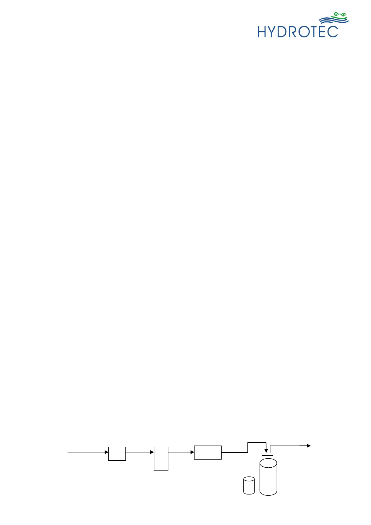
Fine filter
System sep.
Water meter
Incoming
water
Softener
fig.12
1. General information
The HYDRO ION ® VAS – CS softener is designed as Simplex system consisting of one resin vessel
(pressure vessel) with ion exchange resin and support quartz gravel as well as one control valve on
top of the filter vessel each. All operation modes are realized by means of a micro processor control.
The softener system HYDROION® VAS 25 is filled with exchange resin ex works. The system
up to “VAS 600” has to be filled with exchange resin in situ (chapter IV section 3.1).
The resin vessel for the HYDROION® VAS range is dispatched empty for handling purposes
and must be filled with the gravel and ion exchange resin on site (see Chapter 6.5.1.). The resin
will be supplied separately in 25l bags.
It is the responsibility of the commissioning engineer to fill the resin vessel with the gravel and
resin. Hydrotec (UK) Ltd. will perform this service during commissioning visit.
Necessary pipe connections to the central control valve must be performed on site.
Softener is controlled via water flow meter installed in the soft water pipe.
The control settings are programmed in the microprocessor control unit.
Information and parameters such as time, regeneration status, residual capacity, water
consumption, operation days, functions and actual state for inputs and outputs are shown in the
display of the microprocessor control unit.
The brine container / salt bin which holds the tablet salt regenerant must be located immediately
adjacent to the resin vessel.
The supply of the regenerant to the control valve of the respective vessel is by float valve and
hose line into the vessel.
Wash water (waste water) is discharged to drain.
Incoming water is drinking water
According to standard EN1717 (DIN 1988), water softeners have to be provided with the
following safety fittings:
- Black flow prevention device
Due to the installation of a back flow prevention device, the pipe work is protected against
the return of treated drinking water into the drinking water system.
Please consult local regulation.
- Protective filter
Suited for the protection of the pipe installation and the softener against malfunction and
corrosion damage that can arise by foreign particles such as rust, sand etc.
According to standard DIN 13443-1, a filter has to be installed in the pipe before the system
separator and just after the water meter in case of metal pipe work.
The installation of a protective filter is recommended for plastic pipe work as well.
27/98
Last change 10/2018 E-P | Subject to technical modifications
Delivery check
Prior to starting assembly, the equipment must be
checked for completeness and possible transport
damage.
Any deviation must be notified immediately.
Waste water connection
The local waste water connection must be provided as
free discharge as per EN1717 (DIN 1988).
The cross section of the drain must be sufficiently
dimensioned (DN 50 at least).
Mains / incoming and soft
water pipes
The mains water and soft water pipes must be designed
locally in the required cross section and in the necessary
position in relation to the system.
Materials for soft water pipes should be plastic or
stainless steel.
Furthermore DIN 19636 (section: “protection against bacterial contamination”) must be observed:
“As water softening systems, especially at discontinuous operation, are vulnerable to bacterial
contamination, this must be prevented by means of suitable constructive or chemical-physical
measures.”
In order to keep that DIN 19636, a forced regeneration after 4 days (96 hours) has to be
programmed in the controller of the HYDRO ION ® VAS – CS softener system.
Installation of a chlorine producer into the brine hose is provided ex works for the system designs
VAS CS – A (systems with full salting) and B (systems with economic salting).
The chlorinator is actuated via the micro processor control unit.
The installation of the system must be carried out by trained and qualified personnel.
DIN 1988, DIN EN 12506 and DIN EN 806 are to be observed during installation.
2. Installation location
The below has to be guaranteed in respect of the installation and operation of a softener:
The HYDRO ION® VAS - CS softener is to be installed in a frost-protected area.
The ambient temperature must not drop below 5°C and not exceed 40°C.
A free discharge to the drainage system as per EN 1717 (DIN 1988) for waste water and
overflow of brine tank in accordance with the discharge volume is to be provided locally.
Installation should be located on even floor with level tolerances as per DIN 18202.
The minimum installation dimensions are shown in the dimensional drawings and table (see
chapter III).
An electrical connection of 230 V, 50 Hz, 3 A fused spur is to be provided locally for the
operation of the micro processor control.
In order to avoid flooding by leakage, the installation location must be provided with ground
drainage discharge or leakage monitor with corresponding alarm.
3. Work prior to assembly
28/98
Last change 10/2018 E-P | Subject to technical modifications
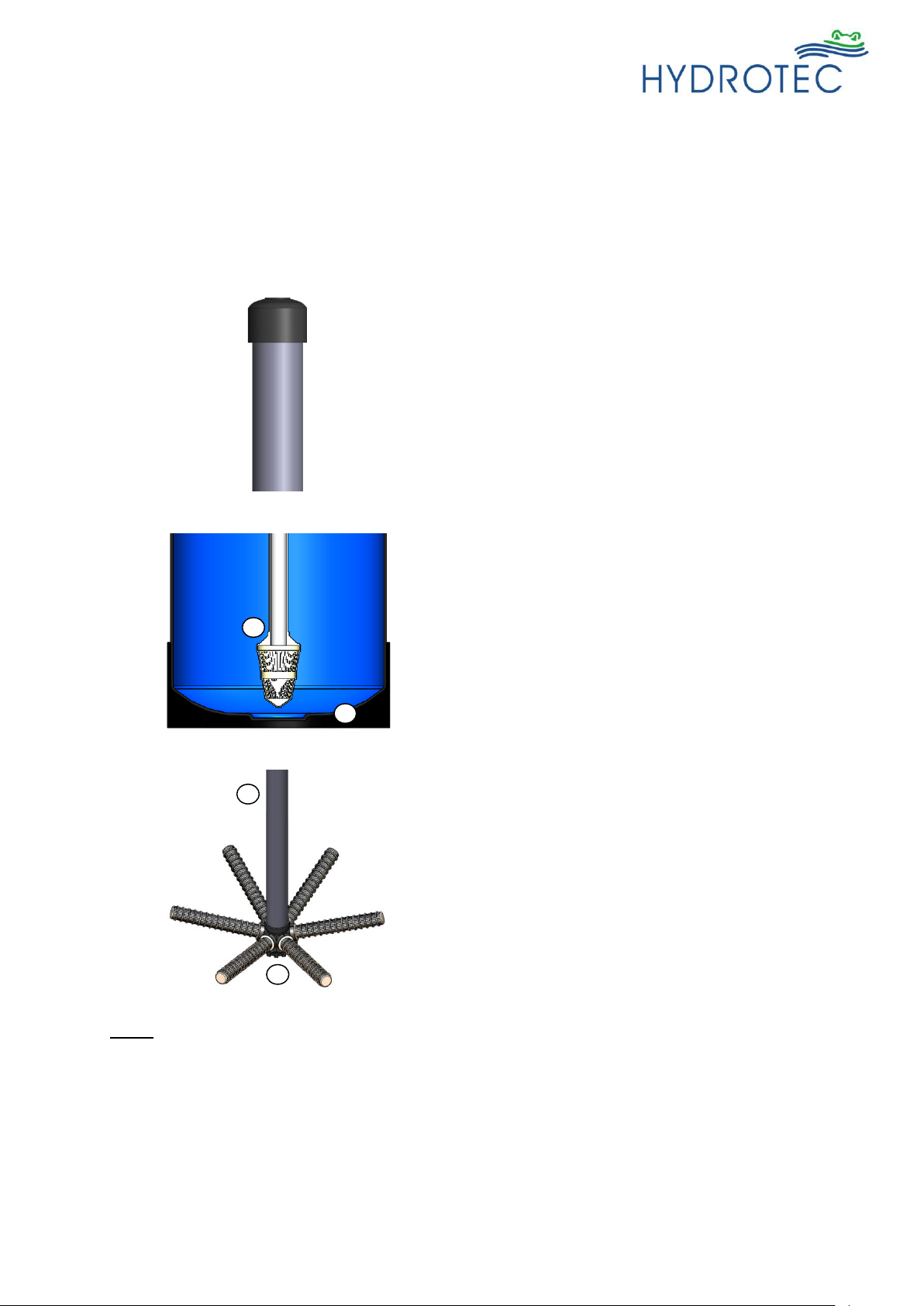
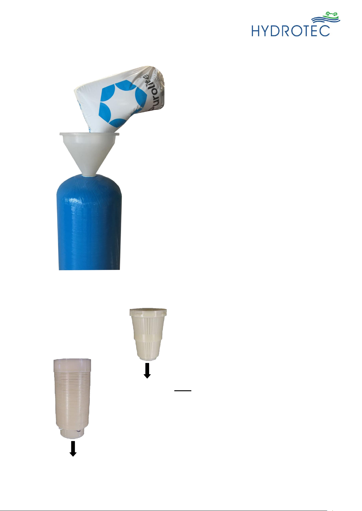
Seal the upper pipe opening of the riser with
insulating tape in order to prevent resin or
quartz gravel entering the riser tube during
filling of the resin tank.
Lower distributor (1“ systems)
1 = filter on end of riser tube
2 = resin vessel base
Position the riser tube in the resin vessel in
such a way, that the riser tube stands in the
middle of the container base.
Star-type distributor (1 ½“ and 2“systems)
1 = nozzle rod
2 = star-type distributor
The star-type distributor shall be put together
and placed in the vessel in a way that it
stands on the vessel base.
The pipe cover must not be forgotten!
nozzle rod
protection cap
2 1 1
2
fig.13
fig.14
fig.15
3.1 Filling of resin vessel with quartz gravel and exchange resin
Assembly of resin vessel (pressure vessel) and brine tank, whereby a sufficient area must be
available for operation and maintenance as well as supply and discharge lines.
(Installation schematics see appendices 1)
Note:
The quartz gravel volume is sufficient for both filter vessels and packed in the respective required
quantity.
It is recommended to wash the quartz gravel prior to being filled into the vessel in order to eliminate
any possible contamination.
(Best in a bucket under flowing water and constant stirring)
29/98
Last change 10/2018 E-P | Subject to technical modifications
Upper distributor
HYDRO ION® VAS – CS 1
Upper distributor
HYDRO ION®
VAS – CS 1,5
(Di 50 mm)
VAS – CS 2
(Di 63 mm)
Filling of filter vessel as below:
Step 1:
Fill the resin vessel to approximately one quarter
of its volume with clean water.
Step 2:
Fill the quartz gravel in the resin vessel.
A good distribution must be guaranteed!
Step 3:
Separate the resin and fill it in the vessels.
A good distribution must be guaranteed!
The respective quantity to be filled into the
vessels are shown in chapter III / point 2.1 and
2.2 (table with technical data).
Step 4:
Clear any contamination, such as resin off the
threaded opening to the vessel, with clean water.
Step 5:
The closure of the nozzle rod must be removed
again.
Step 6:
The control together with top distributor must be
mounted on the vessels and the unit be aligned.
It has to be guaranteed that the nozzle rod can
be inserted into the opening of the control valves
without problem.
Step 7:
The prepared connections for incoming and soft
water must be connected.
Note:
All sealings (O-Ringe) at the vessel
connection of the control valves must not be
damaged and fit straightly.
to control valve
to control valve
nozzle rod
nozzle rod
fig.16
fig.18
fig.17
30/98

Last change 10/2018 E-P | Subject to technical modifications
Control valve 1“ - HYDRO ION® VAS CS 1
1 = Mains water connection (inlet)
2 = Soft water connection (outlet)
3 = Connection for brine line
4 = Waste water connection
Control valve 1 1/2“ - HYDRO ION® VAS CS 1.5
Control valve 2“ - HYDRO ION® VAS CS 2
3
1 2 4 3 2 1 4 2 1
4
fig.18
fig.19
fig.20
Water meter
4. Hydraulic connections at control valve
31/98

Last change 10/2018 E-P | Subject to technical modifications
Brine line
The brine is taken from the brine tank by means of a hose.
Brine is drawn in by the control valve and flows through the
intake pipe to the injector, passing the injector, before
reaching the filter media. The injector is used to limit the
brine quantity that is dependent on the quantity of filter
media.
The brine intake hose has to be fixed to the hose connection
of the brine valve (in brine tank). The hose must be fixed to
the connections of the control valve.
HYDRO ION® VAS - CS 1
Control valve 1“: connection 3/8“
HYDRO ION® VAS - CS 1.5
Control valve 1.5”: connection 1/2“
HYDRO ION® VAS - CS 2
Control valve 2“: connection 3/4“
The waste water hose that is included in the delivery scope
must be connected in an appropriate length and size to the
local drain.
Brine lack sensor
The brine lack sensor is mounted already in the brine tube of
the brine tank and has to be connected electrically to the
micro processor control.
Chlorinator
If necessary and ordered, the
chlorinator is already
mounted in the brine intake
pipe.
Waste water connection
Waste water connection of control valve 1“: 3/4“
Waste water connection of control valve 1 1/2“: 3/4“ or 1“
Waste water connection of control valve 2“: 1“
The waste water hose must be fixed in an appropriate length
to the connection leading into drain.
It must be guaranteed that discharge of waste water into the
local drain (channel) is without any pressure applied.
Otherwise, regeneration takes place whereby no brine is
drawn in.
To control valve
From brine tank
fig.21
32/98

Last change 10/2018 E-P | Subject to technical modifications
Mains connection
The control in wall mount casing must
be installed at eye level and easily
accessible!
A safety socket must be provided locally next to
the mains cable of the micro processor control.
Permanent voltage must be provided
(230 V / 50 Hz).
Do not use the lighting circuit!
Figure 23 shows all electrical supplies and
control lines to the micro processor control unit.
1 = Power supply
2 = Connection cable chlorinator
3 = Connection cable brine level sensor
4 = Connection cable control valve 1 (A)
5 = Connection cable control valve 2 (B)
Connection pcb control valve
Connections to terminal of pcb of control valve
(from top to below)
Terminal
Magenta 29 / 38
Grey 28 / 37
Black 27 / 36
Red 26 / 35
Blue 25 / 34
Brown 24 / 33
White 23 / 32
Yellow 22 / 31
Green 21 / 30
1 = Connection motor control valve
2 = Connection water flow meter
1
1
2
fig.23
3
2
4
5
fig.22
Important!
All pipe connections must be done without any tension applied on. If necessary, the
subsequent pipes must be provided with corresponding mounts or supports.
Hoses must not be bent and hose connections must be screwed tight.
Waste water, overflow and discharge lines must be provided from the connections at the
control valve until waste water drain with an appropriate inclination.
The waste water must be allowed to drain without backflow.
Backflow is not allowed for hygienic reasons!
5. Electrical connections
33/98

Last change 10/2018 E-P | Subject to technical modifications
Connection water flow meter
HYDRO ION® VAS – CS 1
The water meter is firmly installed in the soft water
output of the valve in case of control valves 1” and
is electrically connected to the pcb by means of
plug cable (see figure 18).
HYDRO ION® VAS – CS 1,5
HYDRO ION® VAS – CS 2
The water meter is installed in the output of the soft
water line in case of control valves 1.5“ and 2“.
Electrical connection is realized by means of plug
cable at the control valve.
Water meter
Control valve
fig.24
All work at electrical equipment of the softener shall be
carried out by an authorized expert only!
Note!
Since there is the risk of germ formation, it is recommended to disinfect the softener after
vessel filling and short before commissioning.
34/98

Last change 10/2018 E-P | Subject to technical modifications
Index Chapter V – Micro processor control
Page
1. HC - SOFTENER 36
1.1 Display / LED’s / Operating keys 37
1.2 Display content whilst the controller is run up 37
1.3 Main display – view 38
1.4 Access levels 40
2. Menu survey 41
3. Alarm 42
3.1 Acknowledge alarm 42
3.2 Alarm records 44
4. Total hardness 45
5. Operation mode 45
6. Protocol settings 46
7. SD-Card (messaging) 46
8. Language 47
9. System time 46
10. System date 47
11. Information 47
12. Menu structure 48
13. Electrical installation / wiring / terminal posts 51
13.1 Installation and commissioning 52
13.2 Technical data HC – softener controller 53
13.3 PCP equipment and terminal charge 54
13.4 Fine fuses 60
14. Parameter settings HYDROION® VAS – CS 61
35/98

Last change 10/2018 E-P | Subject to technical modifications
1. HC – SOFTENER
Our HC SOFTENER controllers ensure a regulation and control of operating process and
regeneration of single unit.
Regeneration can be released by different modes. Volume controlled with time priority (e.g. forced
regeneration after 4 days). A hundred percent time controlled with a pre-set regeneration interval.
Quality controlled regeneration, for example in conjunction with a hardness control device that
supplies an external contact input in case of hardness break, is possible as well.
Different VFC outputs are given to control the operation of the softener:
External regeneration release
Salt lack in brine tank
Pressure shortage
The universal VFC output can be programmed for the below functions:
Warn signal
Regeneration active
Brine lack
An additional VFC relay output confirms possible failure records.
Both relay outputs are designed as VFC alternator.
Several VFC-affected outputs are available for power supply and for the approach of possible
additional plant components:
Brine pump
Circulation pump
36/98

Last change 10/2018 E-P | Subject to technical modifications
HC – Applikation
SOFTENER = softener controller
Software-Version
Arrow keys
Input key/
Enter/CR
Function keys(charge
acc. below display)
Escape
LED operation
LED error
1.1 Display/LED’s/ Operating keys
1.2 Display content whilst the controller is run up
The controller is switched-on with the ON/OFF button (left side at casing) and supplied with mains
voltage. The below display is shown when the controller is run up:
37/98

Last change 10/2018 E-P | Subject to technical modifications
LED green – ON – Vessel in operation
Vessel number –
Vessel 1 in front view
1.3 Main display / view
Two or three different main displays / views exist dependent on plant construction, in between the
controller is switching automatically.
Main display with date, time and software version
Display for filter in operation – identical for all plant constructions
- total capacity that can be treated
- available residual capacity
- actual flow
- time remaining until release of forced regeneration (option)
Ready for operation display – in case of Duplex system only
38/98

Last change 10/2018 E-P | Subject to technical modifications
LED green – OFF – Vessel in regeneration
Regeneration display
- actual regeneration phase
- time remaining of regeneration phase
At the beginning of regeneration the following messages are shown on display.
- Pre-regeneration filter 1
- Pre-operation filter 1
These messages are displayed on the screen until the control valve is in their correct end position.
39/98

Last change 10/2018 E-P | Subject to technical modifications
Regeneration display – release of regeneration locked
- brine formation time not yet finished/elapsed
- lock time active
1.4 Access levels
The controller has four access levels to avoid access by unauthorized persons.
Example for input of password:
Passwords
There are 4 access levels with the below passwords:
Level 1 [user password]: 1111 plumber
Level 2 [admin password]: 2222 supplier
Level 3 [engineer password]: plant engineer
Level 4 [super password]: plant engineer
40/98

Last change 10/2018 E-P | Subject to technical modifications
2. Menu survey
The main menu is called via the keys F3 or Enter. Different functions and settings can be called
from the main menu as below:
Main menu
Alarms
Settings
Total hardness
Service
Operation mode
Protocol Setting
SD-Card
Language
System Time
System Date
Information
The desired menu point can be achieved and selected via the keys F3 or Enter.
The controller returns to any higher menu via the keys F1 or Escape. If any setting was modified,
confirmation is required prior returning to main view that the new setting must be stored.
The respective necessary release must be confirmed to select the different menu points
(see topic 1.4).
These are:
Alarm no password required
Settings Level 1 > plumber
Total hardness no password required
Service Level 3 > plant engineer
Operation mode no password required
Protocol Setting no password required
SD-Card nor password required
Language no password required
System time no password required
System date no password required
Information no password required
41/98

Last change 10/2018 E-P | Subject to technical modifications
LED red - ON
3. Alarm
3.1 Acknowledge alarm
Immediately upon release of an alarm, the below display is shown with the number of actual alarms
and the reason for the record.
The controller returns to main menu view via the keys F1 or Escape.
The alarm record is maintained and can be called anew via the main menu.
The failure LED lights red for the duration of an alarm record.
The alarm is acknowledged via the keys F3 or Enter.
NOTE: Any failure must be eliminated prior being acknowledged.
Example 1:
Alarm „brine lack“
That is caused if regeneration is released but no saturated brine is available or
if salt must be added to the brine tank
Salt must be refilled into brine tank
A brine formation time (ca. 2 to 3 hours) must be allowed to pass
The alarm is automatically acknowledged by the controller once saturated brine is available
as the float in the brine tank rises and thus, closes the input contact
The number of alarms is reduced to zero / the red LED extinguishes
42/98

Last change 10/2018 E-P | Subject to technical modifications
Example 2:
Pre-warn „power failure“
“power failure“ warning is shown in the controller
The warning record is shown even after the controller has been switched off and on again
If power supply was interrupted for a longer time period, no flow was determined during such
period and the capacity was not reduced
Manual regeneration is worthwhile then to avoid overriding the plant capacity
The warning record is acknowledged via the keys F3 or Enter
NOTE:
If several failures and alarms are evident, these must be eliminated and acknowledged all
one after the other.
43/98

Last change 10/2018 E-P | Subject to technical modifications
Record
Failure
Reason / background
Action
Pre-warn
Maintenance
necessary
Maintenance interval
soon running out
Arrange for maintenance soon and
confirm in menu
Alarm
Maintenance
necessary
Maintenance interval ran
out
Arrange for immediate maintenance
and confirm in menu
Pre-warn
Power failure
Separated for mains of
power failure
Acknowledge failure
Pre-warn
Brine lack
No saturated brine in
brine tank
Add salt into brine tank
Alarm
Brine lack
No saturated brine in
brine tank and a
regeneration is due to be
released
Add salt into brine tank
Pre-warn
Chlorinator
Blockage
The actual current is
outside the tolerance for
nominal current
Deposit on chlorine electrode
clean or replace
Pre-warn
Chlorinator
Blockage
The duration of the
chlorine production is
higher than the brine
intake period
Check brine intake period and
chlorine production duration and
adjust if necessary. Alarm delay set
too low
Alarm
Chlorinator
Saturation
The required current
cannot be achieved
even with quite high
voltage
Too low brine saturation
add salt tablets
possibly check hydraulics of brine
intake
Alarm
Chlorinator
Short circuit
Hardware error or false
terminal charge
Check installation
Alarm
head 1/2 time
exceeded
Move time of valve
motor too long
Check plug connections at valve and
terminals in the controller
Alarm
head ½ time
increments
Piston position not
reached
Check plug connections at valve and
terminals in the controller
Alarm
head 1/2 stdby current
Hardware error
Check pcb’s and terminals
Alarm
head 1/2 tract. current
Hardware error
Check pcb’s and terminals
Alarm
head 1/2 high current
Hardware error
Check pcb’s and terminals
Alarm
head 1/2 low voltage
Hardware error
Check pcb’s and terminals
Alarm
head 1/2 high voltage
Hardware error
Check pcb’s and terminals
Alam
Alternator low current
Hardware error
Check pcb’s and terminals
Alarm
Alternator high current
Hardware error
Check pcb’s and terminals
Alarm
Alternator time
exceeded
Move time of valve
motor too long
Check plug and socket contacts on
valve and terminal clamps on the
control unit
Alarm
Alternator low voltage
Hardware error
Check pcb’s and terminals
Alarm
flow fallen below
Too less flow
Increase removal
Alarm
flow exceeded
Too high flow
Reduce removal
Alarm
lack of pressure
Too low input pressure
Check input pressure
3.2 Alarm records
Below is a survey of possible alarm or warning records:
44/98

Last change 10/2018 E-P | Subject to technical modifications
LED red - OFF
The below display is shown when calling the menu point „alarm“ in case of troublefree operation:
No record, warning and no alarm actually evident.
4. Total hardness
The local mains water hardness is programmed in the menu point total hardness.
Setting range 5°dH to 80°dH (89 ppm to 1430 ppm)
5. Operation mode
The main menu item „Operation mode“ is used for release of regeneration. Furthermore
regeneration steps can be skipped under this menu item. It is displayed by a message if a menu
item should not be selectable due to technical reasons.
45/98

Last change 10/2018 E-P | Subject to technical modifications
Datentransfer
All Data > SD-Card
PAR Data > SD-Card
SYS Data > SD-Card
PROC-Data > SD-Card
SD- Card > All Data
SD- Card > PAR Data
SD- Card > SYS Data
SD- Card > PROC Data
Calib. > SD- Card
SD- Card > Kalib.
Delimiter
6. Operation settings
In the main menu item „Protocol settings“ the currently
programmed protocol settings can be accessed via “Info
Protocol”. For this purpose, no password is required.
In the second menu item you can change the protocol
settings. Access-Level 3 is required.
Under the menu item „Single recording“, the following
information will be stored on the SD card at the execution
time.
- Logging - Protocol (Systemtime, Date, … )
7. SD-Card (messaging)
The menu item „SD-Card“ is used for
transfer of data of the SD-Card to the
controller, and vice versa.
Description:
All data - PAR, SYS, PROC
PAR - Parameter Data
SYS - System Data
PROC - Process Data
Calib. - Calibration Data
An access level is not required for this
menu item in the Main menu!
46/98

Last change 10/2018 E-P | Subject to technical modifications
8. Language
The unit for mains (permanent) hardness as well as the unit for resin capacity is altered in
conjunction with the language setting.
Unit total hardness in German: °dH
Unit total hardness in English: ppm
Unit resin capacity in German: m³x°dH
Unit resin capacity in English: m³
The actual values and figures are converted and shown in the respective unit after the language has
been selected.
Example:
German display:
Total hardness - 20°dH Kapazität - 65 m³x°dH
English display:
Total hardness - 356 ppm Capacity - 1157 m³
9. System time
47/98

Last change 10/2018 E-P | Subject to technical modifications
Menu point
Display
Regeneration
Total number of regenerations
In case of Duplex or parallel system the sum of both vessels
Regen. F1
Number of regenerations Vessel 1
Regen. F2
Number of regenerations Vessel 2
Total volume
Total water volume treated in m³
Volume F1
Water volume treated in Vessel 1
Volume F2
Water volume treated in Vessel 2
Last regeneratioin
Date and time of last regeneration
Last regeneration F1
Date and time of last regeneration Vessel 1
Last regeneration F2
Date and time of last regeneration Vessel 2
Flow
Maximum determined flow since last regeneration of the Vessel in
operation
Save Information
The above mentioned informations – technical data will be stored on
the SD-Card (.csv file). For this action, access level 3 is required.
10. System update
11. Information
All operation and regeneration parameters can be called in the information menu.
48/98

Last change 10/2018 E-P | Subject to technical modifications
Alarms
Settings
Design
Single / Double / Parallel Unit
Rinsing
Refresh mode
Interval rinsing
Interval
Volume
Flow
Inputs
Brine cure
Ext. regeneration
Brine alarm
Pressure lack
Brine tank
1 brine tank
Regeneration mode
Amount
Time
Chlor. gen.
Chlor. gen. active
Selection Chlorine gen. A
Start delay
Target current
Tolerance
Period
Alarm delay
Blockage limit
Saturation lim.
Circulation
Minimum flow
delay
Capacity
Clack valve
Clack type
t-backwash
t-brine dr:/sl.
t-fast rinse
t-fill
t-brine format.
Forced regenerat.
Lock times
Operation valve
1st lock time
2nd lock time
3rd lock time
4th lock time
Universal out
Brine alarm, Regeneration, Warning
Cont. Type
Alarm sound
Total hardness
Service
System info
SW Version
Syspar-Vers.
Par-Vers
Cali.-Vers
Com. Module
Auto DLS time
Firmware Update
Op. time
Maintenance type
Maint. bef.
Maint. (Warn)
Maint. (Alarm)
Maintenance done
Reset
Reset brine timer
Diagnosis
Calibration
emBrick List
Operation mode
operation1
regeneration 1
regeneration step
12. Menu structure
49/98

Last change 10/2018 E-P | Subject to technical modifications
Protocol settings
Info Protocol
SD Card
Recording
Delimiter
Number. Of Elem.
Rec. Intervall
New.File Intervall
Settings Protocol
Recording
Delimiter
Rec. Intervall
New.File-Interval
Single recording
SD card
All Data > SD-Card
PAR Data > SD-Card
SYS Data > SD-Card
PROC-Data > SD-Card
SD- Card > All Data
SD- Card > PAR Data
SD- Card > SYS Data
SD- Card > PROC Data
Calib. > SD- Card
SD- Card > Kalib.
Delimiter
Language
German / English
System Time
System Date
Information
Regenerations
Regen. F1
Total capac.
Amount F1
Last Reg. (Date)
Last Reg. (Time)
Last Reg. F1 (Date)
Last Reg. F1 (Time)
max. flow
Save information
50/98

Last change 10/2018 E-P | Subject to technical modifications
13. Electrical installation / wiring / terminal posts
Work at electric equipment
- Prior any work at electric equipment, the system/machine must be set de-energized.
- All respective regulations (DIN, VDE, UVV) must be observed for installation and operation
of the controller.
- Repair work at electrical equipment must be carried out by skilled experts only!
- Electric equipment must be controlled in regular intervals!
- Any loose connections must be fixed!
- Damaged cable/wiring must be replaced immediately!
- Switchboard / controller casing must always be kept closed and locked! Access is reserved
to authorized staff!
- Switchboard / controller casing of electric equipment must never be cleaned by using a water
hose!
Any negligence of the information can result in damage of the controller as well as the total
system and, as a consequence loss of warranty claim!
51/98

Last change 10/2018 E-P | Subject to technical modifications
13.1 Electrical installation / wiring / terminal posts
Installation requirement
- The maximum admissible load of switching outputs as well as the total system capacity must
not be exceeded by the connected consumer.
- All inductive consumers (valves, motors, contactors, transformers) must be equipped with
suitable suppressors (RC-unit, varistor (VDR), diode etc.).
- High line disturbance levels of any external units (frequency converter, motors, inductive
furnaces etc.) existing next to the controller must be reduced by suitable measurement or
otherwise, respective external suppressors (mains filter) provided at the supply voltage input
of the controller.
- Transmitting (data) systems of any type, including mobile transmitting units must not be
operated next to the controller to avoid possible EMC influences.
Assembly direction
The below direction must be observed in view of PCB wiring:
- The clamps must be handled carefully and the wires clamped/inserted with minimum power
only.
- The connection clamps (without screws) are suited to take flexible wiring (without wire end
sleeve) up to 0.5 mm² (at sensor inputs) or flexible wiring (without wire end sleeve) 1.00 mm²
or 1.5 mm² rigid wire. Using wire end sleeves is not admissible in accordance with
supplier information.
- The screw connection terminals (PE 1 – PE 6) can take the following wires:
> rigid wires 0.14 – 2.5 mm²
> flexible wires 0.14 – 1.5 mm² or 0.25 – 1.5 mm² (with wire end sleeves)
- Prior putting into the clamp, the wire must be insulated over a length of min. 5 mm. It is
recommended to turn the wire end somewhat or to apply tin coat.
- The respective VDE regulations must be observed in view of all assembly work.
- Work at electric equipment must be carried out by skilled experts only.
Installation of controller
Installation shall be in the below sequence:
- Fixing of controller: the controller must be wall mounted in a dry, well accessible and well
visible area.
- The sensors / initiators must be connected (flow record).
- The actors must be connected (e.g. pumps, valves).
- Subsequently, the controller must be connected to mains.
The correct connected voltage must be observed!
52/98

Last change 10/2018 E-P | Subject to technical modifications
minimum
typical
maximum
Unit
Nom. operating voltage (AC)
205
230 250
V
Mains frequency
47
50 63
HZ
Nom. apparent power (excluding consumer)
6 8
15
VA
Ambient temperature (operation)
0
40
°C
Ambient temperature (storage)
- 10
60
°C
Rel. humidity (not condensing)
15
80
%
Inputs
Switching current
15
mA
Switching voltage
25
V
Outputs
Disruptive strength
250
V
Load AC
4
A
Load DC
1
A
Dimensions
Length 230
mm
Width
205
mm
Height
83
mm
13.2 Technical Data HC – softener controller
The controller must be operated in accordance with the below conditions:
53/98

Last change 10/2018 E-P | Subject to technical modifications
Input 24 VDC
clack board
Inputs and Outputs for
the control valves
Output 24 VDC for
the clack board
Output 24 VDC for
the chlorine board
Power supply
230 V / 50 Hz
Output
230 V / 50 Hz
Outputs with potential
230 V / 50 Hz
Relay outputs
potential free
Digital Inputs
potential-free
Output for
chlorinator
Input 24 VDC
chlorine board
PE-terminal 1-6
13.3 PCP equipment and terminal charge
Main board and wiring
54/98

Last change 10/2018 E-P | Subject to technical modifications
No.
Name
Function
Colour
1
230 V-PE
Power Supply 230 V / 50 Hz
Ground
2
230 V-N
blue
3
230 V-L
brown
4
230 V-PE
Output 230 V / 50 Hz
5
230 V-N
6 230 V-L
7
230 V-PE
PE-Connections 1-6. The grounding cable is already clamped!
No.
Name
Function
Colour
1
PE 1
PE-Connection “L-board” (PCB)
Ground
2
PE 2
- housing
- pipelines
3
PE 3
4
PE 4
5
PE 5
6
PE 6
No.
Name
Function
Annotations
Colour
7
230 V-N
Relay 1
Brine pump
8
230 V-Lno
9
230 V-N
Relay 2
Circulation pump
10
230 V-Lno
11
230 V-N
Relay 3
Not used
12
230 V-Lnc
13
230 V-Lno
14
230 V-N
Relay 4
Not used
15
230 V-Lnc
16
230 V-Lno
1
2 3 4 5 6
7 1 2 3 4
5
6
Wiring on the main board:
Power supply
230 V – Outputs – potential-free
Relays only operate 230 Volts!
55/98

Last change 10/2018 E-P | Subject to technical modifications
No.
Name
Function
23
Input [Di1]
24
GND
25
Input [Di2]
external regeneration release
26
GND
27
Input [Di3]
brine sensor
28
GND
29
Input [Di4]
30
GND
31
Input [Di5]
pressure switch
32
GND
No.
Name
Function
Colour
17
NC
selectable:
warning, regeneration or brine error
Relay 5
18
C
19
NO 20
NC
error
Relay 6
21
C
22
NO
Output Error – Warning – potential-free
The relays can be operated with the same voltage levels. Either 230 VAC, or 24 VAC or 24
VDC. Mixing of voltage levels is not allowed.
Digital Inputs – potential-free
Only sensors with potential-free contacts!
56/98

Last change 10/2018 E-P | Subject to technical modifications
No.
Name
Function
Colour
1
10
Motor Enable
Enabling piston motor
green
2
11
Motor Direction
Direction piston motor
yellow
3
12
+ 5 V
Power supply
white
4
13
GND
brown
5
14
Increments
Analogue output – optical detection of
piston position
blue
6
15
Increments Enable
Enabling piston control
red
7
16
water meter pulses
Water meter pulses
black
8
17
LED Production
Operation LED
grey
9
18
LED Regeneration
Regeneration-LED
purple
19
Motor Endable
20
Motor Direction
21
+ 24 V
Power supply Clack board
red (thick)
22
GND
blue (thick)
23
+ 24 V
Power output
red (thick)
24
GND
For the chlorine board
blue (thick)
Wiring clack board:
57/98

Last change 10/2018 E-P | Subject to technical modifications
No.
Name
Function
Colour
29
38
Motor Enable
Enabling piston motor
purple
28
37
Motor Direction
Direction piston motor
grey
27
36
+ 5 V
Power supply
black
26
35
GND
red
25
34
Increments
Analogue output – optical
detection of piston position
blue
24
33
Increments Enable
Enabling piston control
brown
23
32
Impulse input
Water meter pulses
white
22
31
LED production
Operation LED
yellow
21
30
LED regeneration
Regeneration-LED
green
Detection piston position
Board at the control valve
Backside with optical detection of piston position:
58/98

Last change 10/2018 E-P | Subject to technical modifications
No.
Name
Function
Colour
1
01/ 0 V
power supply chlorinator
brown
2
blue
3
02 / 0 V
4
5
24 V
power supply chlorinator board
red
6
GND
power supply chlorinator board
blue
7
24 V
power supply chlorinator board
(red)
8
GND
power supply chlorinator board
(blue)
Wiring chlorinator board:
The power supply of the chlorinator(s) is provided in opposite polarity after each treatment.
59/98

Last change 10/2018 E-P | Subject to technical modifications
Name
Type
F 1
5 x 20 mm fuse T 200mA L 250V
F 2
5 x 20 mm fuse T 5A L 250V
F 1
F 2
Connection for
SD memory card
USB for PC
connection
Board in the housing cap
13.4 Fine fuses
60/98

Last change 10/2018 E-P | Subject to technical modifications
Type HYDROION® VAS
25 -
CS
50 -
CS
75 -
CS
125 -
CS
150 -
CS
200 -
CS
250 -
CS
375 -
CS
600 -
CS
Connections
1"
1"
1"
1 1/2"
1 1/2"
1 1/2"
2"
(DN50)
2"
(DN50)
2"
(DN80)
Resin volume
litres
25
50
75
125
150
200
250
375
600
Injector
blue
orange
orange
yellow
yellow
green
2C
2D
2F
DLFC
Type
3/4"
3/4"
3/4"
3/4"
1"
1"
1"
1"
1"
ltr./min
8.3
12.1
15.9
20.0
34.0
37.8
37.8
49.2
75.5
BLFC
ltr./min.
1.9
1.9
1.9
1.9
1.9
1.9
10.2
15.9
20.0
Full salting – Type A
Salt consumption
kg 5 10
15
25
30
40
50
75
120
Brine volume
litres
16
32
48
81
97
129
161
242
387
Float assembly height
mm
190
300
275
315
360
340
380
455
530
Sieve bottom height
mm
130
220
200
240
285
260
290
385
460
Cycle options – Type A
Backwash
min. 5 6 7 9 7 8
10
11
12
Brine und Slow Rinse
min.
37
40
61
49
59
61
70
65
66
Fast Rinse
min. 6 8 9 13 9 11
13
15
16
Fill
min. 9 18
27
45
53
71
17
20
31
Chlorinator (Type A) – Alarm delay 300 seconds
Salting
min.
12
15
23
16
19
18
20
19
20
On delay
sec.
25
25
25
25
25
25
25
25
25
Period
min.
11
14
22
15
18
17
19
18
19
Chlorinator current rating
mA
100
100
100
150
150
150
200
200
200
Economic salting– Type B
Salt consumption
kg 2 4 6 10
12
16
20
30
48
Brine volume
litre 6 13
19
32
39
52
65
97
155
Float assembly height
mm
120
170
215
220
245
235
335
345
370
Sieve bottom height
mm
70
100
130
150
175
165
250
255
280
Cycle options – Type B
Backwash
min. 5 6 7 9 7 8
10
11
12
Brine und Slow Rinse
min.
30
31
47
40
48
49
58
53
54
Fast Rinse
min. 6 8 9 13 9 11
13
15
16
Fill
min. 4 7
11
18
21
29 7 8
13
Chlorinator (Type B) – Alarm delay 120 seconds
Salting
min. 5 6 9 6 8 7 8 8
8
On delay
sec.
25
25
25
25
25
25
25
25
25
Period
min. 4 5 8 5 7 6 7 7
7
Chlorinator current rating
mA
150
150
150
200
200
200
250
250
250
Water-refresh applies to Type A and Type B
Water volume (in Stand-by)
litres
40
80
120
160
260
260
330
480
680
Interval rinsing flow
l/min
8.3
12.1
15.9
20
34
37.8
37.8
49-2
75.7
14. Parameter settings HYDROION® VAS – CS
Regeneration cycles and times
61/98

Last change 10/2018 E-P | Subject to technical modifications
Index chapter VI – Commissioning / Taking out of Service
Page
1. Check prior to commissioning 63
2. Start up of softener 64
Preparation 64
Programming of control unit 64
Backwash of softener / manual regeneration 65
Brine tank filling 65
Adjusting of soft water hardness 66
Blending at control valve HYDRO ION® VAS - CS 1 66
Control of soft water hardness 66
3. Taking out of operation 67
Extended out of operation period 67
Re-start 67
62/98

Last change 10/2018 E-P | Subject to technical modifications
Filling of quartz gravel / resin
Have the resin vessels (pressure vessel) been filled as
described in chapter IV?
Quantity see table chapter III / point 2
Hydraulic connections
Is the below pipeline connected and tight?
- mains water pipe
- soft water pipe
- wash water pipe (waste water)
- brine line
- overflow brine tank
Are the connecting pipes connected properly and tight?
Electrical connection
Is a safety socket installed next to the mains cable and is
permanent voltage available?
Is the water meter connected to the plug connections of
the central control valve?
Is the below equipment connected to the micro processor
control unit?
- control valve
- brine level sensor
- chlorinator
Is the micro processor control unit connected to mains?
Mains water pressure
The mains water pressure may not drop below or
exceeding the following parameters:
Min. pressure: 2.0 bar (flow pressure)
Max. pressure: 8.0 bar (static pressure)
Regenerant
Is sufficient regenerant available for the first and initial
brine tank filling at least?
Salt quantity see tables in chapter III / point 2
Important!
Do not fill in the salt yet!
Brine valve
The float is adjusted ex works to the necessary brine
volume.
1. Check prior to commissioning
63/98

Last change 10/2018 E-P | Subject to technical modifications
Preparation
Close stop valves before and after softener.
Control of permanent hardness mains water by using the
measuring kit.
Switch on micro processor control (ON/OFF - switcher on
control case - left side)
Programming of control unit
The control unit is programmed ex works.
The mains water hardness is set to 300 ppm.
Adjustment to local water hardness and water pressure
may be necessary.
Brine filling time of brine tank is to be adjusted to the actual
parameters in situ.
Programming of operation parameters see chapter V /
point 4.
System rinsing / manual
regeneration
Backwash (manual regeneration):
- Open the stop valve in the mains water line
- Available air in vessel and arrears in resin
will removed out of plant
Condition:
The motor of the control valve must be in standard start
position!
- The display monitoring informs about:
operating vessel
cycle
residual cycle time
- Regeneration will be start with backwash – cycle
- Open the stop valve in mains water line for manual
regeneration
- Open point of use
2. Start- up of softener
Commissioning and start-up may be carried out by skilled experts only. We recommend that
such work is done by our service personnel.
This will be performed by the Hydrotec engineer upon the completion of a Commissioning Request
Form.
64/98

Last change 10/2018 E-P | Subject to technical modifications
Backwash
(manual regeneration)
The display is shown
when the controller is
run up:
Operating keys:
Starting manual regeneration “softener 1” as follows:
- Press Function key Main menu
- Press arrow key on menu item Operation mode
- Press input key
- Press arrow key on menu item Regeneration 1
- Press input key
- Run? Yes
- 10 minutes backwash
- Press arrow key on menu item Regeneration
step
- Press input key
Manual regeneration “softener 2“ (only VAD - duplex system)
- Press arrow key on menu item Regeneration 2
- Press input key
- Run? Yes
- 10 minutes backwash
Return to “Superior menu” on controller:
- Function key or press Escape
The backwashed vessel will switch in “Operation mode“.
Start up of softener
The last pressure vessel having passed the backwash cycle goes
automatically in standby whilst the first pressure vessel is in
operation. (Only duplex-softener - VAD)
Filling of brine tank
Fill water in brine tank to approx. 15 mm high above sieve base.
Fill the salt tank and distribute even on the sieve base (common
salt tablets are required for regeneration; that is not supplied by
Hydrotec (UK) Ltd.
The brine tank can be filled to approx. 150 to 200 mm to lid.
Since contamination in the salt may result in failure to the brine
valve and injector of the control valve, we generally recommend
to use regenerant as per DIN 19604.
break-off
(ESC)
Function keys
Input key/
Enter
Arrow keys
65/98

Last change 10/2018 E-P | Subject to technical modifications
Stop valves
The valves must be opened in mains water pipe and in soft
water pipe so that water can be removed.
Setting of soft water
hardness
The blending water hardness is set to 60 ppm at the
blending unit of the control valve 1“and at an installed
mounting unit (for 1“ and 1 ½“ units).
In case of larger sized softeners, the mixed water hardness
can be set at a blending fitting that is installed in the bypass.
For setting see separate documentation!
If the softener is installed before an RO system and if the
water is used to feed boilers, no blending is allowed to be
installed in the RO feed or to boiler water tank.
Blending at control valve
HYDRO ION® VAS - CS 1
Adjustment of soft water hardness at
blending unit of control valve:
- close the adjusting screw anti clockwise until
the unit is closed
- open the stop fittings in mains and soft water
pipe until the desired flow is reached
- open the adjusting screw in clockwise direction
until the desired blending hardness is achieved
The set hardness is controlled by means of the
hardness test kit.
Programming of mains water hardness is carried
out when the control unit is programmed.
Programming of operation parameter see
chapter V / point 4.
Control of soft water hardness
The set hardness is controlled by means of the
hardness test kit.
Calculation of soft water volume and sodium
contents sees appendices 2 and 3!
An adjustment is necessary in case of any
deviation.
Programming of operation parameters see
chapter V / point 4.
Visual inspection
A final visual inspection shall be carried out.
No leakage shall be evident whatsoever.
Note:
No water may penetrate from the waste water
hose in regeneration cycle 4 (Fill) when filling the
brine tank!
Adjusting
screw blending
fig.23
66/98

Last change 10/2018 E-P | Subject to technical modifications
Volume reduction
Dependent on application, a volume reduction
of the system may be necessary in order to
avoid excess operation (the residual hardness
can increase when the maximum flow is
exceeded).
Such volume reduction must be carried out at
soft water side or by the installation of a
volume limit unit.
Extended taking out
of service
Prior to any extended period out of operation, the softener must be
regenerated completely.
After regeneration has been concluded, the stop valves in the raw
and soft water lines must be closed.
Mains power should be shut off at the spur.
Even when taking out of operation, the softener may be protected
against frost.
If a bypass is available for the softener, that must be opened if the
following consumers shall not be supplied with not softened water.
Restoring operation
Turn on mains power at spur.
The valve in the raw water line must be opened slowly.
Manual regeneration to be carried out.
Once regeneration has been carried out, allow a brine formation
time of 5 hours to elapse (under normal ambient conditions).
The stop fitting at soft water side shall then be opened slowly.
An extended standstill of the softener may bear a risk of
germination and a disinfection of the system is required.
Such disinfection shall be carried out by skilled persons only.
Please call our service for further information.
Commissioning record
An acceptance certificate is attached to the operating manual (see appendices 4), which must be
duly filled in by the service technician at commissioning.
It is necessary to complete the Commissioning Settings in the manual as well as the Log
Book so that warranty claims can be accepted.
3. Taking out of operation
67/98

Last change 10/2018 E-P | Subject to technical modifications
Index chapter VII – Troubleshooting / fault finding
Page
1. Malfunction control unit 69
2. No water supplied by softener 69
3. Residual hardness at consumer too high 70
4. Overflow of brine tank 71
5. Other faults 72
68/98

Last change 10/2018 E-P | Subject to technical modifications
No.
Inspection
Result
Action
1.
Open sample cock before
softener
No water
Open stop valves before
softener
Water flows
Proceed with 2
2.
Open sample cock in soft water
line
Water flows
Open service valve
leading to consumer
No water
Proceed with 3
3.
Check power supply as far as
control system
Interrupted power supply
Provide power supply
Power supply available
Proceed with 4
4.
Force regeneration and check
whether or not drive motor is
running (possibly with 2 – 6
minutes delay)
Drive motor starts
Regeneration interrupted
before switch-over was
finished
Drive motor does not
start
Faulty control;
Call service!
6.
Force regeneration in order to
change to second vessel
Water flows
Nozzles in exchanger are
possibly blocked.
Proceed with 7.
No water flows despite
Faulty control head;
Call service!
7.
After regeneration sequence has
been finished, switch-over to
regenerated vessel
No water does flow
Call service!
Water flows
Carry out maintenance
and arrange for system
to be inspected.
1. Malfunction of micro processor control
Different modes are monitored during operation and regeneration of the softener. If during operation
of the central control valve faults should become evident, the failure records are shown in the LCD
display and the failure contact and failure signal light switched.
Information regarding possible failure records see chapter V / point 6.
2. No water supply
69/98

Last change 10/2018 E-P | Subject to technical modifications
No.
Inspection
Result
Action
1.
Open soft water sample valve and
control residual hardness
Residual hardness < 5.0
ppm
(CaCO3)
Proceed with 6
Residual hardness > 5.0
ppm
(CaCO3)
Proceed with 2
2.
Check salt storage; the water
level must at least be covered
with salt
Too low salt storage
Refill salt
Salt storage sufficient
Proceed with 3
3.
Activate regeneration and check
whether or not brine is drawn in
Brine is drawn in
Proceed with 4
Brine is not drawn in
Proceed with 5
4.
Measure mains water hardness
and calculate attainable soft water
quantity and check with setting
Incorrect setting
Correct the setting
Correct setting but no
activation of regeneration
Call service!
5.
Check control valve: activate
manual regeneration and ensure
that all that control valve switches
to second vessel and that all
regeneration sequences are being
carried out
Control valve does not
carry out regeneration
sequences
Call service!
Control valve carries out
regeneration sequences
Stop water feed to
system; decrease
pressure and remove
and clean filling stop and
injector
6.
Check whether or not the by-pass
valve is closed
By-pass valve open
By-pass valve closed
Closes valve
Proceed with 7
7.
Check tightness of by-pass valve
(close mains water valves; no
water should flow to consumer at
all)
Water flow to consumer
(checked after by-pass
valve)
Replace by-pass valve;
proceed with 8
No water flows to
consumer (checked after
by-pass valve)
Proceed with 8
8.
Check whether or not additional
feed lines exist to consumer
Additional feeds
Close feeds
No additional feeds
Call service!
3. Excess residual hardness
If an assembly mount including blending valve is installed, that must initially be controlled and
adjusted.
70/98

Last change 10/2018 E-P | Subject to technical modifications
No.
Inspection
Result
Action
1.
Is the power supply as far as the
control system ensured without
interruption?
Power supply is
guaranteed
Proceed with 2
Power supply is
interrupted
Provide power supply
and initiate regeneration
2.
Check whether or not the control
valve is ready for operation
Operational readiness
correct
Proceed with 3
Operational readiness
incorrect
Possibly technical fault;
Call service!
3.
Calculate filling time of brine tank
and compare with technical
parameters
Filling time correct
Proceed with 4
Filling time too long
Correct filling time
4.
Is the brine being drawn
correctly? (The brine from the
tank must initially be drawn to
resin vessel and sufficient water
for one regeneration be filled back
to the salt tank). Initiate
regeneration
Sufficient brine quantity
drawn
Call service!
Brine not sufficiently
drawn
Check injector
5.
Dismantle injector and check for
contamination and damage
Contaminated or faulty
injector
Clean / replace injector
and active regeneration
after brine formation
Injector clean
Probably faulty brine
valve
Call service!
4. Brine tank overflows
71/98

Last change 10/2018 E-P | Subject to technical modifications
No.
Failure
Possible reason
Action
1.
Resin in channel
a) missing or broken top
nozzle
b) air included in softener
c) not adjusted backwash
stop
(DLFC)
a) dismantle or replace top
nozzle
b) guarantee that an air stop
is available in brine tank
c) check backwash flow
2.
Salt in water
a) filter / injector blocked
b) faulty control
c) contaminated or damaged
brine valve
d) brine fill stop (BLFC)
contaminated
e) water pressure too low
f) false programming
a) clean injector and replace
filter
b) check control and replace
on request
c) replace brine valve seat
and clean brine valve
d) clean BLFC
e) the min. water pressure is
2.0 bar (flow pressure)
f) check programming and
correct on request
3.
Constant regeneration
a) faulty control
b) faulty cables
a) check control and replace
on request
b) replace cables
Call service!
4.
Constant discharge to
drain
a) foreign particles in valve
b) internal valve leakage
c) valve remains in backwash
or salt-fill position
d) faulty or not starting motor
of programme switch unit
e) faulty control
a) dismount valve casing,
check, clean and
assemble again
b) replace sealing, spacer
rings and/or piston
c) replace sealing, spacer
rings or piston
d) replace motor
e) replace control
Call service!
5.
Decrease of water
pressure
a) mains water feed pipe
scaled up
b) iron deposit in valve
c) valve entry blocked
a) replace or clean pipe
b) clean resin and valve
c) dismount piston and clean
valve
Call service!
6.
Pressure loss too high
Contaminated resin
Call service!
5. Additional failures
72/98

Last change 10/2018 E-P | Subject to technical modifications
Index chapter VIII – Monitoring and Maintenance
Page
1. General information 74
2. Control to be carried out by operator (inspection) 74
Check permanent hardness mains water 75
Check soft water hardness 75
Check setting of control 75
Check salt level in brine tank 75
Check brine level 76
Check contamination in brine tank 76
Check tightness / visual inspection 76
3. Maintenance 76
3.1 Cleaning 77
Contact address service 78
73/98

Last change 10/2018 E-P | Subject to technical modifications
Inspection
Domestic / trade
Industry / boiler /
climatic
Pre-treatment
membrane process
Permanent hardness
mains water
1 x per month
1 x per week
1 x per week
Total hardness
softened water
(blended)
1 x per month
In industry on demand
(in case of soft water
1 x per day)
-----------------------------
boiler / climatic system
1 x per day
1 x per day
Inspection
daily
weekly
Operational pressure mains water (flow
pressure)
X
Temperature mains water
X
Value shown on water meter
X
Salt storage in brine tank
X
1. General information
In order to guarantee a perfect softener operation, it is necessary to take care for regular control
measures and to keep all local regulations.
The DIN EN 806-5:2012 and EN 14743 include regulations in view of inspection and maintenance of
softeners.
A plant inspection shall be carried out after 2 months at the latest.
Such inspection is possible by the operator or an authorized service company.
A semi-annual maintenance of the system shall be carried out by Hydrotec UK Ltd.
(service) or an authorized expert.
2. Routine inspection by the operator
A regular visual check of all system components (damage, leakage etc.) is necessary for the safe
operation of the softener.
The following parameters must be checked and recorded in an operation diary at the stated
intervals as a minimum in order to be in a position to deal with a problem immediately.
Additional control
74/98

Last change 10/2018 E-P | Subject to technical modifications
Check permanent hardness mains
water
Hardness control is carried out by means of test kits.
If the mains water total hardness changes, calculate and
adjust the soft water quantity again according to
appendices 2 and 3.
Setting of mains water hardness is according to chapter V
/ point 4.
Check soft water hardness
The soft water total hardness is:
- in case of reduced brining rate > 17,9 ppm CaCO3
- in case of softeners with blending, the total
hardness is normally adjusted to ca. 60 ppm for
domestic application.
Setting is done at the blending unit of the assembly
mount or an external blending.
Check settings of control
Interval: after 2 months
- Time
- Mains water hardness
(adjustment as per chapter V)
Check salt level in brine tank
Re-fill:
After visual inspection!
In order to guarantee regeneration of the system, the
brine tank must always be filled with sufficient regenerant
(as per DIN 19604) in the form of salt tablets.
The regeneration salt should be of high purity in order to
avoid foreign particles impairing the system operation due
to residues and deposits.
For hygiene reasons the below shall be considered:
- Salt tablets shall be cleaned prior to use so that no
contamination can penetrate the brine tank
- The regeneration salt shall be filled direct from the
open package into the brine tank
- It must be guaranteed that the brine tank is not
overfilled with salt
- A free space to rim of 100 to 200 mm at least shall
be maintained (dependent on size of brine tank)
- The brine tank must be closed again carefully
afterwards
- Once opened packages shall not be used
- The regeneration salt shall be stored in clean
and dry areas
75/98

Last change 10/2018 E-P | Subject to technical modifications
Check brine level
The filling height of the regeneration salt should always
be above the liquid level of the brine.
Otherwise correct operation of the regeneration cycle is
impossible with the result of hardness break.
Check contamination of brine tank
Interval: after 2 months
Tightness check; visual control
Interval: after 2 months
The control valves must be checked for tightness to
channel during operation.
Regular information about:
- Water quality
- Pressure conditions
of the mains water is condition for a perfect softener operation.
Extensive re-programming of the control may possibly be necessary in case of serious modification
regarding mains water quality that can be carried out our service personnel only. Call service
contact (see page 4).
3. Maintenance
A yearly maintenance is necessary as per DIN EN 806-5:2012 (EN 14743).
That includes a visual system inspection as well as a check of technical function of individual plant
components.
Inspection work carried out during maintenance:
- Check of regeneration activation
- Cleaning of injector and injector sieve
- Check of control valves for tightness (the wear seals are replaced on request)
- Functional check of drive motors and control valves
- Check of brine regulation and programme setting; adjustment of control to modified water quality
- Check of regeneration salt (quantity, quality)
- Check the hose connections and seals
- Check of mains and soft water hardness; adjustment to modified mains water quality; new
adjustment of blending water hardness
- Check of disinfection system (chlorinator)
- Check of non-return device
76/98

Last change 10/2018 E-P | Subject to technical modifications
Components (mains water)
Inspection work
Maintenance
System separator
6 months
12 months
Pressure regulator
12 month
Filter, backwash (80 – 150 µm)
6 months
Filter, non backwash (80 – 150 µm)
2 months
6 months
Filter (< 80 µm)
6 months
Water flow meter (cold)
12 months
6 years
Dosing system
2 months
6 months
Brine draw in
Flow direction
Flow control
(BLFC)
Injector filter
Injector
fig.24
Inspection- and maintenance interval
The below components in the mains water pipe shall be checked and maintained in the shown
intervals:
3.1 Cleaning
Important!
Please bear in mind that the cleaning should either be carried out by Hydrotec (UK) Ltd or by
an authorized specialist company.
Injector and injector sieve must be dismounted and cleaned in regular intervals dependent on purity
of mains water (during plant maintenance at the latest).
Control valve HYDRO ION
®
– CS 1
77/98

Last change 10/2018 E-P | Subject to technical modifications
Brine draw in
Flow control
(BLFC)
Injector
Flow
direction
fig.25
Control valve HYDRO ION
Control valve HYDRO ION
In order to carry out cleaning and maintenance work at the softener, it must be disconnected from
the mains water and depressurised.
Once this has been done, the parts can be dismantled and cleaned with an appropriate cleaner in
order to remove limescale deposits.
®
- CS 1.5
®
- CS 2
78/98

Last change 10/2018 E-P | Subject to technical modifications
Important:
Only use components which are approved for this valve type.
All inspection, cleaning and maintenance work shall be carried out with corresponding care
and disinfection measures be taken on request.
Please bear in mind that the annual maintenance should either be carried out by Hydrotec
(UK) Ltd or by an authorised specialist company since otherwise we cannot accept any
warranty claim.
For queries regarding operation and handling of softener, please contact our service
department
5 Manor Courtyard, Hughenden Avenue
High Wycombe, Bucks HP13 5RE
Email: services@hydrotec.co.uk
Hydrotec (UK) Ltd.
Hydrotec House
Tel: 01494 796 040
79/98

Last change 10/2018 E-P | Subject to technical modifications
Appendices 1:
Installation schematic softener
80/98

Last change 10/2018 E-P | Subject to technical modifications
Type of plant
VAS – CS
25-CS
1”
50-CS
1“
75-CS
1“
125-CS
1 ½”
150-CS 1
½”
200-CS 1
½”
250-CS
2”
375-CS
2”
600-CS
2”
Capacity
(m³ @ 300 ppm)
VAS – CS - A
5.3
10.8
16.2
27.3
32.2
43.5
54.9
82.8
132.3
Economic salt use
VAS – CS - B
3.9
7.8
11.8
19.9
23.4
31.6
39.9
60.2
96.2
Appendices 2:
Calculation soft water capacity
Capacity of softener x S
L= in m³ soft water
Local permanent hardness
L = soft water volume between two regenerations
S = Safety factor 0.9 for boiler water and RO
0.8 for strong fluctuating supply water hardness
The local permanent water hardness shall be determined and controlled by means of a test kit.
Example:
A softener type VAS 50 - CS - B is installed. The supply water hardness is measured with 280 ppm.
7.8 m³ x 300 ppm x 0.9
L= = ca. 7.5 m³ soft water (economic salt use)
280 ppm
The softener can produce ca. 7.5 m³ soft water when using the full salt volume.
Regeneration of softener has to be after three days if the daily consumption is ca. 2.5 m³.
81/98

Last change 10/2018 E-P | Subject to technical modifications
Appendices 3:
Calculation sodium contents:
The sodium concentration in mixed water is increased due to softening dependent on the incoming
water hardness and the set mixed water hardness.
According to drinking water regulation 2001, the limit value for sodium is 200 mg/L.
If the mixed water or the sodium contents is still in accordance with the regulation can be calculated
as below:
ppm (CaCO3) Incoming water hardness (to be obtained from the water
work or to be measured by means of a test kit)
- ppm (CaCO3) Mixed water hardness (measured value)
= ppm x 0,46 (Na-Ion (sodium ion) exchange value)
= ppm (Na+) Increase of sodium contents by softening
+ ppm (Na+) Sodium contents in incoming water (to be obtained from
water work)
= mg/L (Na+) Total sodium contents in mixed water
Example: 300 ppm
- 60 ppm
------------------------------ = 240 ppm x 0.46
= 110 ppm fed by softening
+ 10 ppm (assumed) in incoming water
------------------------------- = 120 ppm total sodium contents
==================
If the calculated total sodium contents exceed the limit value 200 ppm as per drinking water
regulation, the sodium feed has to be reduced by increasing the mixed water hardness.
A total hardness of 1 ppm (CaCO3) corresponds to 0.46 mg/l sodium contents. The calculation shall
be done anew with the corrected value.
82/98

Last change 10/2018 E-P | Subject to technical modifications
Start up and training record
Softener HYDRO ION®
Plant size / Serial number: ________________________________________________
Customer: ________________________________________________
Temperature incoming water:____________________ °C
Filter supply pressure: ____________________ bar (flow conditions)
Filter initial pressure: ____________________ bar (flow conditions)
Hardness incoming water: ____________________ ppm (CaCO3)
Hardness soft water: ____________________ ppm (CaCO3)
Iron contents incoming water: ____________________ mg/l
Pressure incoming water: ____________________ bar (flow pressure)
Pressure soft water : ____________________ bar (static pressure)
Volume flow: ____________________ l/min
Regeneration sequence checked: yes no
Float valve function checked: yes no
Note: ____________________________________________________________
____________________________________________________________
____________________________________________________________
____________________________________________________________
An instruction for the operation of the softener was given. The respective operation and maintenance manual was handed over. It was
confirmed that despite a careful planning and design of the installation drinking water of perfect quality is available at all removal taps only
if a regular total water replacement in all installation areas is guaranteed.
Place/Date: ______________________________________________________________
Supplier: _________________________________Customer:_____________________
83/98

Last change 10/2018 E-P | Subject to technical modifications
Component
Actual value
Type of softener
Injector number (or colour)
Size of DLFC
Size of BLFC
Sieve base (yes – no)
Height of brine tank (mm)
(to be measured)
Diameter of brine tank (mm)
(to be measured)
Height of brine tank (mm)
(to be measured)
No.
Designation
Actual value
1
Display format
2
Regeneration type
3
Soft water volume (to be calculated)
4
Start of regeneration
5
Forced regeneration
6
Backwash (min)
7
Besalzen / Langsamspülen (min)
8
Quick rinse (min)
9
Filling brine tank (min)
10
Water metre type
11
Valve-/softener type
12
Operation position
13
Frequency for electric connection
Parameters
Setting of control
84/98

Last change 10/2018 E-P | Subject to technical modifications
Date
Total
hardness
incoming
water
(ppm CaCO3)
Total
hardness
soft water
(ppm CaCO3)
Operating
pressure
(input)
(bar)
Temperature
(input)
(°C)
Water
metre
count (m³)
Salt
storage
(kg)
Signed
Log Book Softener HYDRO ION®
Installation site: _____________________________________________________
Time period: ________________________________________________________
85/98

Last change 10/2018 E-P | Subject to technical modifications
Date
Total
hardness
incoming
water
(ppm CaCO3)
Total
hardness
soft water
(ppm CaCO3)
Operating
pressure
(input)
(bar)
Temperature
(input)
(°C)
Water
metre
count (m³)
Salt
storage
(kg)
Signed
Log Book Softener HYDRO ION®
Installation site: _____________________________________________________
Time period: ________________________________________________________
86/98


1 of 6


Operating & Maintenance Manual
®
System: HYDROION
Type: VAS - CS
VAS 25 – CS 1 - A/B
VAS 50 – CS 1 - A/B
VAS 75 – CS 1 - A/B
VAS 125 – CS 1.5 - A/B
VAS 150 – CS 1.5 - A/B
VAS 200 – CS 1.5 - A/B
VAS 250 – CS 2 - A/B
VAS 375 – CS 2 - A/B
VAS 600 – CS 2 - A/B
_________________________________________________________________________
Herausgeber/Publisher: HYDROTEC®
prepared by: AL / AC
All rights reserved!
© 10/2018 by HYDROTEC
17.10.2018 – modification: Chapter V – point 14
Float height adjustment due to a new brine valve 3/4"
Water softeners: VAS 250/375/600-CS A / B
Subject to technical modification!
All design parameters and dimensions as well as pictures correspond to the actual state at the date the
documentation was prepared.
We reserve the right to modification that suit the technical progress and improvement of the product.
 Loading...