

Hydrotec HydroDOS HD550G Operation And Maintenance Manual
I-1/103
Last change 04/2016 E-P – AL/TW/PW | Subject to technical modifications
Operation and Maintenance Manual
HydroDOS® Chlorine Dioxide System
Serial number: .................................
Hydrotec (UK) Ltd
Hydrotec House
5 Manor Courtyard, Hughenden Avenue
High Wycombe, Bucks HP13 5RE
Tel: 01494 796 040
email: services@hydrotec.co.uk

I-2/103
Last change 04/2016 E-P – AL/TW/PW | Subject to technical modifications
INDEX
The index shows the individual chapters. Detailed information about the individual
chapters is shown on the corresponding cover sheets.
Preface
Chapter I General information
Chapter II Transport and storage – Chlorine dioxide system
Chapter III Description / Technical Data
Chapter IV Installation and assembly
Chapter V Operation dosing pumps
Chapter VI Chlorine dioxide measuring
Chapter VII Electronic control (PLC)
Chapter VIII Commissioning / Putting out of operation
Chapter IX Control and maintenance
Appendices 1 Installation schematics HYDRO DOS chlorine dioxide system
Schematics plant cabinet
Installation example
Appendices 2 Calculations chlorine dioxide
Appendices 3 Commissioning and instruction record
Appendices 4 Log book
Appendices 5 How to behave in emergency case
Appendices 6 Technical documents – volume flow distribution for chlorine dioxide
system
Safety data sheets
Hydrochloric acid (HCl) – 9 %
Sodium chloride solution (NaClO2) – 7.5 %
Chlorine dioxide solution
Imprint

I-3/103
Last change 04/2016 E-P – AL/TW/PW | Subject to technical modifications
Preface
Thank you for purchasing our chlorine dioxide disinfection system.
Our systems are designed and manufactured according to all standards and technical
specifications required for a unit of this type, guaranting a high level of safety and stability in
operation.
Such aspect shall be assisted by a careful handling of your disinfection system.
Special care must be taken to with regards to hygiene during operation and maintenance if
the plant is used in the food industry.
This operation and maintenance manual includes important information necessary for
proper installation and commissioning, as well as operation. You should read and fully
understand the manual before operating the unit.
For any further information or if you are confronted with any problems, please contact our
services department.
Contact address
Hydrotec (UK) Ltd
Hydrotec House
5 Manor Courtyard, Hughenden Avenue
High Wycombe, Bucks HP13 5RE
Tel: 01494 796 040
email: services@hydrotec.co.uk

I-4/103
Last change 04/2016 E-P – AL/TW/PW | Subject to technical modifications
Chapter I – General information
Page
1. Structure of manual 2
2. Safety information 2
2.1 General safety information 2
2.2 Operator’s duty of care 3
2.3 Appropriate use 4
2.4 Basic safety measures 4
Maintenance, repair and electric work 5
Start up after maintenance and repair work 5
Environmental regulations 5
2.5 Risk in the event of safety instructions being disregarded 6
2.6 Operational and auxiliary materials 6
3. Special safety information for chlorine dioxide units 6
Operator 6
Special risk 7
Safety and control equipment 7
4. Warranty 8
I-5/103
Last change 04/2016 E-P – AL/TW/PW | Subject to technical modifications
1. Documentation
The following information is included for the operator in the operation and maintenance manual:
• Safety information
• Information and instructions for Assembly
Start-up
Operation
Maintenance
Trouble shooting
• Technical Data
The operation and maintenance manual together with all other technical information and documents
must always be kept readily accessible and local to the equipment.
The O&M includes several chapters marked with roman numerals (see global index). The page
reference together with information about the respective chapter is shown right below on each page.
For information about the chapter contents see index on page 1 of each chapter.
For any additional information or problems encountered in conjunction with operation, please contact
our Services Department at the following address:
Hydrotec (UK) Ltd
Hydrotec House
5 Manor Courtyard, Hughenden Avenue
High Wycombe, Bucks HP13 5RE
Tel: 01494 796 040
email: services@hydrotec.co.uk
2. Safety information
2.1 General safety information
Health and Safety instructions in this manual must always be followed. Otherwise that will result in
risk and damage to persons, environment and plant. The manual refers to the below symbols:
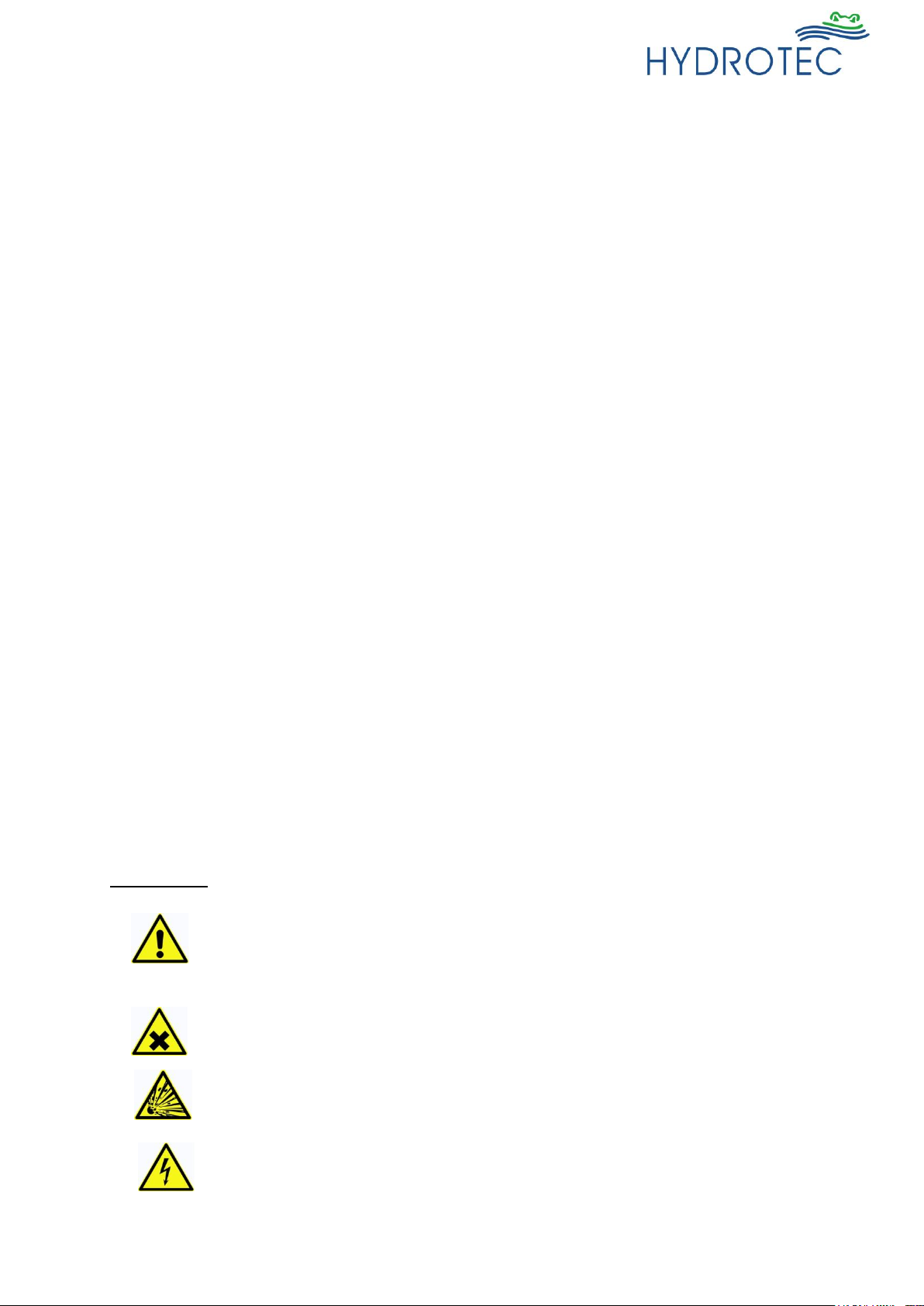
Warn signs:
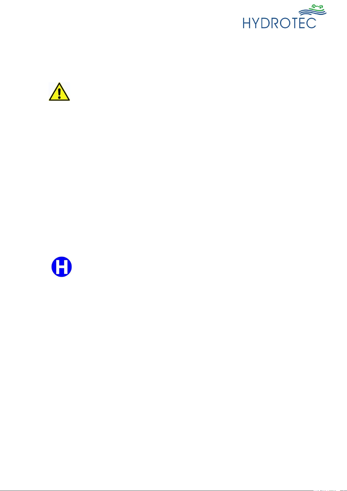
Caution!
Any negligent opperation may result in an extreme health hazard as well as
material damage!
Health hazardous or irritating substances!
Substances with an explosive risk!
Electrical voltage!
I-6/103
Last change 04/2016 E-P – AL/TW/PW | Subject to technical modifications
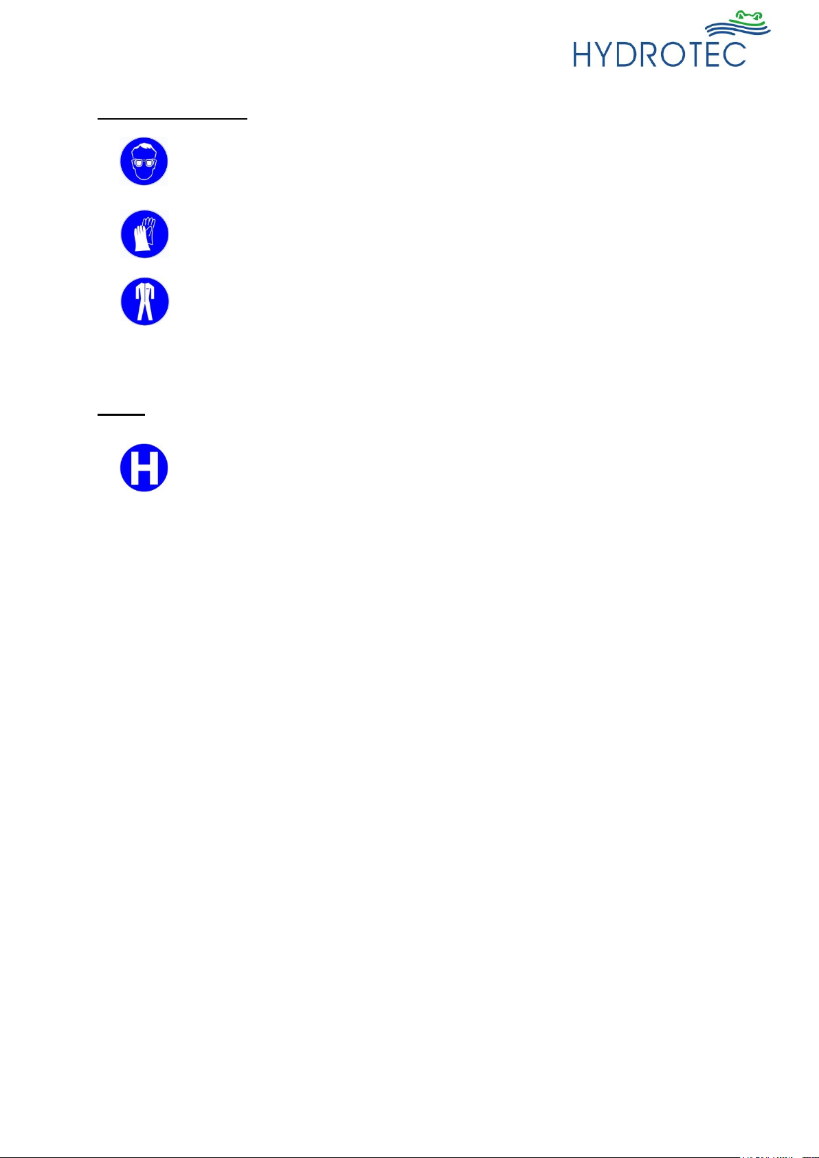
Minimum PPE signs:
Wear eye protection!
Wear protection gloves!
Wear protective clothing!
Notes:
Tips and additional information to make work easier for efficient operation.
2.2 Operator’s duty of care
The system is constructed and manufactured with respect to and in consideration of all current
standards as well as further technical specifications, and has the latest state-of-the-art technology,
allowing for maximum safety under all operating conditions.
System safety in operation can only be assured if all necessary measures are taken beforehand. It is
part of the operator’s diligence to plan and monitor such measures and implement them with due care.
The operator must ensure that:
- The system is used in accordance with the specified purpose.
- The system is maintained in a serviceable condition, with the safety facilities being monitored
for correct function at regular intervals.
- The operation and maintenance manual is always in a legible condition and available next to
the unit.
- The operation, maintenance and repair work is carried out by qualified and authorised
personnel only.
All safety and warning information attached to the system must not be removed and must be kept in
a legible condition.
I-7/103
Last change 04/2016 E-P – AL/TW/PW | Subject to technical modifications
2.3 Appropriate use
Important! Any other use of the system, other than described, is deemed to be not in
accordance with the specification.
The manufacturer / supplier will not accept any liability resulting from the
improper use of the system. Such risks are borne by the operator.
All regulations and instructions in the operating and maintenance manual and
applicable local regulations must be strictly adhered to.
Any malfunctions must be reported and corrected immediately.
2.4 Basic safety measures
Prior to starting the system you must guarantee that:
- No-one can suffer injury due to the system operation.
- All safety facilities are in a perfectly usable condition.
The system must be operated in perfect condition only. Any faults/errors should be reported
immediately to the responsible person.
In order to avoid flooding of site, a drainage and/or leak detection system with an
alarm should be provided.
I-8/103
Last change 04/2016 E-P – AL/TW/PW | Subject to technical modifications
Maintenance, repair and electrical work
- All inspection and maintenance intervals specified in the operation and maintenance
manual must be adhered to.
- Prior to any work, the system must be disconnected from mains.
- The system is to be de-pressurized and shall be protected from accidental re-start.
- Only suitable and correctly functioning load-supporting devices shall be used when
replacing heavy components or system elements.
- Hose lines shall be replaced regularly (preventive maintenance) even if no damage is visible.
- Prior to any work on electrical components the system must be disconnected from the mains.
- Electrical equipment must be checked in regular intervals.
- Any possible loose connections must be re-secured and damaged electric cabling replaced
immediately.
- Casings of electric equipment and system components must never be cleaned with a water
hose (spray).
- Electrical components must never be touched with wet hands.
- Whilst working on the equipment suitable protective clothing shall be worn (e.g. when
handling with liquids such as acids and bases/alkalis).
Start-up after maintenance and repair work
- Check all screw connections for tight fit.
- Ensure that any components removed beforehand (e.g. tank lid, screen or filter) are installed
and restored to their correct operational position.
- All materials, tools and other appliances which were necessary for maintenance and repair
work are removed from the working area of the system.
- Any spills to be cleaned up safely.
- Ensure that all safety equipment is in perfect condition.
Regulations in respect to environmental protection
When working on and with the system, all legal regulations in respect to waste minimisation and proper
disposal (if appropriate) must be understood and followed.
The elements listed below must not contaminate the soil or enter the drainage system during
installation, maintenance or repair work:
- Grease and lubrication oils
- Hydraulic oils
- Cooling agents
- Acids and alkalis (bases)
- Cleaning materials containing solvents
These substances must be stored, transported and collected in suitable tanks and disposed of
in accordance with the applicable regulations.

I-9/103
Last change 04/2016 E-P – AL/TW/PW | Subject to technical modifications
2.5 Risks in the event of safety instructions being disregarded
The consequences of disregarding safety instructions can be dangerous to the
system, material and personnel. This will also invalidate any warranty claims.
We shall not accept liability for water damage caused due to disregard of the safety
instructions!
2.6 Operational and Ancillary Materials
Safety datasheets:
Safety datasheets for operational materials required for the operation can be made available on
request.
3. Special safety information for the chlorine dioxide unit
Operator
- On request, the plant operator shall provide a risk assessment for chemical storage.
- All nameplates and information supplied by the manufacturer with the plant must be attached and
clearly visible at plant location.
- Only instructed and trained staff shall operate the plant.
- The correct protective clothing (face mask, protective gloves, safety rubber boots and protective
apron) shall be made available to the operators.
- The plant should be only be installed by qualified professionals!
A full re-commissioning of the plant should be undertaken if the unit has had extended downtime!
The maintenance and servicing must be followed at the recommended intervals!
- The room where the chlorine dioxide is installed should be fireproofed from connecting rooms.

I-10/103
Last change 04/2016 E-P – AL/TW/PW | Subject to technical modifications
Special risk
- Chlorine dioxide spills should not be removed with tissues!
There is a self-ignition risk with dry tissue and chemical residue!
- Overpressure can be applied to the plant components!
Risk of injury and material damage from flowing water and sudden pressure
release of components! All pressure pipes must be inspected at regular
intervals!
- The use of chemicals with an excessive concentration or mistaking of chemical
tubs or intake lancets can result in an explosion risk – Check safety data sheets,
the unit is also colour coded to help with identification of chemical location!
- Contact with chlorine dioxide, sodium chloride solution or hydrochloric acid
may cause a chemical burn!
Affected skin and clothing must immediately and carefully be washed with
water!
- Risk of chemical irritancy of eyes, respiratory organs and skin by breathing in
chlorine dioxide, sodium chloride solution and hydrochloric acid!
Protective clothing (as per accident prevention rules) must be worn whilst the
chemical tubs are replaced!
- You should not carry out safety-technical or functional modification!
Consequence may cause material damage or injury to persons!
- It is forbidden to smoke and/or handle with open fire in rooms where
sodium chloride and familiar solutions are operated with and/or stored!
Safety and control equipment of plant
- All plant components suited to produce chlorine dioxide are housed in a common
lockable housing.
- The reactor tank is situated in a separate reactor enclosure inside the unit.
- An individual chemical bund is provided for the sodium chloride solution and the
hydrochloric acid.
- The chemical dosing pumps are each equipped with pressure holding valve.
- The chlorine dioxide content is controlled continually and is evaluated and monitored
by the control unit.
- The chlorine dioxide feed in the ring water line of the plant is secured by non-return
valves to prevent backflow.
- A static mixer installed in the ring water line (outlet side) ensures mixing of the water
with the chlorine dioxide.
- The plant can be actuated by an external contact water meter (For safety reasons it
must be a ratio of K:1 or K:10).
- The control system will show an alarm if the high level chemical limit is reached.

I-11/103
Last change 04/2016 E-P – AL/TW/PW | Subject to technical modifications
4. Warranty
The warranty period for the system is 12 months, calculated from either the date of commissioning by
Hydrotec (UK) Ltd, 15 months from the date of supply or in the event that commissioning is not included
with the supply agreement, whichever is the shorter. The plant must be operated and maintained in
accordance with Hydrotec (UK) Ltd’s requirements. It is recommended that a service contract is taken
out for the unit.
Claims under warranty will only be accepted under the terms of our General Conditions of Sale and
Supply subject to the following conditions:
- The system is used and operated in accordance with information and instructions in the
operation and maintenance manual.
- The system is treated properly.
- Repair work is to be carried out exclusively by authorised specialists.
- Original spare parts by Hydrotec (UK) Ltd shall be used exclusively.
- No modifications are carried out on the system by users themselves.
- The stipulated operation parameters (pressures, flow volume) are maintained and a water
temperature of 30°C is not exceeded.
- Start-up of the system has been carried out by our service personnel.
- A service every 6 months is carried out by Hydrotec service personnel.
- Excluded from warranty claim are all parts subject to wear and tear such as:
All moving parts, motors, seals, membranes, filters etc.
- Warranty claims cannot be accepted in cases of:
- Operation and installation errors
- 3rd party maintenance
- Deliberate damage or negligent handling
- Any unauthorised modifications are not permitted for safety reasons. Original spare parts
and accessories are specifically designed for the HydroDOS®.
Only genuine spare parts are to be used!
- Important information for any queries and spare parts orders:
- Plant type (model number)
- Serial number
- Date of manufacture
- Description/Photo of problem/part
I-12/103
Last change 04/2016 E-P – AL/TW/PW | Subject to technical modifications
Chapter II - Transport and Storage – Chlorine Dioxide Unit
The shipping weight (see table “Technical Data” in chapter III) is the net weight of the total plant.
The plant shall be shipped empty!
Appropriate measures must be taken to avoid any damage during transport.
The entire delivery must be checked for completeness and possible transport damage immediately
upon receipt at the warehouse/site.
Caution! Damaged plants shall not be installed.
The system must be protected from frost during transport and storage.
The maximum ambient temperature of 36°C must not be exceeded in
storage.
The chemicals hydrochloric acid and sodium chlorite shipped together with the plant
must be stored separatly during transport. It is safety critical that these do not get in
touch.
The chemicals must be secured accordingly and marked.
Storage of chemicals shall be in specially marked original plastic tubs!
The chemical components shall not be stored next to:
- any grease
- easily inflammable components
- acids
- salts
Chemicals used:
Hydrochloric acid (HCl) 9 %
Sodium chloride (NaClO2) 7.5 %
Purity of chemicals according to DIN EN 938 or DIN EN 939, i.e. suited for drinking
water treatment.
Empty and full chemical tubs must be stored closed and exclusively at sites suited for
storage as per valid accident prevention regulation!

I-13/103
Last change 04/2016 E-P – AL/TW/PW | Subject to technical modifications
Chapter III – System description / Technical Data
Page
1. System description 2
1.1 General 2
1.2 Function 4
1.3 Water pressure 5
1.4 Demand on water connection 5
2. Technical Data 6
2.1 Technical Data – Chlorine dioxide system 6
2.2 Installation schematic 7
3. Scope of supply 8
3.1 Components 8
- Installation cabinet 8
- Reactor cabinet 9
- Chlorine dioxide reactor 9
- Dosing pumps 9
- Chemical collection tubs 10
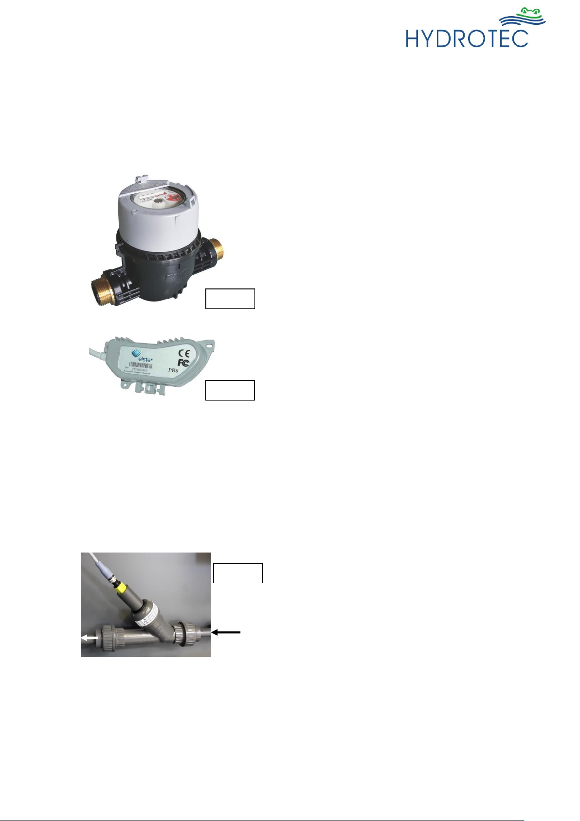
- Polymer piston water meter with communication module 10
- Pressure measuring / control 10
- Chlorine dioxide measuring 10
- Chlorine dioxide control 11
- Switchboard 11
- Fittings 11
- Pipeline 11
3.2 Accessories 12
- Hydrochloric acid 12
- Sodium chlorite solution 12
- Neutralising agent 12
- Protective equipment 12
I-14/103
Last change 04/2016 E-P – AL/TW/PW | Subject to technical modifications
1. System description
1.1 General
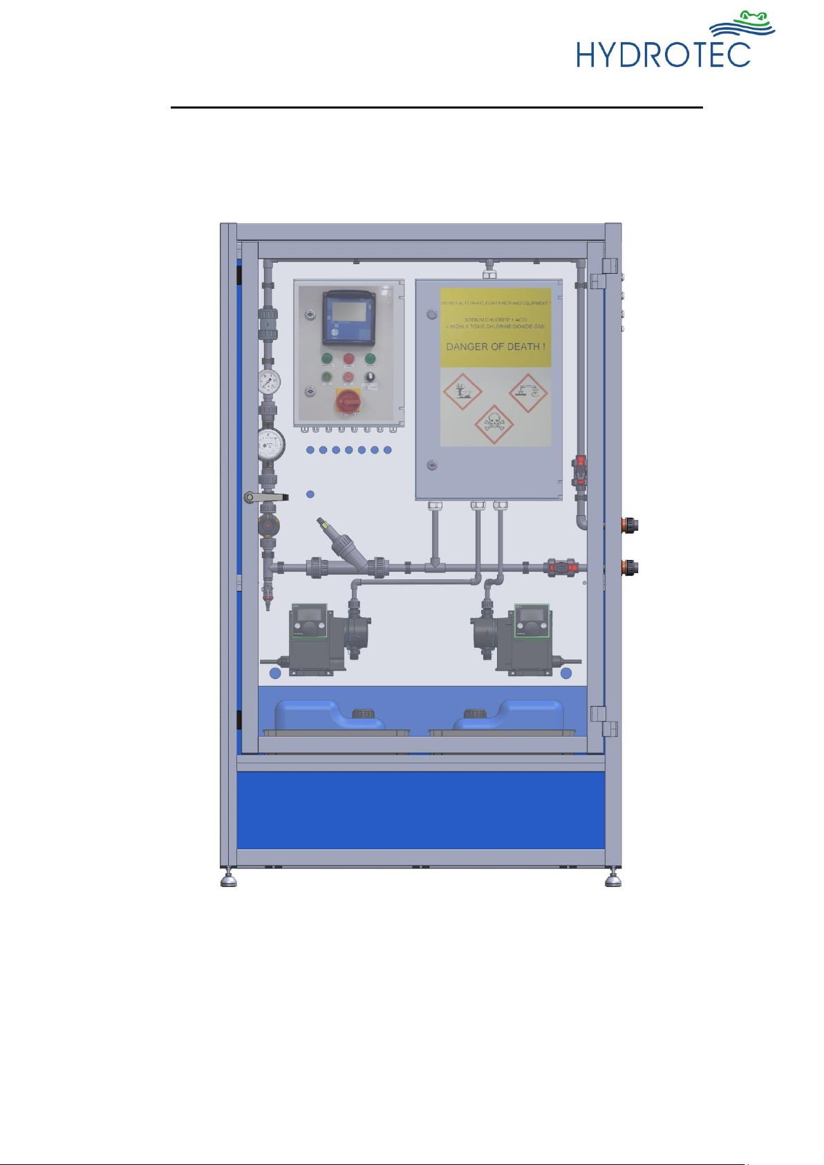
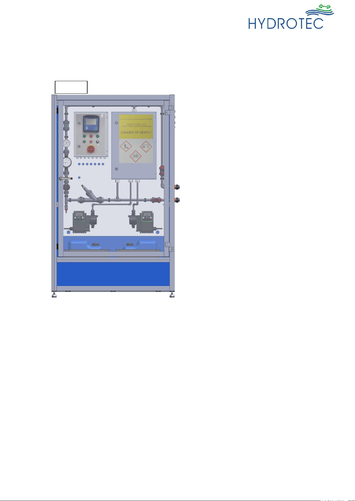
The HydroDOS® system is designed as a cabinet
system and is used for the production of chlorine
dioxide.
A chlorine dioxide solution is automatically
produced from the chemicals hydrochloric acid
(9%) and sodium chlorite (7.5%).
Both reactants are mixed in a reactor chamber so
that a solution with a maximum concentration of
20 g/l is available for dosing. The chlorine dioxide
concentration is then substantially diluted in the
by-pass-path.
Coming from the consumer feed/cold water
storage tank, a part flow volume is fed to the
chlorine dioxide system, dosing agent added and
fed again in the consumer feed or water storage
tank.
Corresponding measuring equipment (for
chlorine dioxide and flow volume) is provided to
control dosing.
Due to the concept and control of the plant, all
operation states guarantee a secure operation.
Application:
- Removal of odorous and flavouring
substances.
- Inhibition of algae growth in open storage
systems.
- Slime combat in cooling systems and open
circuits.
- Disinfection of filter and softener systems.
- Disinfection of water containing ammonia
traces possible.
- Degeneration of biofilms in pipe systems.
- Legionella combat and stabilizing of
contaminated systems.
- Disinfection within a broad pH-value range.
Ill. 1

I-15/103
Last change 04/2016 E-P – AL/TW/PW | Subject to technical modifications
Process
The chlorine dioxide disinfection process uses the strong reactivity of the chlorine dioxide gas,
whereby the gas can kill all types of germs and virus almost totally. Chlorine dioxide is more efficient
than disinfection by means of chlorine. Since chlorine dioxide is a gaseous and instable material,
production for stock is not possible. It is rather necessary to produce chlorine dioxide in a controlled
way in situ from the chemicals sodium chlorite and hydrochloric acid.
The chlorine dioxide volume produced is always dependent on the actual demand. The process is
actuated by an external water meter that releases the operation processes of the plant via the plant
control (The pulsing ratio of the water meter must be K=1 or K=10 only). The control recognizes
the demand and the dosing of reactants into the reactor is initiated, whereby there is always a small
surplus of hydrochloric acid in order that sodium chlorite reacts totally and does not penetrate the
drinking water.
4HCl + 5NaClO
2
→ 4ClO2 + 5NaCl + 2H2O
Hydrochloric acid Sodium chlorite Chlorine dioxide Salt Water
The above reaction formula shows that apart from chlorine dioxide, water and salt is produced in the
reaction.
The below chemicals are used for the production of chlorine dioxide:
➢ Hydrochloric acid (HCl) 9 %
➢ Sodium chlorite (NaClO2) 7.5%
The purity of chemicals is according to DIN EN 939 or DIN EN 938, i.e. suitable for drinking water.
Required for the production of 1 kg chlorine dioxide:
- 25 ltrs. sodium chlorite solution 7.5%
- 25 ltrs. hydrochloric acid 9%
The product from the reaction is fed to part of the drinking water flow, mixed and diluted.
Since the plant was designed and constructed according to legal rules (limit value 0.5 mg/l) the taste
of the water will not be affected at this low concentration.
I-16/103
Last change 04/2016 E-P – AL/TW/PW | Subject to technical modifications
1.2 Function
HydroDOS® system is suited for the production of chlorine dioxide situated in a plant cabinet with a
transparent door for visual control of plant.
All of the plant components are installed on a back plate.
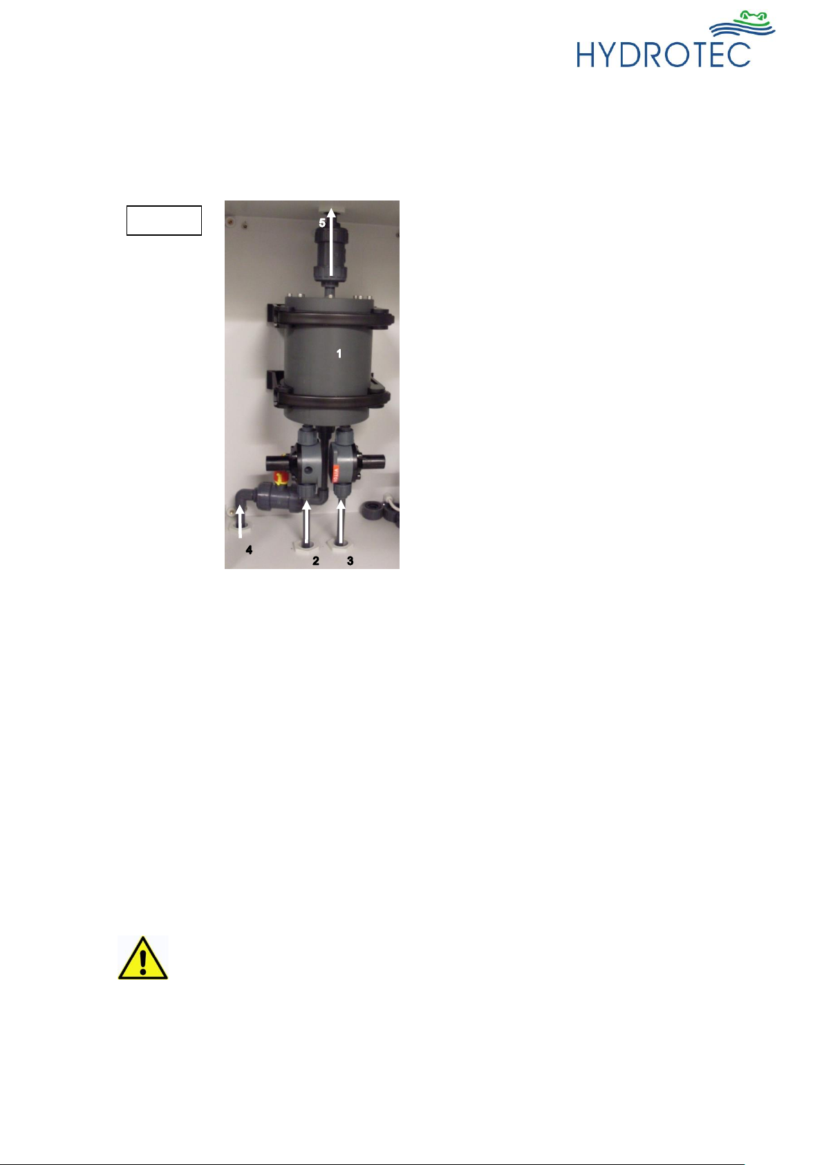
The chlorine dioxide is produced in the reactor
vessel that is housed in a separate reactor
cabnet in the plant.
Chemicals are fed to the reaction chamber by
dosing pumps in the corresponding volume.
➢ Hydrochloric acid (HCl) 9 %
➢ Sodium chlorite (NaClO2) 7.5 %
1 = Reactor vessel
2 = Dosing of sodium chlorite
3 = Dosing of hydrochloric acid
4 = Water feed (only for commissioning)
THE ISOLATION VALVE MUST NOT TO BE
OPENED – CAN ONLY BE OPENED BY
AUTHORISED PERSONNEL – RISK OF
SERIOUS HARM.
5 = Chlorine dioxide to feed in the test loop pipe
The test loop pipe is connected to the transfer pipes (input/output) outside the plant cabinet. The
pipe is designed as a ring line inside the plant cabinet and is equipped with corresponding stop and
safety fittings.
The measuring instruments below are installed in the pipe work to control the plant:
➢ Chlorine dioxide measuring
➢ Flow volume measuring (to control the volume flow)
➢ Pressure control (to monitor the pressure inside the test loop pipe)
➢ In-line static mixer (for quick mixing of chlorine dioxide with drinking water in the ring line)
The reactants are taken from the chemical tubs by means of the intake lances of the respective
dosing pump and fed into the reactor vessel. The chemical tubs are provided in separate collection
tanks beneath the unit inside the plant cabinet.
Caution! When replacing chemical tubs you must check that:
- The tubs are placed in the correct collection tank!
- The correct intake lance for the corresponding chemical is used!
- The chemical feed is connected to the corresponding pump!
Information and colour codes on the chemical tubs, dosing pumps and intake
lances must be checked!
If an incorrect chemical, tub etc. is used it may result in an explosion risk and
extensive material damage or injury to persons!
Ill. 2

I-17/103
Last change 04/2016 E-P – AL/TW/PW | Subject to technical modifications
1.3 Water pressure
In order to guarantee optimum and economic operation of the system, the water pressure should be
adjusted to between 2.0 – 6.0 bar.
The water pressure should not fall below 2.0 bar in order not to impair the functional performance of
the system.
Regular maintenance avoids the increase of pressure loss and guarantees correct system operation.
The water pressure must not exceed 6 bar (static pressure), doing so may pose a safety risk and
cause operational problems. It is recommended that a pressure reducing valve be fitted upstream of
the chlorine dioxide production system.
The chlorine dioxide production system must be installed below the level of the dosing position.
1.4 Demand to the water supply
The below must be regarded for the start-up of the chlorine dioxide production system:
➢ The sample loop flow to the chlorine dioxide production system must guarantee a sufficient
flow.
➢ No particles must be included in the drinking water.
➢ No hydraulic shocks must be evident in the test loop flow.
I-18/103
Last change 04/2016 E-P – AL/TW/PW | Subject to technical modifications
2. Technical Data
2.1 Technical Data – Chlorine dioxide production system
Type HYDRO DOS® HD 550G
Water feed (input) DN 15
Water feed (output)
DN 15
Discharge connection
¼” (hose connection)
Mains electrical connection
230 V / 50 Hz AC
Min./max. power input
VA
20 / 500
Protection type IP 54
Operational pressure
bar
2 – 6
Water temperature
°C
5 – 30
Ambient temperature
°C
> 10 – 40 (no direct sun radiation)
Relative humidity
70 % not condensing
Performance data
Chlorine dioxide preparation efficiency
g/h
215
Max. water flow
l/h
300
Reactor vessel volume
Litres
0.92
Concentration chlorine dioxide solution
Reactor output: 20 g ClO2/l
After dilution: 0.1 – 2.5 g ClO2/l
Chemicals / consumption
Hydrochloric acid (9 %) DIN EN 939
Consumption max.:
l/h
6
Sodium chlorite (7.5 %) DIN 938
Consumption max.:
l/h
6
Dosing pumps
Efficiency
l/h
6
Max. pressure
bar
10
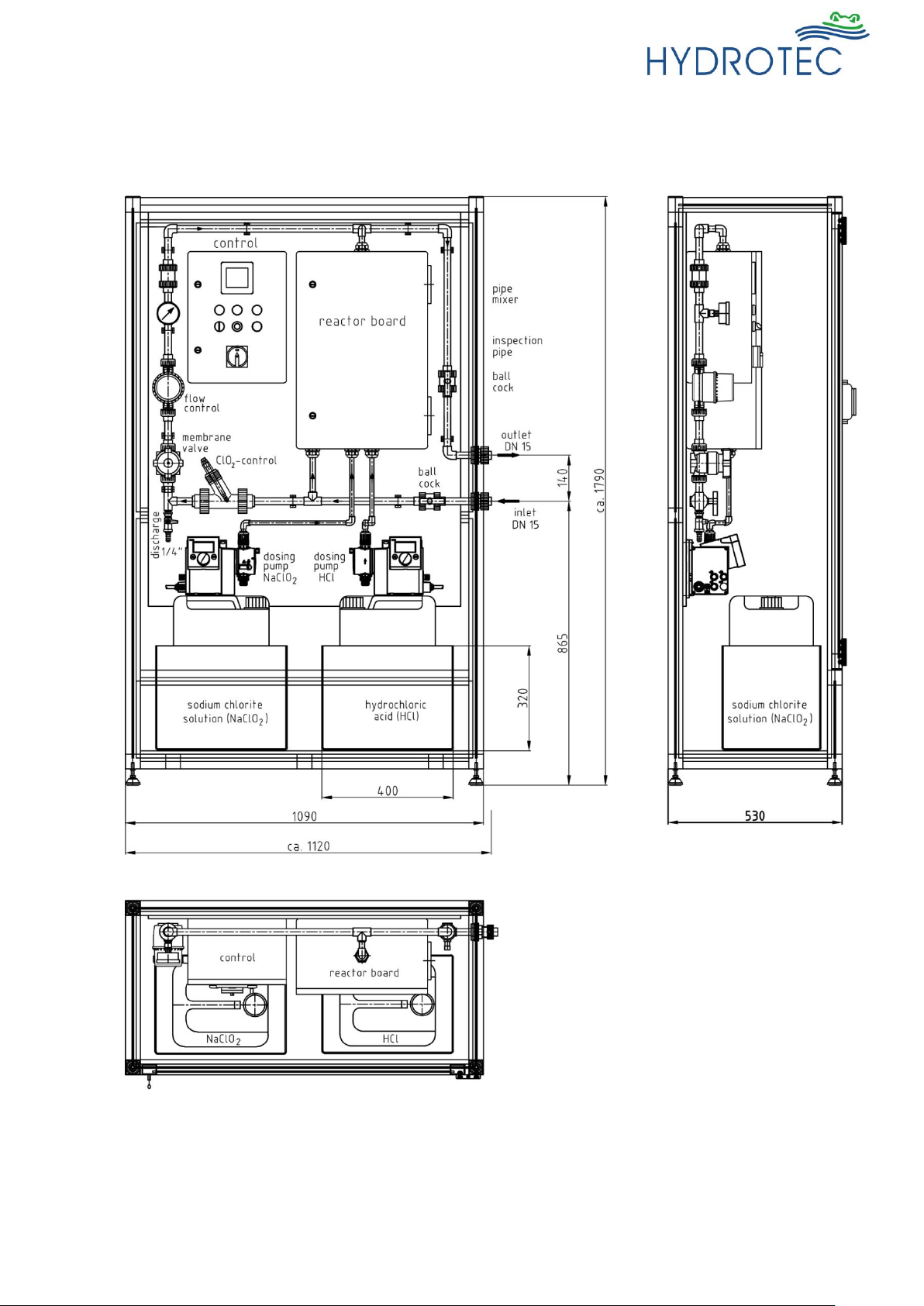
Dimensions and weight
Height ca.
mm
1790
Width ca.
mm
1120
Depth ca.
mm
530
Weight ca.
kg
120
I-19/103
Last change 04/2016 E-P – AL/TW/PW | Subject to technical modifications
2.2 Installation schematics
I-20/103
Last change 04/2016 E-P – AL/TW/PW | Subject to technical modifications
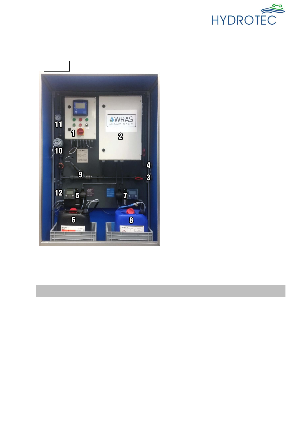
3. Scope of supply
3.1 Components
1 = Control box
2 = Reactor cabinet
3 = Plant input (DN 15)
4 = Plant output (DN 15)
5 = Dosing pump with intake lance for sodium
chlorite
6 = Tub for sodium chlorite (NaClO2 - 7.5 %),
positioned in a collection tank
7 = Dosing pump with intake lance for
hydrochloric acid
8 = Tub for hydrochloric acid (HCl - 9%),
positioned in a collection tank
9 = Chlorine dioxide measuring /control
10 = Flow volume measuring / control
11 = Pressure control
12 = Discharge
Equipment
Description
Installation board
Suited to accommodate the HydroDOS® system for the
production of chlorine dioxide, consisting of:
- Sectional frame of anodized aluminium profiles
- PVC side walls and assembly plate
- Lockable door with transparent plastic inspection glass
- Height-adjustable feet
Dimensions: Height 1790 mm
Width 1090 mm
Depth 530 mm
Ill. 3
I-21/103
Last change 04/2016 E-P – AL/TW/PW | Subject to technical modifications
Reactor cabinet
Suited for the installation of the chlorine dioxide reactor;
lockable, protection type IP 66
Material: Polyester
Dimensions: Width 400 mm
Height 600 mm
Depth 230 mm
Quantity: 1
Including ventilation unit for odour neutralizing, carbon
fibre filter mats at input and output.
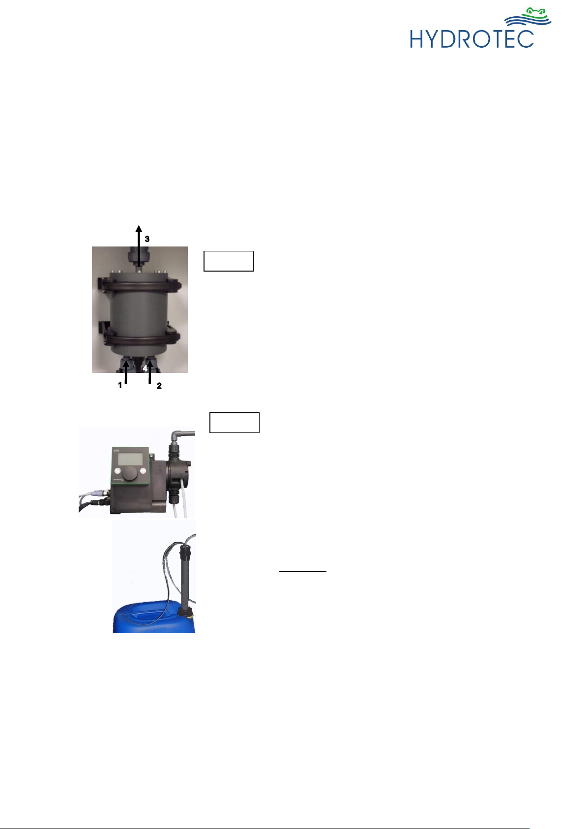
Chlorine dioxide reactor
Reaction chamber used for the production of chlorine
dioxide from the chemicals hydrochloric acid and sodium
chlorite solution.
Material: PVC-U
Reactor volume: 0.92 litres
Dimensions: Outer diameter 140 mm
Height 190 mm
Quantity: 1
Including connections for:
- hydrochloric acid (1)
- sodium chlorite (2)
- chlorine dioxide (3)
- water used for start-up of system (4)
Dosing pumps
Suited for dosing the reactant chemicals into the reactor
tub:
- hydrochloric acid 9 %
- sodium chlorite solution 7.5 %
Digital membrane dosing pump with step control
technology type SMT 6.0 B1
Efficiency: 6.0 l/h against 10 bar
Mains electrical connection: 230 V / 50 Hz
Max. power input P1: 14 Watt
Materials:
Dosing head PVC
valve ball ceramic
Gasket EPDM
Connections PVC
Quantity: 2
2 intake lances to be installed in the chemical tubs
Material: PVC / Glass
Connection: PE – 4/6
2 pressure maintain valves and non-return stop into the
chemical feed to the reactor tub
Material: PVC / FKM
Intake lancet
Chemical tub
Ill. 4
Ill. 5
Dosing pump
Wall mount
I-22/103
Last change 04/2016 E-P – AL/TW/PW | Subject to technical modifications
Chemical collection tanks
2 Euro tanks used for separate installation of chemical
tubs during operation.
Material: PP
Dimensions (L x W x H): 400 x 300 x 320 mm
Polymer piston water meter with
communication module
Used for monitoring of flow rate in the drinking water ring
line.
The communication module is sending a signal to the
controller so that the PLC control can monitor and
display the flow rate.
Design: Piston water meter with impulse
module
Flow volume: 2.5 m³/h
Connection: G ¾” (AG – external thread)
Impulse frequency: 1 litre / impulse
Quantity: 1
Weight: 0.57 kg
Pressure measuring / control
Suited to control the pressure in the drinking water ring
line.
Design: stainless steel pressure gauge
Nom. size: 63 mm
Display: 0 – 16 bar
Connection: G ¼” (AG – external thread)
Quantity: 1
Chlorine dioxide measuring
1 flow fitting incl. sensor suited for chlorine dioxide
measuring; installation in drinking water ring line.
Material (fitting): PVC
Max. operation pressure: 16 bar
Connection: DN 25
Sensor design: one-rod sensor (potentiostatic doublegold-sensor) incl. integrated shielded connection cable.
Ill. 8
III. 6
III. 7
To control
Flow direction
Flow fitting
ClO2sensor

I-23/103
Last change 04/2016 E-P – AL/TW/PW | Subject to technical modifications
Chlorine dioxide control
Measuring control unit (Neon controller) for monitoring of
chlorine dioxide concentration in water supply, mounted
in the control cabinet of the system.
Dimensions: 144x144x83 mm
Material: ABS
Weight: 0.6 kg
Protection class: IP 54
Power consumption: 10 VA
Quantity: 1
Control cabinet
Suited for the installation of the control unit to monitor the
plant parameters and of the measuring and regulation
device to control the chlorine dioxide content; lockable
design, protection type IP 66, including assembly plate
of sheet steel.
Material: Polyester
Dimensions: Width 300 mm
Height 400 mm
Depth 200 mm
Quantity: 1
Fittings
The below fittings are required for the operation of the
chlorine dioxide production system:
- membrane valve (incl. lockable hand-wheel) for
flow volume regulation of drinking water ring line
- ball valve for input / output of plant, flushing
connection reactor
- non-return valves in reactor output and in the
drinking water ring line to avoid hydraulic shocks
- discharge ball valve with hose connection for
water discharge for system discharge or
possibility of sampling.
Material: PVC
Nom. pressure: PN 10 and PN 16
Pipeline
Plant provided with pipe ready to connect
Material: PVC-U
Nom. pressure: PN 16
Ill. 9

I-24/103
Last change 04/2016 E-P – AL/TW/PW | Subject to technical modifications
3.2 Accessories
Hydrochloric acid (HCl)
Chemical used for the production of chlorine dioxide
Concentration: 9 % (purity as per DIN EN 939)
Tub volume: 25 litres
Sodium chlorite solution (NaClO2)
Chemical used for the production of chlorine dioxide
Concentration: 7.5 % (purity as per DIN EN 938)
Tub volume: 25 litres
Neutralising agent
Neutralising agent (DESULAN EX) for chlorine dioxide
solutions
Measuring instrument chlorine
dioxide
(for quick test)
Photometer chlorine dioxide
(calibration-comparison measuring)
Measuring range: 0.05 to 0.5 mg/l ClO
2
Measuring range: 0.05 to 0.5 mg/l ClO
2
Protective equipment
Protective accessories comprising:
- Gas mask
- Rubber protective gloves
- Rubber protective (safety) apron
- Protective glasses
- Rubber boots

I-25/103
Last change 04/2016 E-P – AL/TW/PW | Subject to technical modifications
Chapter IV – Installation and Assembly
Page
1. General information 2
2. Installation site 4
3. Pre-assembly 4
Control of shipment 4
Input and output lines 4
Other preparation 5
Use of chemicals 5
4. Hydraulic connections 5
Installation input / output 5
Wash and discharge connection 6
5. Electric connections 7
Mains connection 7
Control 7
External water meter 8
Volt-free contact 8
External circulation pump 8

I-26/103
Last change 04/2016 E-P – AL/TW/PW | Subject to technical modifications
1. General information
The HydroDOS® chlorine dioxide disinfection system has been designed to be housed in an enclosure.
The individual components are mounted to a plate and connected to each other.
The system shall be integrated and connection to the local installation.
➢ Connection of required pipe work is to be realized at inputs and outputs of unit.
➢ Control of plant parameters is by the control unit.
➢ The plant is controlled by an external local water meter. The pulsing ratio of the water meter
must be K=1 or K=10 only.
➢ A wash / flush connection is provided for discharge and plant wash.
➢ 2 separate collection tubs for chemicals are provided within the plant
Installation of plant shall be carried out by experts.
I-27/103
Last change 04/2016 E-P – AL/TW/PW | Subject to technical modifications
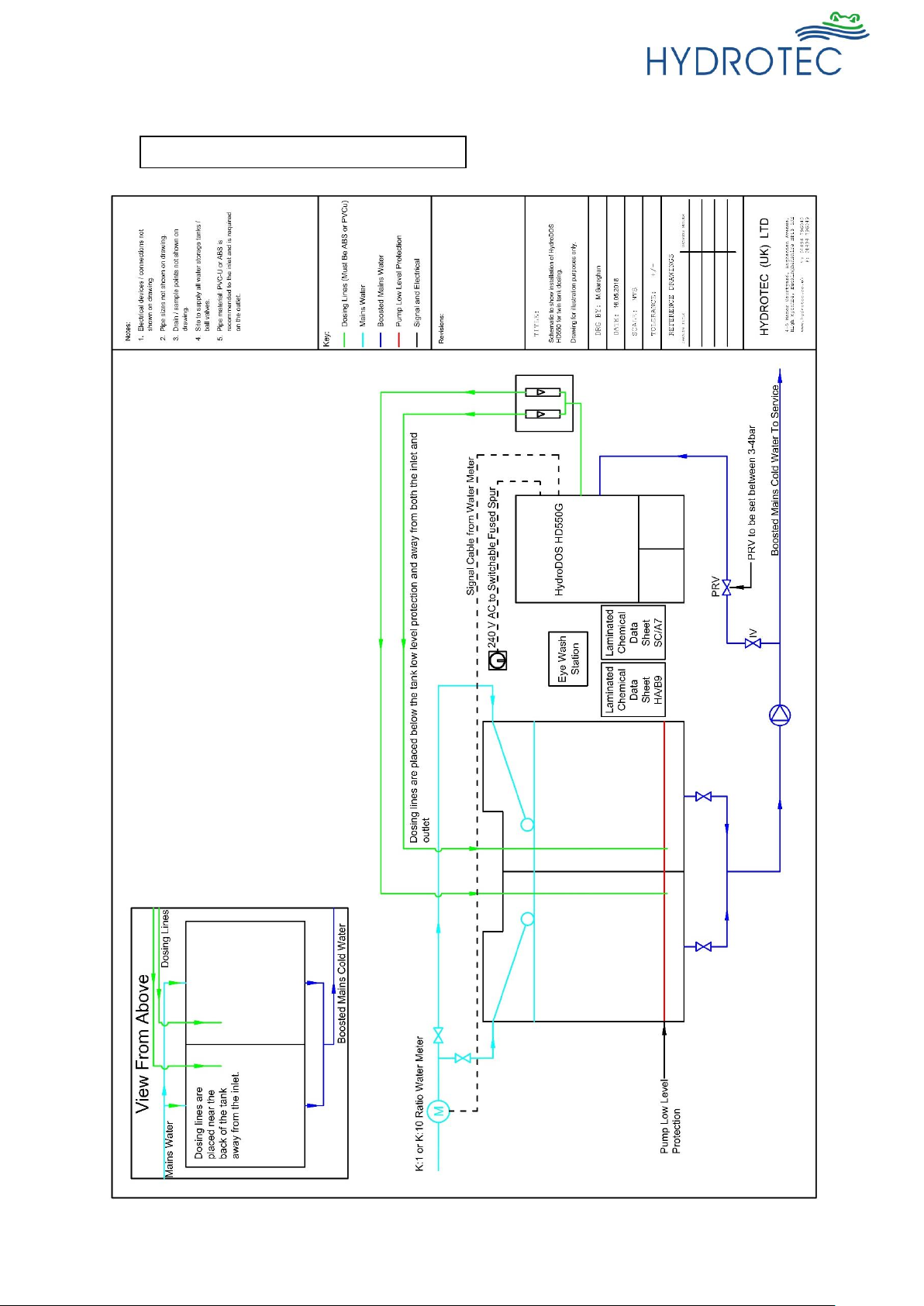
Installation example HydroDOS® Chlorine dioxide disinfection plant:
Ill. 1 Split Compartment Tank Installation
I-28/103
Last change 04/2016 E-P – AL/TW/PW | Subject to technical modifications
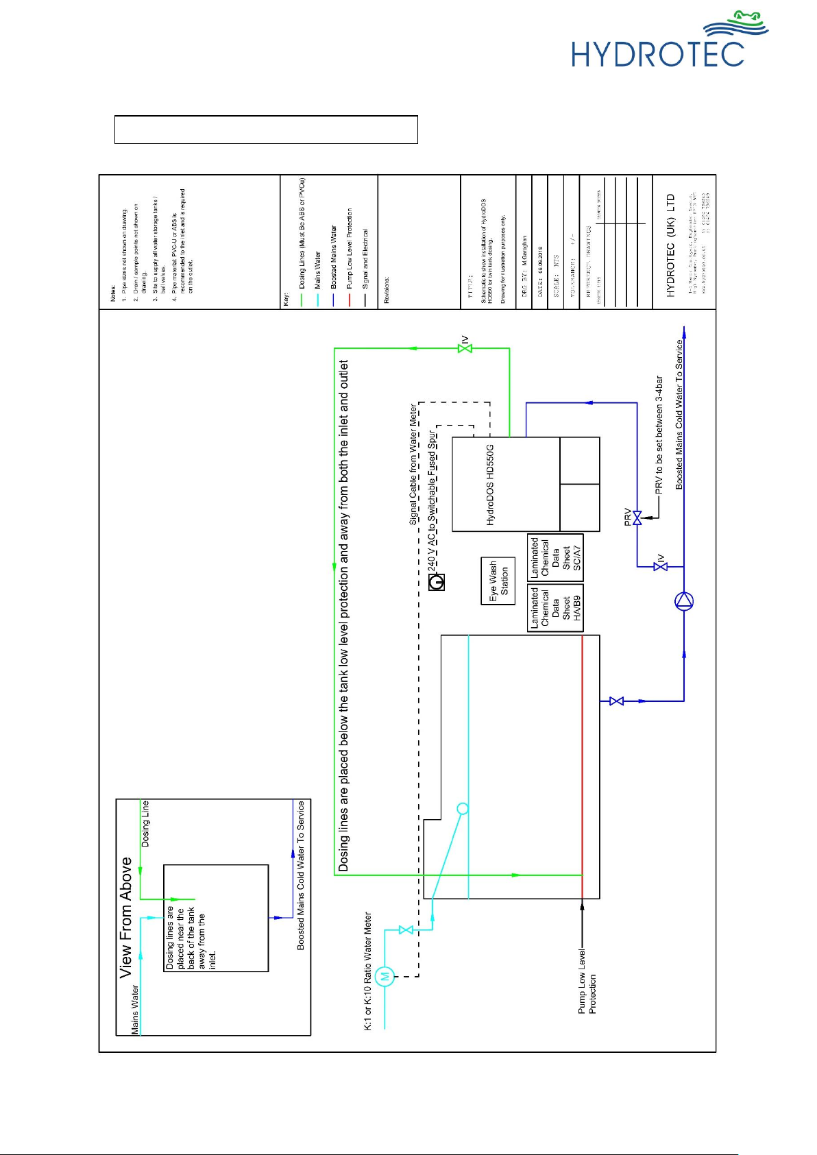
Ill. 2 Single Compartment Tank Installation

I-29/103
Last change 04/2016 E-P – AL/TW/PW | Subject to technical modifications
2. Installation site
The below must be understood and guaranteed during the installation of the chlorine dioxide
production system.
The minimum installation dimensions are shown in the dimensional sketch and table (see chapter III).
• Installation of chlorine dioxide disinfection system in a separate, frost-proof and well ventilated
room. If there are no louvered doors or the plantroom is classified as a confined space, then
some form of mechanical, forced ventilation system should be considered. Please bear in mind
that chlorine dioxide gas is heavier than air, so the air exhaust should be located nearer the
floor. The plant should never be installed outdoors.
The plant shall be protected from sunlight, dust and all kinds of vapor.
Room temperature shall not be less than 5°C and not exceed 40°C.
The installation site shall correspond to the local accident safety regulations!
• The installation surface shall be designed within an even surface tolerance as per DIN 18202
(2 mm at 0.1 m up to 15 mm at >15 m).
• A water discharge (bottom discharge) for the chemical residues shall be provided locally.
• Access to the connecting pipe must be guaranteed.
• A separate storage for empty and full chemical tubs shall be provided.
• A fireproof separation to adjacent rooms shall be provided.
• The installation site shall be secured by corresponding measures against unauthorized access
by third persons.
The installation site must not be used as a constant recreation room (max. 2 hours / day).
• An electric connection 230V, 50Hz shall be provided locally and permanent voltage
guaranteed.
• The operation manual must be available adjacent to the unit.
• Suitable personal protective clothing must be available at site suited to handle chemicals.
• All pipework from the unit must be ½” / 15mm and in uPVC plastic.The inlet however may be
installed in copper or uPVC,
• An eye wash station is mandatory and must be provided locally to the unit in a visible
location
• Laminated Material Safety Data Sheets displayed for the chemicals in use with the
system are mandatory.
I-30/103
Last change 04/2016 E-P – AL/TW/PW | Subject to technical modifications
3. Pre-assembly
Control of shipment
The delivery shall be checked for completeness and
possible transport damage prior to installation and
assembly.
Any issues must be recorded immediately.
Input and output pipe
Input and output pipes shall be provided to the unit in the
required positions.
Other preparation
- Pressure and temperature in the feed pipe must be
checked. If the pressure exceeds 6 bar there is a
requirement to install pressure reducing valve.
- Room temperature and humidity shall be checked.
- A local authorization for chemical storage should be
applied on request.
- Protective clothing shall be provided at installation site.
- Any warning and information plates included in the
delivery shall be attached and clearly visible.
Use of chemicals
Caution!
Only chemicals with the following
concentration must be used:
Hydrochloric Acid (HCL) 9 %
Sodium Chloride solution(NaClO2) 7.5%
The chemical tubs shall be stored in a separate room
and placed and inserted in the corresponding
collecting tubs and connected prior to
commissioning.
For more detailed information regarding the connection of
the tubs, dosing pumps, lancets and the replacement of
the chemical tubs see chapter VIII – commissioning.
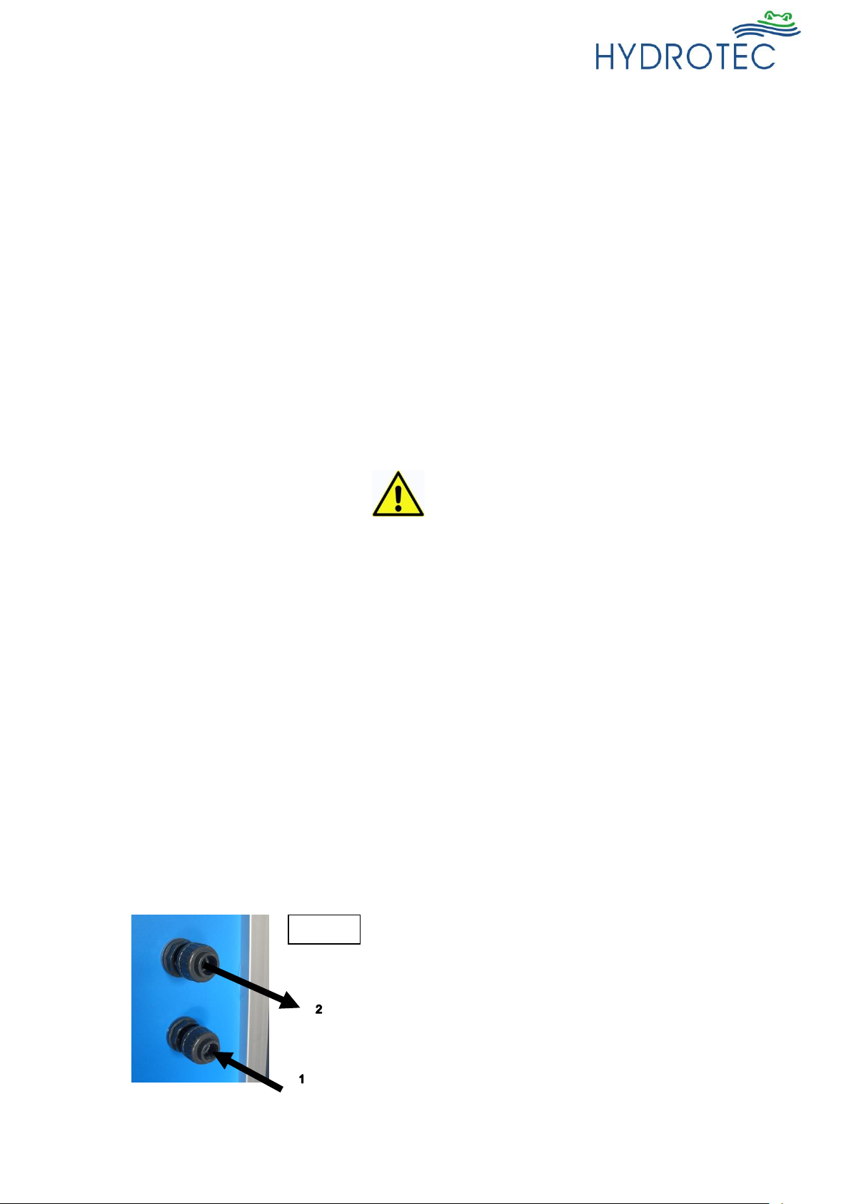
4. Hydraulic connections
Input / output
Connections for input and output of water are
provided at the outer right side of the board.
1 = Input (DN 15 – coupling)
2 = Output (DN 15 – coupling)
Ill. 4
 Loading...