

Hydro systems SuperDos 20, Model 0.3%, Model 0.3% PAA, Model 2.5%, Model 2.5 % WSP Operating Manual
...
20
Operating Manual•Mode D'Emploi
Bediehnungs Handbuch •Manual de Operación
Manual de operação • Manuale d'uso
Model 0.3%
Model 0.3% PAA
Model 2.5%
Model 2.5 % WSP
Model 5%
Model 10%
Fluid Flow Range:
Débit d'eau:
Durchussmenge:
Caudal de trabajo:
Vazão Operativa:
Velocità di usso:
0.04 gpm to 20 gpm
0,15 l/mn to 76 l/mn
Injection Range
Dosage:
Dosierung:
Dosicación:
Injeção:
Dosaggio:
0.025% to 10%
1:4000 to 1:10
Operating Pressure:
Pression:
Druck:
Presión operativa:
Pressão operativa:
Pressione operativa:
5 to 100* psi
0,34 to 6,9 bar
*Specications vary by model.
*Les données techniques varient
selon les modèles.
* Technische Daten sind je nach
Modell unterschiedlich.
* Características técnicas varían
según modelo.
* Características técnicas variam
conforme o modelo.
* Le speciche variano a seconda
del modello.
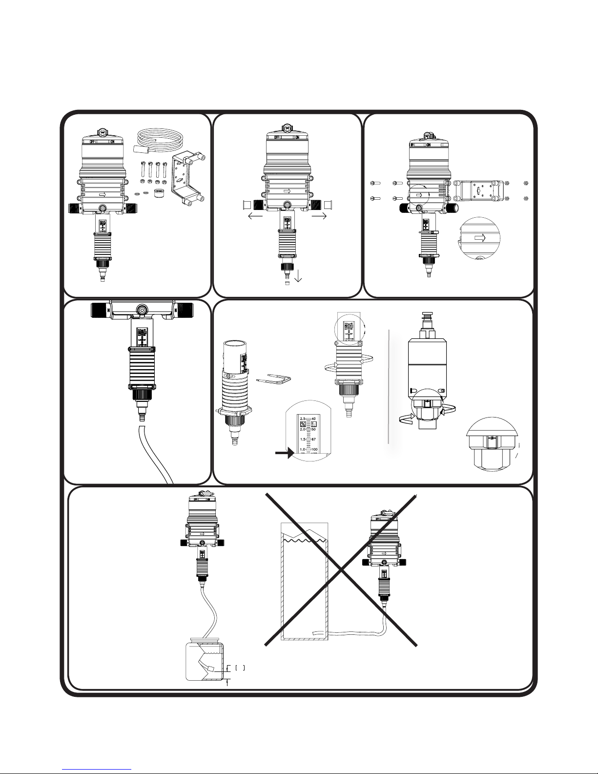
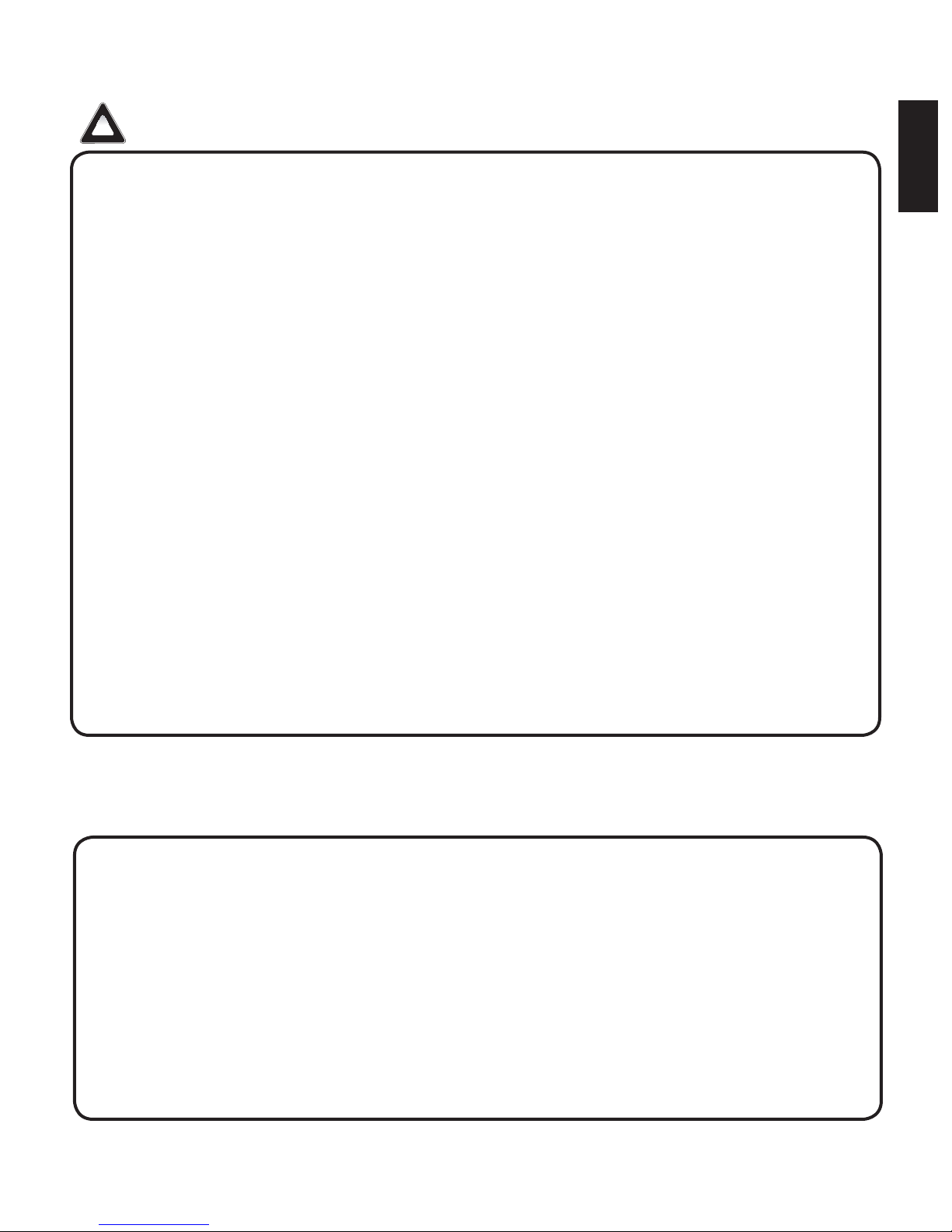
Quick Start Up
A
C
A
Puesta en marcha rápida
Démarrage Rapide
Schnell Antrieb
Inicialização rápida
A
A
↓
C
→
2
51
Part # 013825 Rev. G
English: 2

English....................................................3-21
Français................................................22-32
Deutsch.................................................33-43
Español.................................................44-54
English
Português.............................................55-65
Italiano..................................................66-83
Hydro Systems Company Ofces:
North America &
Global Headquarters:
Hydro Systems Company
3798 Round Bottom Road
Cincinnati, OH 45244
Phone: 513-271-8800
Fax: 513-271-0160
Toll Free: 800-543-7184
Asia Pacic:
Hydro Systems Asia Pacic
Unit A
1 Kelham Place
Glendenning, NSW 2761
Australia
Phone: 612-9625-8122
Fax: 612-9625-8177
Europe, Middle East,
Africa, & India
Hydro Systems Europe
Unit 3, The Sterling Centre,
Eastern Road
Bracknell, Berkshire
RG12 2PW
Europe
Phone: +44 1344 488880
Fax: +44 1344 488879
South America:
Hydro Systems South America
Rua Mogiana, 172,
Chacarras Reunidas,
Sao Jose Dos Campos,
Brasil
Phone: +55-12-3201-7707
Fax: +55-12-3201-7739
English: 3
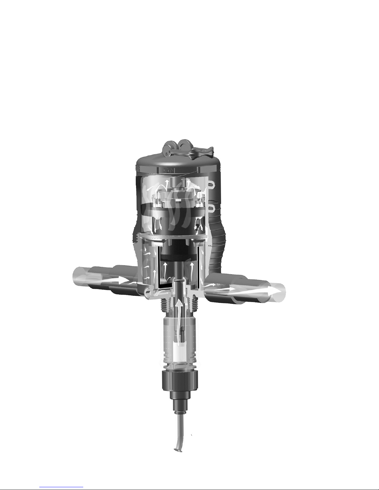
Operating Principle
Accurate and Reliable
Installed directly in the uid supply line, the injector operates without electricity, using uid (water)
pressure as the power source. The uid drives the injector, which pulls the required percentage of
concentrate directly from the chemical solution container. Inside the Hydro Systems patented mixing
chamber, the concentrate is mixed with the uid, and the uid pressure forces the mixed solution
downstream. The amount of concentrate will be directly proportional to the volume of uid entering
the injector, regardless of variations in ow or pressure.
Chemical does not
→
come in contact
with the motor.
→
Fluid ow drives
motor piston.
*MiniDos model shown, example only.
SuperDos 20 is not equipped with on/
off lever.
Chemical is mixed
→
in the patented
mixing chamber.
→
Blended solution
English: 4
Intake from chemical
→
container

English
Contents
Operating Principle ...................................................................................................................... 4
Package Contents ........................................................................................................................ 6
Specications .............................................................................................................................. 6
Safety Precautions ....................................................................................................................... 7
Warranty Compliance ................................................................................................................... 7
General Tips ................................................................................................................................7
Operations ...................................................................................................................................8
Installation and Start-up .............................................................................................................. 9
Suggested Installation Diagram ................................................................................................... 9
Maintenance ............................................................................................................................. 10
Remote Injecting ........................................................................................................................ 10
Routine Maintenance Instructions .............................................................................................. 11
0.3%, 2.5%, 5% ........................................................................................................................ 11
Routine Maintenance Instructions - 10% .................................................................................... 12
Troubleshooting ......................................................................................................................... 13
Injector Repair Parts .................................................................................................................14
Lower end & wear parts kits 0.3% PAA(Rotating): .......................................................................15
Lower end & wear parts kits 0.3% (Rotating): ............................................................................ 16
Lower end injector & wear parts kits 2.5%: ................................................................................17
Lower end injector & wear parts kits 2.5% WSP: ........................................................................18
Lower end injector & wear parts kits 5%: ...................................................................................19
Lower end injector & wear parts kits 10%: ................................................................................. 20
Warranty .................................................................................................................................... 21
English
Please read this manual carefully before putting the Hydro Systems injector into operation.
This booklet has the information you will need for the use and care of your new Hydro Systems
injector. If you have any further questions about your injector, the warranty, routine maintenance or
proper usage, please contact your nearest distributor or Hydro Systems customer service.
These models are designed to inject liquid concentrate or soluble powder that are recommended
and approved for injection into uid systems.
lt is the responsibility of the operator to determine the correct dosage settings of the unit using the
chemical manufacturers’ recommendation for dispensing their product, and to assure that proper
dosage is being maintained.
Maintenance and Warranty
Hydro Systems offers a three year limited warranty from the original date of purchase for
manufacturing or materials defects only. With proper use and care, your injector should provide you
long-term performance. Please review the complete warranty information on page 21.
For Your Records
The serial number of your Hydro Systems injector is located
on the injector body. Please record this number in the space
below and reference it when calling your distributor or Hydro
Systems for information, parts and service.
Serial #..............................................................................
Date Purchased ................................................................
This document does not form a contractual engagement on the part of Hydro Systems and is for
information only. Hydro Systems reserves the right to alter product specications or appearance without prior notice.
English: 5
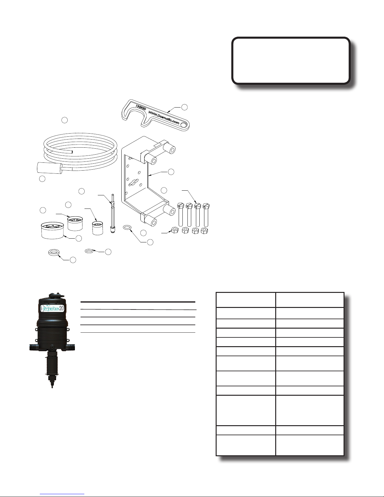
Package Contents
The injector is packaged
with the following items:
Injector (not shown) Mounting Bracket
Dosage Piston Mounting Nuts and Bolts
O-ring Filter
Manual (not shown) Suction Tube
Lower End Wrench (0.3% only)
95
195950
25
5% 011025
2.5% 010025
0.3% 010025
56
194006
27
10% 011849M
5% 011018
2.5% 011017
0.3% 003067
194309
2.5%
44
5%
51
0.3%
44
010044
44
10%
44
194022
2.5% WSP
011803
194909
58
14
212005V on the 2.5% & 5%
212007V on the 10%
57
194016
194017
17
212005VH (black)
Certied ISO 9001:2008 QMS
for the Hydro Systems Brand
Model NPT BSP
0.3% Rotating 113228R 113728R
0.3% PAA Rotating 113228RK 113728RK
2.5% 113205 113705
2.5% WSP 113205WSP 113705WSP
5% 113206 113706
10% 113207 113707
10% Remote
Injection
113232 113233
Specications
SuperDos 20 gpm
(
100 max. psi
Model 0.3% 0.025% - 0.30% (1:4000 - 1:333)
Model 2.5% 0.20% - 2.5% (1:500 - 1:40)
Model 5%** 0.4% - 5% (1:250 - 1:20)
Model 10%* 2% - 10% (1:50 - 1:10)
Flow Rate: 0.04 - 20 gpm (0,15 - 76 l/mn)
Operating Pressure: 5 - 100 psi** (0,34 - 6,9 bar)
Pipe Coupling: 1” NPT/BSP
* 10% model maximum operating pressure is
65psi (4,5 bar)
**5% with remote injection kit maximum
operating pressure is 60 psi (4bar).
)
Housing Proprietary Engineered
Dosing Accuracy +/- 10% of ratio
Repeatability +/- 3% of ratio
Pressure Loss Available upon request
Maximum Temp. 100ºF (38ºC)
Minimum Temp. 34ºF (1ºC)
Maximum vertical suction
of concentrate
Maximum horizontal
suction of concentrate
Self-Priming Yes
Seal Material Available:
*Contact your representative for
specic chemical information
Maximum Viscosity 1,500 cP (Ex. Honey)
Recommended
Accessories
Composite Material
13 Feet (3.6 Meter)
49 Feet (15 Meter)
Aas
Viton
EPDM
FFKM
Teon Coated
140 mesh (104 micron)
lter, check valve, pressure
regulator, ow restrictor.
English: 6
Safety Precautions
Warranty Compliance
Warning, Please read precautions thoroughly before operation. Must meet all applicable
!
local codes and regulations.
Remove Red Caps Prior to Installation
Your injector is 100% factory tested before delivery and
may contain a small amount of water. The three red
plastic caps are tted after testing to ensure cleanliness
of the injector.
Before Applying Aggressive Chemicals
Please consult your distributor, chemical manufacturer
or contact Hydro Systems's customer service to conrm
compatibility with your injector. Always wear proper safety
protection as recommended by chemical supplier.
Label all Fluid Lines, Valves and Connections
If the solution that is being injected is not suitable for
drinking, all uid lines should be labeled:
Warning not for human consumption!
Monitor Outlet Flow
It is the user's responsibility to monitor the output of
chemical injected.
A Filter is Recommended and Required
Install a lter of 140 mesh (104 micron) or ner
depending on your uid quality to prolong the working
life of the injector and for the warranty to be valid. A
lter is imperative since most uid contains impurities or
particles, especially if the uid source comes from a well,
pond or lake.
Avoid a Potentially Hazardous Chemical Accident
Select a safe location. Chemical container should be
kept away from children and/or high usage areas and
the location must also not be susceptible to freezing
temperatures.
Avoid Solution Contamination
Use only clean FILTERED uid. Do not allow contaminants
to enter the solution container. They can be pumped into
the uid line and may cause the spread of disease. Dirt,
debris and other contaminants in the solution container
may cause excessive wear to the unit.
Fluid Temperature
Min: 34°F (1°C) Max: 100°F (38°C)
Maximum Fluid Pressure
0.3%, 2.5%, 5% - 100 psi (6,9 bar)
10% - 65 psi ( 4,5 bar)
5% model with remote injection kit has maximum operating
pressure of 60 psi (4 bar).
Install a pressure regulator and/or pressure relief valve to
ensure operating pressure does not exceed the maximum
specication.
Before Removing An Injector From The System
Release uid pressure. While the system is in operation, turn
off the incoming uid valve. Leave the out going valve open
this will relieve the pressure at the injector and all parts of
the system after the injector. Injector is now safe to remove.
English
Please read this instruction manual thoroughly.
Following the procedures, will increase the life of your injector.
For A Long Service Life
Start with clean uid by using an inline lter to reduce
impurities. Keep the solution container covered and
clean. Keep the suction tube lter 2" (5 cm) from
the bottom of the container. Perform maintenance
procedures as recommended (see Maintenance page 10).
Liquid Concentrate, Soluble Product, Soluble and
Wettable Powder use
Ensure that the chemical, when mixing with water, is
thoroughly mixed and or completely dissolved before
using injector. For soluble and wettable powder injection,
it is recommended to use a Hydro Systems WSP injector
or install a WSPL lower end conversion kit to an existing
Hydro Systems dosage piston model injector.
General Tips
Keep From Extreme Temperature
Protect the injector from freezing temperatures or excessive heat.
Rinse Injector After Each Use
Additive allowed to remain in injector can dry out, foul
or damage the lower end at the next start-up (see
Maintenance page 10).
Injector Not in Use for an Extended Period
If the injector has not been stored properly deposits may have
dried onto the motor (see Maintenance page 10). Before
operation, soak entire unit into room temperature water
approx. 72°F (22°C) for an eight hour period.
English: 7
Operations
A
C
A
A
Clicking Sound is Normal
Fluid owing through the injector will automatically cause
the injector to “click” and inject a set amount of solution
into the uid line. The higher the ow rate the more
frequent the "clicking". The injector is designed to inject
solution proportionally (at the same set ratio) regardless
of uid ow.
Service Fluid Flow
Fluid ow and pressure must be within the established
specications (see Specication on page 6) for your
model.
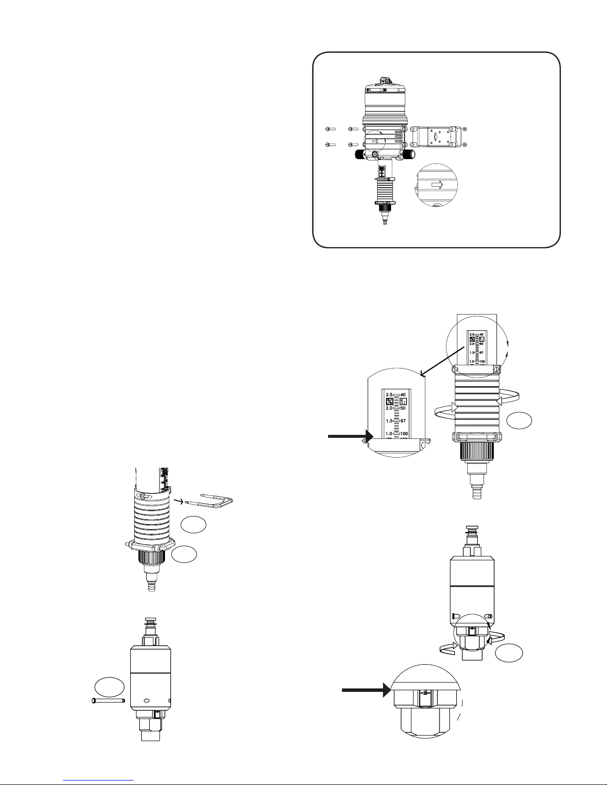
Change Feed (Injection) Rate
The feed rate on the injector is adjustable EVEN WHILE
OPERATING AND UNDER PRESSURE. To change feed
rate see (Fig. 1 and Fig. 2). Do not remove #79 when
injector is under pressure.
SuperDos 20 0.3%, 2.5% 5%
1. Remove Upper Interlock Pin (#65) (Fig. 1).
2. Rotate Ratio Adjuster Sleeve (#61) up or down to the
desired setting (Fig. 2). Use the top of the Ratio Adjuster
Sleeve to line up with the desired feed rate on the
setting (Fig. 2a).
3. Re-insert Upper Interlock Pin (#65). Clip must be
parallel with settings to be able to re-insert.
SuperDos 20 10%
1. Remove Ratio Locking Pin (#79) (Fig 1a.).
2. Rotate Outer Cylinder (#7) up or down to the desired
setting (Fig. 2b). Use the bottom of the Ratio Adjuster to
line up with the desired feed rate setting (Fig 2c)
Fig. 3
Typical wall
mounting
A
Fig. 2
A
NOTE: Do not screw Ratio Adjuster Sleeve below lowest
setting line. Measure outlet uid to assure desired feed
rate is being delivered.
Fig. 1
#65
#79
Fig. 1a
#79
Fig. 2a
Fig. 2c
#61
Fig. 2b
C
#7
English: 8

Installation and Start-up
Refer to Fig. 3 and Fig. 4
Fluid Filter (Required)
Install a lter of 140 mesh (104 micron) or ner depending
on your uid quality to prolong the working life of the injector
and for the warranty to be valid. Hydro Systems recommends a
Twist II Clean® lter that can be ordered with your injector.
Mounting Injector
Securely fasten your injector to a solid object such as a wall or in
a cold uid line. Note arrow on injector indicates uid ow.
Backow Preventor (Recommended)
Install one that meets local code requirements.
Pressure Safety Release Device (Recommended)
Prevents pressure from exceeding specications of the unit.
Bypass Valve Set-up (Recommended)
Allows the injector to be taken off-line for maintenance
or storage when not in use.
Fluid-Hammer Arrester (Recommended)
Prevents uid-hammer damage to the injector when operating
quick closing solenoid, pneumatic or hand-operated ball valves
on the uid system.
Anti-Siphon Valve (Optional)
To prevent solution from being siphoned out (from the solution
container) into the feed lines when the upstream valve is shut off.
The anti-siphon valve must be installed on the downstream outlet.
Additional Siphoning Prevention
Place solution container on a level below the injector suction tube
tting. Using the inlet side as a shut-off valve could cause full
strength solution to siphon into the feed line.
Solution Container
Use any size container. A lid or cover is recommended. To connect
your solution container, gently push the end of the suction tube
onto the bottom of the suction tube tting assembly.
Place the lter into the solution container at least 2" (5cm) from
the bottom and ll with at least 2" (5cm) of chemical solution.
Never Use Petroleum Based Lubricants
The injector is shipped with a thin coat of silicone around the
seals for ease-of-assembly. Petroleum based lubricants such as
Vaseline©, baby oil, WD40©, or motor oil on the O-rings or any part
of the injector should never be used as this can cause particles to
adhere and clog or damage the injector.
Check System for Leaks and Start-Up Procedures
Open the bypass valve (A), close inlet valve (B) and outlet
!
valve (C) to prevent uid ow into the injector. SLOWLY
turn on the main uid line. Run uid ows between 5 -12
gpm (11-45 l/m) through the plumbing system. Turn on all of the
valves located downstream from your injector to release trapped
air. SLOWLY turn on the inlet valve (B). Open the outlet valve (C)
and close valve (A). As uid travels through the injector, you will
hear a “clicking” sound. Check for leaks and correct if necessary.
English
Suggested Installation Diagram
ANTI-SIPHON
VALVE
(OPTIONAL)
FLOW CONTROL
VALVE @ OUTLET
(OPTIONAL)
PRESSURE
REGULATOR
(OPTIONAL)
BACK FLOW
PREVENTOR
(RECOMMENDED)
INLET FILTER
140 MESH / 104 MICRON
(MINIMUM REQUIRED)
PRESSURE
GAUGE
(OPTIONAL)
FILL
VALVE
(OPTIONAL)
INLET VALVE
(RECOMMENDED)
PRESSURE SAFETY
DEVICE
(RECOMMENDED)
Fig. 4
DIRECTION OF FLOW
(B)
FLOW INDICATOR
BYPASS
(A)
FLUID HAMMER
ARRESTER
(RECOMMENDED)
BYPASS VALVE
(RECOMMENDED)
OUTLET VALVE
(RECOMMENDED)
SUCTION TUBE
COVERED CONTAINER
SOLUTION FILTER
(C)
6" minimum
152.4 mm
2" REQUIRED
50 MM
English: 9

Remote Injecting
Fig. 5
Remote Injector
Kit shown on a
single injector.
0.3%, 2.5% & 5%
Models
10% Models
Maintenance
Reference numbers refer to Pages 14 - 20
RINSE INJECTOR AFTER EACH USE
Additive allowed to remain in injector can dry, foul or
damage the lower end at the next start-up. Place suction
tube into a 1 qt. (0.95 liters) or more container of fresh
ltered water. Flow fresh water through the injector by
operating until container is empty. This procedure is not
needed for continuous operation.
CLEAN SOLUTION CONTAINER
Keep covered to prevent dirt, debris from entering the
container. Rinse container thoroughly and often. Do not
mix chemicals together that might react and cause a
precipitate. Use FILTERED uid when lling container.
Remote Injector Kit (not included)
Is recommended for the following:
Kit Part Numbers
012705
Single Injector:
To prevent mineral buildup within the body of the unit.
Use when injecting chemicals that cause minerals to
precipitate from uid (see Fig. 5)
NOTE: when mixing more than one chemical, always refer
to your chemical manufacturer information guide for
proper application. Contact your local distributor or Hydro
Systems customer service for information or to order.
Perform these maintenance
procedures to extend the life of your unit.
Refer to page 15 & 16
SuperDos 20 (0.3%) Model (Including PAA)
Every 3 - 6
Months
1. Clean seal areas (#13).
2. Check #17 O-ring,
#68 Cylinder, clean
and/or replace as
necessary.
Every 6 - 12
months
1. Replace #17 O-ring
and #51 Dosage Piston
Shaft Assembly.
2. Clean and/or replace
#13 Check Poppet, #11
Suction Tube Fitting.
Replace as
necessary
1. #68 Cylinder
2. #51 Shaft
Assembly
CLEAN SUCTION TUBE FILTER SCREEN
Inspect each time new solution is added. Clean lter
screen (#27) and suction tube (#25) as necessary by
rinsing in fresh water. Replace if necessary. Keep lter
screen off bottom of solution container to prevent dirt
and precipitate from clogging lter.
CLEAN INLET FILTER
Clean or replace inlet lter as required to increase the life
of the unit as well as reduce pressure loss.
BYPASS INJECTOR
When not in use place the injector in bypass mode by
using the three valve bypass.
STORAGE
For extended storage, rinse injector (see "Rinse Injector
After Each Use") and place underwater in a container.
Apply monthly, <0.1 oz. (29 ml) of chlorine bleach to
avoid algae growth. KEEP FROM FREEZING.
Refer to page 17, 18 & 19
SuperDos 20 (2.5% & 2.5% WSP), (5%) Models
Every 3 - 6
Months
1. Clean seal areas
(#14 & #13, #44 WSP).
2. Check #17 O-ring,
#7 Cylinder, clean
and/or replace as
necessary.
Every 6 - 12
months
1. Replace #17 O-ring
and #44 Dosage Piston/
gasket (WSP model).
2. Clean & inspect #13
Check Poppet , #11
Suction Tube Fitting.
1. #7 Cylinder
2. #14 (#44 - WSP)
O-ring
Refer to page 20
SuperDos 20 (10%) Models
Every 3 - 6 Months Every 6 - 12
months
1. Clean seal areas (#14).
2. Check #17 O-ring, #7
Cylinder, clean and/or
replace as necessary.
1. Replace #17 O-ring
and #44 Dosage Piston.
Clean and/or replace.
2. Replace #60 hose kit.
Replace as
necessary
Replace as
necessary
1. #7 Cylinder
2. #14 O-ring
English: 10

Routine Maintenance Instructions
0.3%, 2.5%, 5%
↓
↓
English
Step 1.
Unscrew LOWER END
CYLINDER ASSEMBLY from
body. Remove LOWER END
CYLINDER ASSEMBLY
Step 4. For 2.5% & 5%
Replace #44 DOSAGE PISTON
ared-end up and #14 O-RING.
Step 2.
Rotate #51 SHAFT 90º and pull
from body.
↓
Step 5. For 2.5% WSP
Pinch and pull #44 DOSAGE
GASKET over the retainer lip. Slide
off the #51 SHAFT ASSEMBLY.
Step 3.
Pry the #15 SEAL RETAINER from
the injector. Pry #17 O-RING from
the unit. NOTE: O-ring may still be
seated at the base of the unit.
Step 5a. For 0.3%.
Replace LOWER SHAFT ASSEMBLY
#51 into upper shaft.
Step 6.
Reinsert #15 SEAL RETAINER
and #17 O-RING onto # 51
SHAFT ASSEMBLY.
Step 7.
Reinsert #51 SHAFT ASSEMBLY into
body and rotate 90º to lock. Conrm
the shaft is locked in by gently
tugging on the shaft. Shaft should
remain inserted.
Step 8.
Screw LOWER END CYLINDER
ASSEMBLY onto body. Ensure
#16 GASKET is seated on the top
of cylinder assembly.
English: 11

Routine Maintenance Instructions - 10%
↓
Step 1.
Unscrew LOWER END
ASSEMBLY from body.
Step 4.
Remove the #73 DOSAGE PISTON
GUIDE and replace #44 DOSAGE
PISTON and #14 O-ring.
Step 2.
Remove LOWER END ASSEMBLY .
↓
Step 5. Unscrew #72 ADAPTER and
remove.
Step 3.
Remove #93 CAPSCREW from the
end of the shaft using a wrench
and nut driver.
Step 6.
Remove and replace #17 O-RING
Step 7.
Re-install the new #44 DOSAGE
PISTON and #73 DOSAGE PISTON
GUIDE. Tighten snug using a nut
driver.
English: 12
↓
Step 7a.
NOTE: #44 DOSAGE PISTON must
be installed ared end up.
↓
↓
Step 8.
Screw LOWER END ASSEMBLY
onto body. Hand tighten only.

Troubleshooting
New Install - Always Pressure Up Slowly (Follow start up on page 9)
Problem Cause Solution
Are the red plugs at the inlet, outlet and suction tube tting openings removed?
Is the unit installed backward? The arrow on the unit must point in the
Fluid not owing through system
No Clicking
Sound
Fluid owing through system
Injector in Operation or After Scheduled Maintenance
Problem Cause Solution
Main Piston Assembly #9 worn Replace # 9 Main Piston Assembly. Clean uid lter.
Cover #1 or main body #40 worn
No Clicking
Sound
or scored
By-Pass Valve (A) not closed Set By-pass valve (A) to the closed position.
Dirty or plugged inlet lter Ensure mesh size is correct for proper ltration. Clean lter.
#17 Worn or not seated properly Re-seat #17 or replace.
direction of the uid ow.
If still not clicking, do not open the upper body. Call Hydro Systems
Customer Service.
Fluid rate is below or exceeds rated service ow of injector. (see
Specications page 6).
Has the new injector been stored for an extended period. If so, submerge
the injector in room temperature uid for 24 hours so that the working
parts can reabsorb uid and swell back to the proper size.
If below increase ow rate, if above, reduce ow rate.
Operating pressure exceeds maximum limit. Install a pressure reducer
valve. (see Specications page 6).
By-Pass Valve (A pg.9) not closed. Check and set valve to the OFF
position.
Replace and install or clean uid lter.
English
Problem
Clicking
Sound
No Suction Of
Solution
Cause
Cylinders #7 or #68 worn. Replace.
Dosage piston/gasket (WSP model)
#44 (0.3% model #51) worn or
installed incorrectly
O-ring retainer #15 installed
incorrectly
O-ring seat #14 or dosage piston/
gasket #44 (0.3% model #51)
damaged
#17 O-ring worn and/or loose Replace.
Suction tube #25 or suction tube
tting #11 cracked, leaking or
clogged suction tube lter
Check valve #13 leaking Clean & replace as necessary.
Replace. Ensure during maintenance replacement that #44 was
installed correctly ared-end up.
Install correctly.
Replace.
Replace and/or clean as necessary.
Solution
Problem Cause Solution
Clicking
Sound.
Under
Injecting
#44 (0.3% model #51) Dosage
Piston/gasket (WSP model) worn
#7 (#68 - 0.3%) Inner Cylinder worn Replace.
Unit operates at high-ow and not
at low ow
Main Piston Assembly #9 worn Replace # 9 Main Piston Assembly. Clean uid lter.
Cover #1 or main body #40 worn
or scored
Replace.
Replace #17 O-ring.
Replace and install or clean uid lter.
Problem
Fluid
Re-lling
Solution Tank
Check valve #13 leaking Check seat area on suction tube tting #11. Check valve and seal must
Washer seal on #13 is swollen or
chemical attack
Cause
Solution
t loose in the suction tube tting. Clean seal and inside tting for debris.
Replace with new check valve assembly.
English: 13

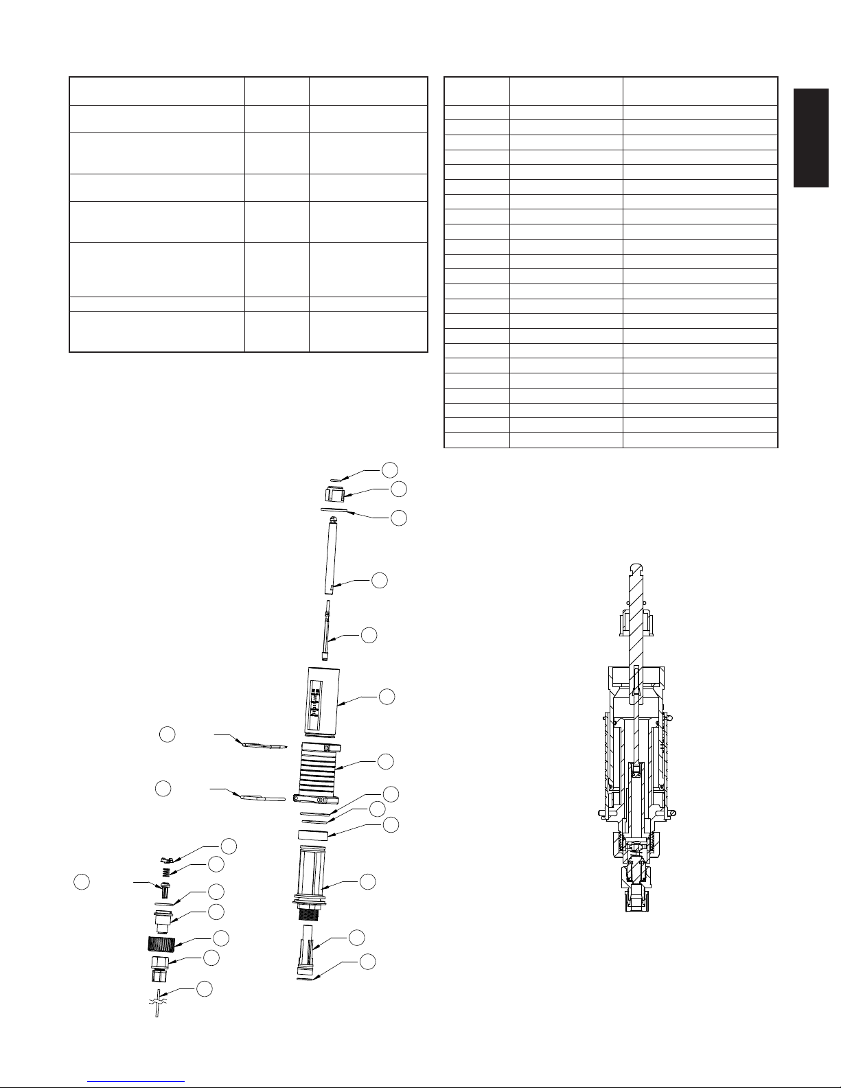
Injector Repair Parts
Ref. # Part # Description
1 194610 Upper Body (Must Order W/#88)
3 194605 Mixing Chamber Gasket
9 011876VH Piston Assembly (Must Order With #21)
9 011879T Piston Assembly 10% (Must Order With #21)
21 011172 Shaft Assembly
34 004014 Hairpin
40 011031 Lower Body NPT 1"
40 011031B Lower Body BSP 1"
85 194612 Upper Shaft Pin
88 194615 Non Bypass Plug
89 197090 Washer
85
194612
1
194610
89
197090
88
21
194615(2x)
34
004014
011172
9
011876
011879T 10%
3
194605
English: 14
40
011031 NPT
011031B BSP
Lower end & wear parts kits 0.3% PAA(Rotating):
Kit A – Wear Parts Kit (shaft assy,
O-ring)
Kit C – Wear Parts Kit (Kit A, inner
cylinder, O-ring)
Kit D – Suction Tube Fitting Assy
(O-ring, spring, tting, twistlock,
check poppet)
Kit E – Wear Parts Kit (Kits C & D,
gasket)
Kit F – Lower End Cylinder Kit (inner
& outer cylinder, ratio adjuster,
O-rings, pins, gasket, lower end stop)
Kit G - Complete Lower End, solution
tube, compression tting
Kit H – Motor Piston Assy 011863 9, 21
Kit M – Mounting Bracket Kit
(mounting bracket, 4 hex caps &
nuts)
012310K 17, 51
012311RK 17, 51, 63, 68
011463RK 10, 11, 12, 13, 80
012312RK 10, 11, 12, 13, 16, 17,
51, 63, 68, 80
012313RK 7, 16, 61, 63, 64, 65,
66, 67, 68, 78,79
012314RK 7, 10, 11, 12, 13, 15,
16, 17, 25, 27, 51, 52,
61, 63, 64, 65, 66, 67,
68, 71, 78, 79, 80
011432 56, 57, 58
Manual
Reference
7 194408 Cylinder, inner
10 194418H Spring
11 011452 Suction tube tting
12 212120X O-ring
13 011453F Check poppet
15 194004 Seal retainer, O-ring
16 010016S Lower End Gasket
17 212005K O-ring
25 010029 Suction tube, 1/4” ID x 5ft
27 005230 Compression tting
51 011803K Lower shaft Assy.
52 194007 Upper shaft
61 194406P Ratio adjustment sleeve
63 212516X O-ring
64 212017X O-ring, inner cylinder, lower end
65 194310D Pin, upper interlock
66 212025V O-ring, outer cylinder, lower end
67 194611 Cylinder, outer
68 194030 Cylinder, inner for #7
71 194414 Nut, suction tube tting
78 194620 Lower end stop
79 194410SS Pin, narrow interlock
80 194415 Twistlock
Part # Description of Part
English
13
011453F
65
79
194310
194410
10
12
11
80
194415
194418
212120X
011452
52
51
64
7
17
212005K
15
16
194007
011803K
67
194611
61
194406
66
212025V
212017X
78
194620
194408
194004
010016
71
194414
27
005230
25
010029
68
194030
63
212516X
Lower End
Assembly
English: 15

Lower end & wear parts kits 0.3% (Rotating):
Kit A – Wear Parts Kit (shaft assy, O-ring) 012310 17, 51
Kit C – Wear Parts Kit (Kit A, inner cylinder,
012311R 17, 51, 63, 68
O-ring)
Kit D – Suction Tube Fitting Assy (check
poppet, O-ring, spring, tting, twistlock)
011463V 10, 11, 12, 13,
80
Kit E – Wear Parts Kit (Kits C & D, gasket) 012312R 10, 11, 12, 13,
16, 17, 51, 63,
68, 80
Kit F – Lower End Cylinder Kit (inner & outer
cylinder, ratio adjuster, O-rings, pins, gasket,
lower end stop)
Kit G - Complete Lower End, lter, solution
tube
012313R 7, 16, 61, 63,
64, 65, 66, 67,
68, 78,79
012314R 7, 10, 11, 12,
13, 15, 16, 17,
25, 27, 51, 52,
61, 63, 64, 65,
66, 67, 68, 71,
78, 79, 80
Kit H – Motor Piston Assy 011863 9, 21
Kit M – Mounting Bracket Kit (mounting
011432 56, 57, 58
bracket, 4 hex caps & nuts)
17
212005
15
194004
16
010016
25
010025
52
194007
Manual
Part # Description of Part
Reference
7 194408 Cylinder, inner
10 194418H Spring
11 194417 Fitting, suction tube, ¼”
12 212120
O-ring
*Must specify material
13 011453A Check poppet
15 194004 Seal retainer, O-ring
16 010016 Lower End Gasket
17 212005
O-ring
*Must specify material
25 010025 Suction tube, ¼” x 5’
27 003067 foot valve ¼” ID
51 011803
Lower shaft assy.
*Must specify material
52 194007 Upper shaft
61 194406P Ratio adjustment sleeve
63 212516
*Must specify material
64 212017
*Must specify material
O-ring, inner cylinder
(#68)
O-ring, inner cylinder,
lower end
65 194310D Pin, upper interlock
66 212025
*Must specify material
O-ring, outer cylinder,
lower end
67 194611 Cylinder, outer
68 194030 Cylinder, inner for #7
71 194414 Nut, suction tube tting
78 194620 Lower end stop
79 194410SS Pin, narrow interlock
80 194415 Twistlock
13
011453A
65
79
194310
194410
27
10
11
003067
80
194418
12
194417
68
71
63
194415
212120
194030
194414
212516
78
51
67
61
64
7
011803
194611
194406
66
212017
194620
194408
212025
Lower End
Assembly
English: 16

Lower end injector & wear parts kits 2.5%:
Kit A – Wear Parts Kit (dosage
piston and O-rings)
Kit B – Wear Parts Kit (Kit A &
shaft)
Kit C – Wear Parts Kit (Kit A,
inner cylinder and O-ring)
Kit D – Suction Tube Fitting Assy
(check poppet, O-ring, spring,
tting, twistlock)
Kit E – Wear Parts Kit (Kits C &
D, shaft, gasket)
Kit F – Lower End Cylinder Kit
(inner & outer cylinder, ratio
adjuster, O-rings, pins, gasket)
Kit G - Complete Lower End,
lter, solution tube
Kit H – Motor Piston Assy 011863 9, 21
Kit M – Mounting Bracket Kit
(mounting bracket, 4 hex caps
& nuts)
011850V 14, 17, 44
011945V 14, 17, 44, 51
011850CV 7, 14, 17, 44, 64
011463V 10, 11, 12, 13, 80
011833PV 7, 10, 11, 12, 13,
14, 16, 17, 44, 51,
64, 80
011961V 7, 16, 61, 64, 65, 66,
67, 79
011843PV 7, 10, 11, 12, 13, 14,
15, 16, 17, 25, 27,
44, 51, 61, 64, 65,
66, 67, 71, 79, 80
011432 56, 57, 58
17
16
212005
15
44
194004
010016
010044
Manual
Reference
7 194404P Cylinder, inner
10 194418 H Spring
11 194 417 Fitting, suction tube,
12 212120
13 011453A Check poppet
14 212005
15 194004 Seal retainer, O-ring
16 010016 Lower End Gasket
17 212005
25 010025 Suction tube, 1/4” x 5’
27 011017 Filter, for suction tube,
44 010044P Dosage Piston
51 194301F Shaft
61 194406P Ratio adjustment sleeve
64 212017
65 194310D Pin, upper interlock
66 212025
67 194407P Cylinder, outer
71 194414 Nut, suction tube tting
79 194410SS Pin, narrow interlock
80 194415 Twistlock
Part # Description of Part
1/4”
*Must specify material
*Must specify material
*Must specify material
*Must specify material
*Must specify material
O-ring
O-ring
O-ring
1/4” ID
O-ring, inner cylinder,
lower end
O-ring, outer cylinder,
lower end
English
11
13
194417
011453A
194413
194416
65
79
194310
194410
010025
011017
80
10
194418
12
25
27
194415
212120
14
51
67
66
64
212005
194301
194407P
212025
61
194406
212017
7
194404
71
194414
Lower End
Assembly
English: 17

Lower end injector & wear parts kits 2.5% WSP:
Kit A – Wear Parts Kit (dosage
011850WSP 17, 44
gasket and O-rings)
Kit B – Wear Parts Kit (Kit A,
011945WSP 17, 44, 51
& shaft)
Kit C – Wear Parts Kit (Kit A,
011850CWSP 7, 17, 44, 64
inner cylinder and O-ring)
Kit D – Suction Tube Fitting
011463V 10, 11, 12,13, 80
Assy (check poppet, O-ring,
spring, tting, twistlock)
Kit E – Wear Parts Kit (Kits C &
D, shaft, gasket)
011833WSP 7, 10, 11, 12, 13,
16, 17, 44, 51,
64, 80
Kit F – Lower End Cylinder Kit
(inner & outer cylinder, ratio
011961WSP 7, 16, 61, 64, 65,
66, 67, 79
adjuster, O-rings, pins, gasket)
Kit G - Complete Lower End,
lter, solution tube
011843WSP 7, 10, 11, 12, 13,
15, 16, 17, 25, 27,
44, 51, 61, 64, 65,
66, 67, 71, 79, 80
Kit H – Motor Piston Assy 011863 9, 21
Kit M – Mounting Bracket Kit
011432 56, 57, 58
(mounting bracket, 4 hex caps
& nuts)
17
16
212005
15
010016
194004
Manual
Part # Description of Part
Reference
7 194023 Cylinder, inner
10 194418 H Spring
11 194 417 Fitting, suction tube,
1/4”
12 212120
O-ring
*Must specify material
13 011453A Check poppet
15 194004 Seal retainer, O-ring
16 010016 Lower End Gasket
17 212005
O-ring
*Must specify material
25 010025 Suction tube, 1/4” x 5’
27 011017 Filter, for suction tube,
1/4” ID
44 194022 Dosage Gasket
51 194019 Shaft
61 194406P Ratio adjustment sleeve
64 212027
*Must specify material
O-ring, inner cylinder,
lower end
65 194310D Pin, upper interlock
66 212025
*Must specify material
O-ring, outer cylinder,
lower end
67 194407WSP Cylinder, outer
71 194414 Nut, suction tube tting
79 194410SS Pin, narrow interlock
80 194415 Twistlock
13
011453A
194413
194416
79
65
194310
194410
25
10
11
71
27
80
12
010025
011017
194415
194418
212120
194417
194414
44
64
7
51
194022
67
66
61
194023
194019
194407WSP
194407P
212025
194406
212027
Lower End
Assembly
English: 18

Lower end injector & wear parts kits 5%:
Kit A – Wear Parts Kit (dosage
011852PV 14, 17, 44
piston and O-rings)
Kit B – Wear Parts Kit (Kit A, &
011950V 14, 17, 44, 51
shaft)
Kit C – Wear Parts Kit (Kit A, inner
cylinder and O-ring)
Kit D – Suction Tube Fitting Assy
(check poppet, O-ring, spring, tting,
011856PV 7, 14, 17, 44,
64
011462V 10, 11, 12, 13,
77, 80
twistlock, barb)
Kit E – Wear Parts Kit (Kits C & D,
shaft, gasket)
011836PV 7, 10, 11, 12,
13, 14, 16, 17,
44, 51, 64,
77, 80
Kit F – Lower End Cylinder Kit (inner
& outer cylinder, ratio adjuster,
011963PV 7, 16, 61, 64,
65, 66, 67, 79
O-rings, pins, gasket)
Kit G - Complete Lower End, lter,
solution tube
011846PV 7, 10, 11, 12,
13, 14, 15, 16,
17, 25, 27, 44,
51, 61, 64, 65,
66, 67, 71, 77,
79, 80
Kit H – Motor Piston Assy 011863 9, 21
Kit M – Mounting Bracket Kit
011432 56, 57, 58
(mounting bracket, 4 hex caps &
nuts)
212005
194004
010016
194309
212005
Manual
Reference
Part # Description of Part
English
7 194405P Cylinder, inner
10 194 418H Spring
11 011452 Suction Tube Ftting
12 212120
O-ring
*Must specify material
13 011453A Check Poppet
14 212005
O-ring
*Must specify material
15 194004 Seal retainer, O-ring
16 010016 Lower End Gasket
17 212005
O-ring
*Must specify material
25 011025 Suction tube, 1/2” x 5’
27 011018 Filter, for suction tube, 1/2” ID
44 194309 Dosage Piston
51 194301F Shaft
61 194406P Ratio adjustment sleeve
64 212017
O-ring, inner cylinder, lower end
*Must specify material
65 194310D Pin, upper interlock
66 212025
O-ring, outer cylinder, lower end
*Must specify material
67 011918P Cylinder, outer
17
15
16
44
14
71 194414 Nut, suction tube tting
77 003039 Hose Barb 1/2” x 3/8”
79 194410SS Pin, narrow interlock
80 19 4415 Twistlock
13
011453A
194413
194416
65
79
194310
194410
194415
194418
212120
011452
194414
003039
194301
51
011918P
67
66
212025
194406
61
80
10
12
11
71
77
212017
194405
64
7
25
011025
27
011018
Lower End
Assembly
English: 19

Lower end injector & wear parts kits 10%:
Kit A - Wear Parts Kit (Dosage Piston,
011138 14, 17, 44
O-rings)
Kit B – Wear Parts Kit (Hose kit) 011849M 60
Kit C - Wear Parts Kit (Kit A, O-ring) 011107 7, 14, 17, 44, 91
Kit H – Motor Piston Assy 011879T 9, 21
Kit M – Mounting Bracket Kit
011432 56, 57, 58
(mounting bracket, 4 hex caps &
nuts)
51
011908
194343
(#51 is part of the
011879T piston assy)
17
212005
15
194004
68
212002
72
194830
194342
212010
194832
53
194344
Manual
Part # Description of Part
Reference
7 011921P Outer Cylinder
14 212007
O-ring, Dosage Piston Guide
*Must specify material
15 194004 Seal Retainer, O-ring
17 212005
O-ring
*Must specify material
44 194909 Dosage Piston
51 011908 Shaft Assembly, Stainless Steel
53 194344 Klipring
61 194831 Ratio Adjuster
66 212402
O-ring, Outer Cylinder, Lower End
*Must specify material
68 212002
O-ring, Cylinder Adapter, Lower End
*Must specify material
72 194830 - Standard
Adapter
190830 - Remote Injection
73 194833 Dosage Piston Guide
79 195911 Ratio Locking Pin
93 193003 Capscrew 10-32 X 1/2” Ss Hex
92 195861 Shaft Cap
94 212012
O-ring, Outer Cylinder
*Must specify material
91 212518
O-ring, Dosage Piston Guide
*Must specify material
60 011849M
Hose Kit
*Must specify material
60
011849M (Kit)
79
195911
61
66
194831
94
7
011921P
212402
44
14
73
91
92
93
212012
194909
212007
194833
212518
195861
193003
Remote Injection Kit
(Factory Installed)
Remote Injection Port
7
53
68
72
190830
44
14
73
91
92
93
94
212012
011921P
194344
17
15
212002
194909
212007
194833
212518
195861
193003
212005
194004
51
011908
194343
194342
212010
194832
(# 51 is part of the
011879T piston assy)
English: 20
60
011849M (Kit)
79
195911
61
66
194831
212402
Lower End
Assembly

Warranty
English
Congratulations on Your Purchase
We make the best and most reliable uid-driven injectors
available. Our warranty provides the best coverage in the
industry. Hydro Systems will provide for replacement of all
parts proven to be defective in material or workmanship
from the date of purchase for the following periods:
3 years The cover and body
2 years The motor piston assembly
1 year The lower end (Chemical pump)
Hydro Systems products are warranted to be free from
defects in materials and workmanship for the above time
frames. Hydro Systems will at its sole option repair or
replace any component that fails in normal use. Any repairs
made under warranty shall not extend the initial warranty
period.
To Maintain Your Warranty
Your only responsibility is ordinary maintenance - ltering
incoming uid, replacing the O-ring and dosage piston when
worn. Seals and O-rings are not covered under the warranty.
This warranty is not valid if the defects are found to be
due to the product’s misuse, lack of maintenance, uid
continued...
impurities such as sand or iron, defective installation, freezing,
uid hammer, abuse, unwanted side effects due to the
chemicals you choose to inject or service provided by anyone
who is not an authorized service provider. Hydro Systems
declines any responsibility if the product is not used in
compliance with the operating instructions and specications
as indicated in this owner’s manual.
Warranty may be void if injector body is disassembled. If
you suspect you are having a problem in the motor piston
assembly or inside the body please contact Hydro Systems or
any authorized repair center to arrange to send the injector in
to be evaluated and/or repaired.
IN NO EVENT SHALL Hydro Systems BE LIABLE FOR ANY
INCIDENTAL, SPECIAL; INDIRECT, OR CONSEQUENTIAL DAMAGES,
WHETHER RESULTING FROM THE USE, MISUSE OR INABILITY TO
USE THIS PRODUCT OR FROM DEFECTS IN THE PRODUCT.
There is no warranty expressed or implied relating in any way
to products used in conjunction with Hydro Systems.
Hydro Systems or authorized distributor shall not be liable for
incidental or consequential damage, such as any economic loss.
Hydro Systems retains the exclusive right to repair or replace the
product. Such remedy shall be your sole and exclusive remedy
for any breach of warranty. There are no warranties, expressed
or implied, which extend beyond those described above.
To Return an injector for Warranty or Non-Warranty repair:
See page 3 for Hydro Systems contact information.
1. Thoroughly ush the injector with water of any chemical and drain. Ensure proper packing for shipment.
2. To EXPEDITE warranty evaluation and repair or non-warranty product repair, please include the following:
a copy of the original invoice, serial number of the unit, chemical used, contact information and a Return
Authorization (RA) number, contact your country's Hydro Systems Customer Service to obtain.
3. Send freight prepaid and ship to Hydro Systems or your local distributor. For the name of your local distributor or if
returning to Hydro Systems, contact your country's Hydro Systems Customer Service.
4. For a WARRANTED injector: upon inspection and determination that the unit has defects in materials or
workmanship, the unit will be repaired or replaced at Hydro Systems’s option, free of charge and shipped back
freight prepaid.
5. For a NON-WARRANTED injector: upon inspection Hydro Systems or a local distributor will call the customer
with a repair estimate.
English: 21
 Loading...