

Hydro systems Designer Safety Instructions

MR. INSTALLER -
Please pass these
IMPORTANT
instructions along
to the homeowner!
IMPORTANT SAFETY INSTRUCTIONS
GENERAL INSTRUCTIONS
INSTRUCTIONS PERTAINING TO A RISK OF FIRE, ELECTRIC SHOCK, OR INJURY TO PERSONS.
TABLE OF CONTENTS
Follow All Instructions, Installation Instructions, General Requirements ...............................PAGE 2
General Requirements For Installation cont. .........................................................................PAGE 3
Electrical Requirements, Installing The Tub ..........................................................................PAGE 4
Test The Whirlpool System, Setting The Tub ........................................................................PAGE 5
Operating Instructions, Figure 3 ............................................................................................PAGE 6
User Care And Maintenance .................................................................................................PAGE 7
Limited Warranty ...................................................................................................................PAGE 8
– 1 –

WARNING: When using your Hydro Systems whirlpool tub, basic precautions should be followed.
READ AND FOLLOW ALL INSTRUCTIONS.
1. DANGER: To reduce the risk of injury, do not permit children to use this unit unless they are closely supervised
at all times.
2. Use this unit only for its intended use as described in this manual. Do not use attachments not recommended
by the manufacturer.
3. Never drop or insert any object into any opening.
4. Do not operate this unit without suction cover installed.
5. The unit must be connected only to a dedicated electrical supply circuit that is protected by a Ground Fault
Circuit Interrupter (GFCI). The GFCI must be provided by the installer and should be tested on a routine basis by
the homeowner. To test the GFCI push the test button. The GFCI should interrupt power. Push the RESET button.
Power should be restored. If the GFCI fails to operate in this manner there is a ground current fault, indicating
the possibility of an electric shock. Do not use the tub. Disconnect the power and have the problem corrected by
a qualied service representative. Re-test the GFCI and only when it is operating properly may the whirlpool tub
be used.
6. A terminal is provided on the exterior of most equipment. To reduce the risk of electric shock, connect this terminal
to the grounding terminal of your electric service or supply panel with a conductor equivalent in size to the circuit
conductors supplying this equipment.
Save These Instructions
INSTALLATION INSTRUCTIONS
Hydro Systems bathtubs and whirlpool bathtubs are designed and engineered for easy installation and years of
trouble-free enjoyment. Installation is easy if you follow the step-by-step instructions. Please read all instructions
before you begin the installation.
WARNING: - When using electrical products, basic precautions, should always be followed.
1. DANGER: RISK OF ELECTRICAL SHOCK. Connect only to a circuit protected by a ground fault circuit interrupter.
2. This unit should be installed by a qualied service representative. All electrical connections should be made by a
licensed electrician. Grounding is required.
3. The installaion of Hydro Systems bathtubs must meet all applicable codes and regulations.
ELECTRICAL REQUIREMENTS:
A dedicated 20AMP GFCI Protected outlet(s) for pump, 15 amp blower, 15 amp heater.
WARNING: When using electrical products, basic percautions should always be followed.
DANGER: RISK OF ELECTRICAL SHOCK. Connect only to a circuit protected by a ground fault circuit interrupter.
Grounding is requirred. All electrical connections should be made by a licensed electrician. Installation of
Hydro Systems bathtubs must meet all a[pplicable codes and regulations.
Note: Access panel must be provided for servicing.
– 2 –
GENERAL REQUIREMENTS FOR INSTALLATION
MECHANICAL REQUIREMENTS:
1. WEIGHT: Tubs must be installed in a location that will support the combined weight of the tub plus the water
plus the bather. As a rule of thumb, this will be a maximum of 1000 lbs. for a 60" tub, 1200 lbs. for a 66" tub, and
1400 lbs. for a 72" tub.
2. TILE FLANGES: Tubs can be installed as a drop-in unit or they can be installed against one, two or three walls.
Tubs installed against walls should be ordered with a tile ange on each side that will be against a wall to
provide a leak free water barrier.
3. FRAMING: When framing it is best to measure the actual tub to be installed to determine faming dimensions.
In the abscence of the actual tub, refer to the Hydro Systems catalog drawings or website at www.hydrosystem.com.
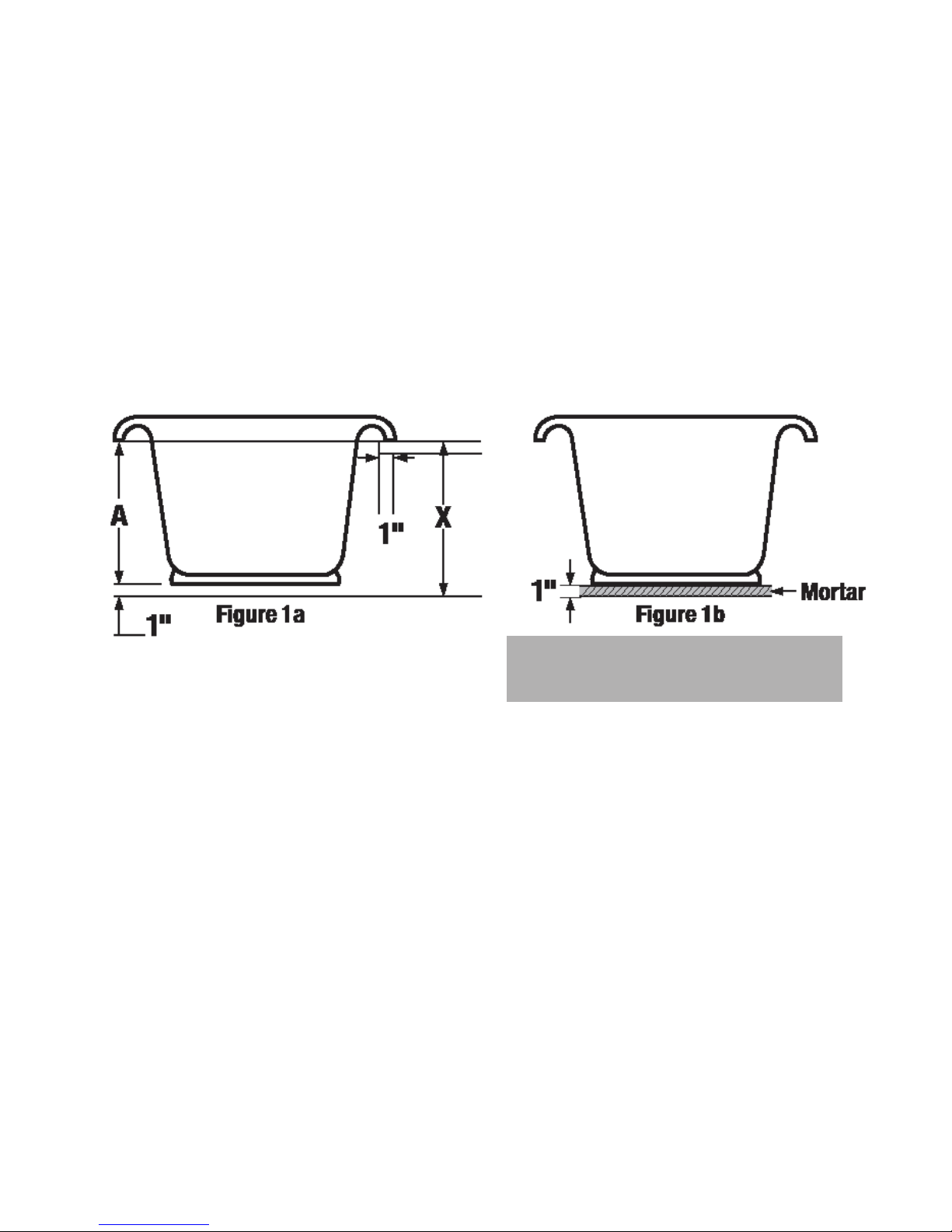
The two most common types of installations are DROP-IN and THREE WALL installations. DROP-IN (Figure 1)
For drop-in, or deck-mounted tubs, the nished height of the deck (X) where the tub will sit must equal the
dimension from the trimmed edge of the tub to the oor at the drain end of the tub (A) plus 1”. The 1” is for
the mortar bed.
NOTE: Tub lip resting on ledge, stringer or frame
is non-weight bearing.
Tub MUST be supported by mortor only.
IMPORTANT - the deck must be level both front to back and side to side. If it is not level, the tub will not be level
and it will not drain properly. The opening into which the tub will be dropped should be cut 1" smaller than the tub all
around. For example, for a 60" x 42" rectangular tub, an opening 58" x 40" will extend 1" under the lip of the tub all the
way around and will provide clearance for the whirlpool system. In the case of oval and round tubs, Hydro Systems ships
a full size paper template with the tub.
THREE WALL: For tubs installed in a three wall enclosure, the tub will need a rough opening the same size as its
overall dimensions. For example, a 60" x 42" tub will need a space 60" x 42" for installation. Do not include nish
wall coverings (wall board, tile, etc) in your rough framing calculations. Studs and walls should be straight and plumb,
and corners must be square. Stringers must be provided to support the deck where it meets the wall.
IMPORTANT - The stringers must be level both front to back and side to side. If they are not level, the tub will
not be level and it will not drain properly.
On tubs with integral tile anges, (Figure 2a) measure the distance from the underside of the tub deck to the bottom
of the tub base at the drain end of the tub (A) plus 1" for the mortar bed. On tubs with integral tile anges and a skirt
panel, (Figure 2b) measure the distance from the top of the stringer to the oor (X) must equal the distance from the
bottom of the skirt to the top of the deck (B), minus 1/4" (the thickness of the tub deck).
– 3 –
 Loading...