

Page 1

user manual
CP-5OO
warewash dispenser
Page 2

(This page was intentionally left blank.)
Page 3

index
1.OO overview page
1.01 Package Contents 4
1.02 Operation 4
1.03 General Specifications 4
1.04 Model Numbers and Features 5
2.OO installation
2.01 Site Survey & Installation Requirements 6
2.02 Wall Mount 6
2.03 Mechanical Installation 7
2.04 Electrical Installation and Programming 8
3.OO operation
3.01 Description of Controls 13
4.OO service parts 13
5.OO maintenance
5.01 Maintenance (Required) 14
5.02 Pump Tube Replacement 14
6.OO troubleshooting
6.01 Troubleshooting Table 15
7.OO specifications
7.01 Specifications 15
8.OO warranty
8.01 Limited Warranty 16
8.02 Limitation of Liability 16
Page 4
1.OO overview
Safety Precautions
WARNING! Please read precautions thoroughly before operation. Meet all applicable local codes and regulations.
THANK YOU FOR YOUR INTEREST IN OUR PRODUCTS
Please use this equipment carefully and observe all warnings and cautions.
protective clothing and eyewear when dispensing chemicals or other materials or when working in the
WEAR
vicinity of all chemicals, filling or emptying equipment, or changing metering tips.
observe safety and handling instructions of the chemical manufacturer.
direct discharge away from you or other persons or into approved containers.
dispense cleaners and chemicals in accordance with manufacturer’s instructions. Exercise CAUTION when
ALWAYS
maintaining your equipment.
reassemble equipment according to instruction procedures. Be sure all components are firmly screwed or
latched into position.
equipment clean to maintain proper operation.
KEEP
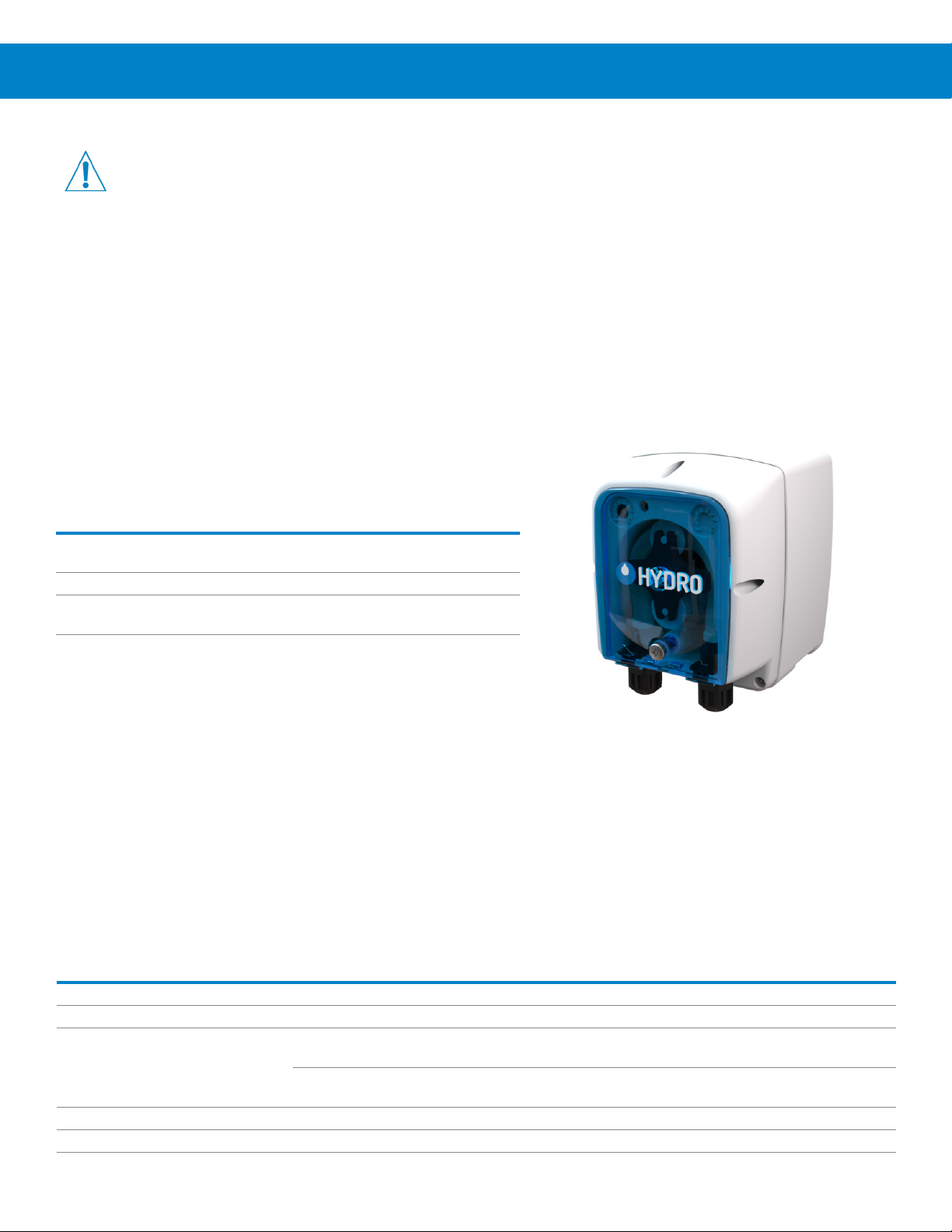
1.O1 Package Contents
CP-500 Warewash Dispenser (part number varies by model)
• CP-500 Dispenser
(Part number varies by model)
• Quick Start Guide (P/N HYD10099215)
• Accessory Kit: Mounting bracket, fittings, hardware, and pickup tubing
(Part number varies by model)
• Pump Squeeze Tube (not installed)
Detergent models use Santoprene® tubes as standard
Rinse models use silicone tubes as standard
(Part number varies by model)
1.O2 Operation
The CP-500 is a globally versatile, single product dispenser used to supply detergents or rinse aid into automatic dish
machines. Designed with simplicity in mind, the unit can be installed in minutes and requires no programming; all settings
can be configured using potentiometers that control the time or speed of dosing (depending on the model). The unit has the
reliability and accuracy you expect from Hydro Systems Co. at an economic price point.
NOTE! The CP-500 is intended for use in industrial applications. It is not suitable for domestic use, and it must not be used
outside of its intended use. The product must only be used for commercial dish washing operations. The manufacturer waives
any responsibility arising from incorrect usage or transportation.
1.O3 General Specifications
Category Specification
Electrical 90 to 260 VAC at 50/60Hz
Chemical Temperature Rating Intake chemicals should be at room temperature
Regulatory Approvals (CE) 89/336/CEE
73/23/CEE
Cabinet Material Front: Polypropylene - Rear: Polypropylene
Environmental Pollution: Degree 2, Temperature: 50°to 104° F (10° to 40° C), Maximum Humidity: 95% Relative
Dimensions 5.0 in (128 mm) High x 3.6 in (91 mm) Wide x 4.1 in (104 mm) Depth
4
(Regarding “Electromagnetic Compatibility” and the subsequent modifications
to 92/31/CEE, 93/68/CEE, 93/97/CEE)
(Regarding “Low Voltages”, and the subsequent modifications to 93/68/CEE,
2002/95/CE, 2002/96/CE, 2003/108/CE “RoHs and WEEE Directive”)
Page 5
1.OO overview (continued)
1.O4 Model Numbers and Features
Pump Build Options:
Pump Type: D = Detergent
R = Rinse
Adjustment: 1T = Time
Combo 1TT = Time Time
Pressure: 1 = 1 bar (14.5 psi)
3 = 3 bar (43.5 psi)
Tube Material: SA = Santoprene
SI = Silicon
2TT = 2 Solenoids Time Time
1S = Speed
1SS = Speed Speed
Level Input: N = None
L = Level Included
1ST = Rinse by Time and Speed
Electrical CE = CE
Flow Rate: 017 = 17 ml per minute
067 = 67 ml per minute
Approvals: UL = UL
100 = 100 ml per minute
Build Example: HYDCP500- R 1S 017 3 SI N UL
Model Builder:
Popular UL Models (1 Valve Dish Machine)
HYDCP500-D1TT1001SANUL HYD CP500- D 1TT 100 1 SA N UL
HYDCP500-R1ST0171SINUL HYD CP500- R 1ST 017 1 SI N UL
Popular UL Models (2 Valve Dish Machine)
HYDCP500-D2TT1001SANUL HYD CP500- D 2TT 100 1 SA N UL
HYDCP500-R1S0173SINUL HYD CP500- R 1S 017 3 SI N UL
Popular CE Models (1 Valve Dish Machine)
HYDCP500-D1TT1001SANCE HYD CP500- D 1TT 100 1 SA N CE
HYDCP500-R1ST0171SINCE HYD CP500- R 1ST 017 1 SI N CE
Popular CE Models (2 Valve Dish Machine)
HYDCP500-D2TT1001SANCE HYD CP500- D 2TT 100 1 SA N CE
HYDCP500-R1S0173SINCE HYD CP500- R 1S 017 3 SI N CE
Hydro
Prefix
Base
Model
Pump
Type
Adjustment
Combo
Flow
Rate
Pressure
Tube
Material
Level
Input
Electrical
Approvals
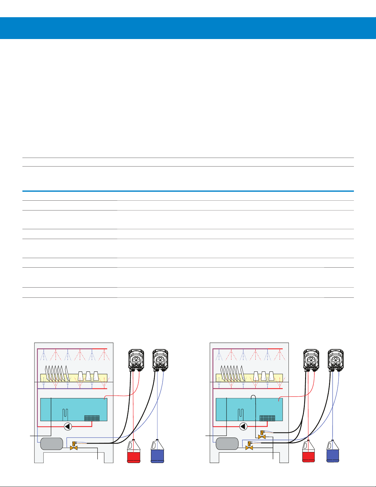
Wiring Example - Single-Valve Dish Machine
D
1TT
R
1ST
Wiring Example - Two-Valve Dish Machine
D
2TT
R
1S
5
Page 6

2.OO installation
2.O1 Site Survey & Installation Requirements
WARNING! This product is intended to be installed by experienced installers, in accordance with all applicable
electrical and plumbing codes.
• Unit must not be installed near areas that suffer excess temperature changes, direct sunlight, frost or moisture
of any kind.
• Area must be free of high levels of electrical noise.
• Ensure the unit can be mounted in an accessible position above the height of the required discharge location.
• Unit must be mounted on a suitable wall, that is flat and perpendicular to the floor.
• The unit location should be well lit for any maintenance and free of high levels of dust / air particulates.
• Scheduled maintenance should be carried out on the dispenser at least once per year.
2.O2 Wall Mount
Back of Unit
72mm
(2.8 in)
High
60.5mm
(2.4 in)
Wide
Mounting Bracket
Mounting Bracket
1) Choose an installation location that is:
• Within 1.5m (4.5 ft.) of the product containers.
• At a reasonable height above the wash tank on the dish machine that allows for easy maintenance access.
• Away from any direct sources of steam, water spray, and high temperatures.
• Close enough to the dish machine electrical control panel to allow dispenser wiring without use of an external junction box
(not provided) wherever possible.
Hang Unit on Bracket
2) Use the mounting bracket to mark the appropriate mounting location and as a hole template to mark the securing holes.
3) Wall anchors are provided, please ensure they are appropriate to the wall/surface being mounted to.
4) Attach mounting bracket to mounting surface with hardware provided.
5) Hang unit on bracket.
6
Page 7

2.OO installation (continued)
2.O3 Mechanical Installation
Installing the Rinse Injection Fitting
1) Install the rinse injection fitting to conform to local plumbing codes.
Chemical
Pickup
Tubing
2) The injection fitting is designed to fit global needs. It should thread
directly into a 1/8” NPT (North America) or a BSP (Global) female
threaded connection. As an alternative to the threaded connection a
barb fitting adapter is also included.
3) If the machine’s rinse plumbing is thin-wall pipe, use a saddle clamp
with the 1/8” threaded hole.
4) If the machine already has a tapped hole to accommodate the fitting,
skip to Step 8
5) Choose a location for the rinse injection fitting that is downstream from
the vacuum breaker and at the proper height per local plumbing codes.
This point is either into the pressurized rinse line or upstream of the
booster heater for the rinse water..
6) To create the threaded connection at your selected location, drill a
9mm (11/32”) hole in the rinse plumbing at the injection location.
7) Tap the hole drilled in step 6 with a 1/8” tap (NPT or BSP depending on
the region)
8) Install the injection fitting. Use thread sealant to ensure a leak-free
assembly.
Installing the Detergent Injection Fitting
1) When choosing a mounting locating, make sure that the detergent
infection fitting will be:
• Above the water level of the filled wash tank.
Threaded
Fitting
Rinse Injection
Fitting Threaded
Compression
Nut
Check Valve
& Injector
Threaded
Barb
Rinse Injection
Fitting Barbed
Wash Tank
Wall
InsideOutside
• Discharging detergent directly into the wash tank and not on top of
any shelf areas or other obstacles that could prevent detergent from
falling directly into the wash tank.
2. Previously punched holes may be suitable but always confirm that the
fitting is correctly placed. 10mm (3/8’’) holes are common in Europe
and 22mm (7/8’’) holes are common in North America. If an appropriate
hole is present, go to step 4.
3. If a hole is not available already, drill a 10mm (3/8’’) hole at the center of
your chosen detergent injection location on the dish machine tank.
4. Remove the retaining nut from the supplied detergent injection fitting
and gather the gaskets and washers supplied with the unit.
5 a. For a 10mm (3/8’’) hole insert the detergent injection fitting, with a
rubber gasket, into the hole you drilled earlier.
b. For a 22mm (7/8’’) hole insert the detergent injection fitting, with a
large rubber gasket backed by a large stainless steel washer.
6. From the inside of the machine install a second rubber washer,
stainless backing washer if using a 22mm (7/8’’) hole, and the retaining
nut. Tighten finger-tight, then snug using a wrench.
CAUTION! Do not over-tighten the plastic retaining nut.
Compression
Nut
Outer
Steel Washer
(UL Only)
90° (Right Angle)
Detergent Injection
Fitting
Outer
Rubber
Gasket
Inner
Rubber
Gasket
Steel Washer
(CE model shown)
Retaining
Nut
Inner
(UL Only)
7
Page 8

2.OO installation (continued)
2.O3 Mechanical Installation (continued)
Installing the Rinse and Detergent Supply and Discharge Tubes
1) Install the included PVC pump supply tube (4mm ID, 6mm OD) into the chemical container using the foot filter with screen
and weight to position the tube at the bottom of the container.
2) Route the other end of the included PVC pump supply tubes from supply containers to the inlet sides (left) of each
respective pump. Slip the tube fully through the compression nut into fitting and tighten.
3) Route pump discharge tubes to the outlet sides (right) of each respective pump. Slip the tube fully through compression
nut into fitting and tighten.
4) Route the other end the pump discharge tube to the appropriate injection fitting (see the injection fitting installation
instructions on previous page for more detail). Slip the tube fully through the compression nut onto fitting nipple and
tighten.
NOTE: Try to keep both the supply and discharge hoses as straight as possible, avoiding all unnecessary bends.
2.O4 Electrical Installation
Installing the Detergent and Rinse Supply Signal Wiring
WARNING! Before performing any work on the CP-500, you must disconnect the power supply voltage of the dish
machine.
CAUTION! Verify that electrical grounding is functional and complies with local regulations. Verify that the rated values
of the pump are compatible with those of the power supply. Never install the pump directly in parallel with inductive
loads (e.g. motors/solenoid valves). If necessary, use an isolating relay.
NOTE: All electrical connections must either be in the dish machine control circuit panel or an external junction box. The
dispenser is pre-wired with a multi-conductor electrical cable that may need to be run through a conduit to the location where
hard-wired connections are made on the dish machine. If this is the case use approved water tight conduit that meets local
and national codes
Depending on the model of the CP-500, there will be one or two pairs of signal/power wires that need to be connected to the
dish machine. Using the table below, connect the signal wires to a compatible voltage source.
Wire Color Circuit Voltage Function
Brown 90 to 260 VAC at 50/60Hz AC Power/ Rinse or Detergent Signal to Run Pump
Blue 90 to 260 VAC at 50/60Hz AC Power/ Rinse or Detergent Signal to Run Pump
Detergent Pumps - Signal Wiring and Programming
Model D1TT - Dish Machine with One Solenoid
Connect the signal cable to the solenoid valve for top up/rinse.
Top-up
Potentiometer
0 to 30 seconds
Initial Charge
Potentiometer
0 to 240 seconds
When the signal is activated, the pump will run for the time programmed
(0 to 30 seconds) on the upper left top-up dose potentiometer. If the
signal stops before the time setting is reached, the pump will stop.
If the signal is still active after 30 seconds, the pump will then run (or
continue to run) using the setting (0-240 sec) of the upper right initial
charge potentiometer.
Because the pump always runs the Top-up dose and runs it before ...
8
LED
0 0
30 240
Model D1TT: Top-up and Initial Charge
Page 9

2.OO installation (continued)
Detergent Pumps - Signal Wiring and Programming (continued)
Model D1TT - Dish Machine with One Solenoid (continued)
... the Initial Charge, you do not set the Initial Charge to the full value you need, but to that full value minus the Top-up dose
time. Example: If you need an Initial Charge of 70 seconds, and your Top-up dose is set to 15 seconds, then you actually
set the Initial Charge potentiometer to 55 seconds. (70 - 15 = 55)
The LED of a model D1TT can display three colors to indicate the various pump operation phases:
LED Color Fixed or Flashing Indication
Green Fixed
The only time the LED should display as fixed green would be if the pump has reached the
Run / Shut off time and stopped, but the signal remained active.
Flashing
Flashing green indicates the pump is dosing. The pump runs at full speed for the set time.
Orange Fixed
Fixed orange means the pump is in Priming Mode.
Flashing
You should not see the LED flashing orange, unless you are in Custom Programming Mode.
(If you do see the LED flashing orange, please contact Technical Support at Hydro Systems
Co.)
Red Fixed
Fixed red indicates the signal is active, but the pump switch is on the standby/OFF position.
(See OFF Alarm in the Flashing text below.)
Flashing
Flashing red quickly (1 second on, 1 second off) is an alarm that the pump motor is jammed,
or if a level probe is in use, that the chemical supply is low.
Flashing red more slowly (2 seconds on, 2 seconds off) is the OFF Alarm, indicating the signal
has been active for over 600 seconds, while the pump switch is in the standby/OFF position.
CAUTION! Notice the setting potentiometers are reversed in position from the D1TT to the D2TT.
Model D2TT - Dish Machine with Two Solenoids
Connect the Top-up signal cable to the solenoid valve for top-up/rinse.
When the top-up signal activates the pump will run (at full speed) for
the time programmed (0 to 30 seconds) on the upper right top-up dose
potentiometer. If the signal stops before the time setting is reached, the
pump will stop.
Initial Charge
Potentiometer
0 to 240 seconds
Top-up
Potentiometer
0 to 30 seconds
LED
Connect the Fill/Initial Charge signal cable to the fill solenoid.
When the fill signal activates, the pump runs (at full speed) for the
time programmed (0 to 240 seconds) on the upper left initial charge
potentiometer. If the signal stops before the time setting is reached, the
pump will stop.
00
30240
Model D2TT: Initial Charge and Top-up
9
Page 10

2.OO installation (continued)
2.OO installation (continued)
Detergent Pumps - Signal Wiring and Programming (continued)
Model D2TT - Dish Machine with Two Solenoids (continued)
The LED of a model D2TT can display three colors to indicate the various pump operation phases:
LED Color Fixed or Flashing Indication
Green Fixed
The only time the LED should display as fixed green would be if the pump has reached the
Run / Shut off time for the top-up charge and stopped, but the signal remained active.
Flashing
Flashing green indicates the pump is dosing the top-up charge. The pump runs at full speed
for the set time.
Orange Fixed
You should not see the LED display as fixed orange.
(If you do see the LED fixed orange, please contact Technical Support at Hydro Systems Co.)
Flashing
Flashing orange quickly (1 second on, 1 second off) is an Alarm, indicating the pump motor is
jammed or that the unit is turned off.
Red Fixed
The only time the LED should display as fixed red would be if the pump has reached the Run /
Shut off time for the initial charge and stopped, but the signal remained active.
Flashing
Flashing red indicates the pump is dosing the Initial charge. The pump runs at full speed for
the set time.
Rinse Pumps - Signal Wiring and Programming
Model R1ST - Dish Machine with One Solenoid
Connect the signal cable to the solenoid valve for the rinse water.
Speed Setting
The pump runs at the speed set using the left potentiometer.
• Minimum speed (completely turned counterclockwise): 10%
• Maximum speed (completely turned clockwise): 100%
The speed setting is also indicated by flashing the green LED, proportional
to the set speed. For example:
10% = 5 seconds ON / 5 seconds OFF = one flash per 10 seconds
50% = 1 second ON / 1 second OFF = five flashes per 10 seconds
100% = 0.5 second ON / 0.5 second OFF = ten flashes per 10 seconds
Run/Shut-off Time Setting
Use the right potentiometer to set the rinse pump run/shut-off time.
Rinse Pump Speed
Potentiometer
10% to 100%
Run/Shut-off
Potentiometer
C, or 1-240 seconds
LED
10% C
100% 240
Model R1ST: Speed and Run/Shut-off
(continued)
10
Page 11

2.OO installation (continued)
Rinse Pumps - Signal Wiring and Programming (continued)
Model R1ST - Dish Machine with One Solenoid (continued)
Run/Shut-off Time Setting (continued)
If you want the pump to run continuously as long as the rinse signal is
active, turn the potentiometer completely counterclockwise.
To limit the duration that the pump runs turn the potentiometer clockwise
to adjust from 1 to 240 seconds (as shown to the right).
2 Flashes
1 Flash
3 Flashes
When adjusting the right potentiometer, turn slowly clockwise while
watching the LED to help set the correct run/shut-off time. The pump
displays four setting positions by flashing the LED:
Minimum =
Continuous with Signal
When set between 60 and 90 seconds the LED will flash red once.
When set between 90 and 120 seconds the LED will flash red twice.
When set between 120 and 180 seconds the LED will flash red 3 times.
When set between 180 and 240 seconds the LED will flash red 4 times.
The LED of a model R1ST can display three colors to indicate the various pump operation phases:
LED Color Fixed or Flashing Indication
Green Fixed
The only time the LED should display as fixed green would be if the pump has reached the
Run / Shut off time and stopped, but the signal remained active.
Flashing
Flashing green indicates the pump is dosing the, and the frequency of the flashing is
proportional to the user-defined pump speed.
Orange Fixed
4 Flashes
Maximum =
240 seconds
Flashing
Red Fixed
Flashing
Fixed orange means the pump is in Priming Mode.
You should not see the LED flashing orange, unless you are in Custom Programming Mode
(If you do See the LED flashing orange, please contact Technical Support at Hydro Systems
Co.)
Fixed red indicates the signal is active, but the pump switch is to the standby/OFF position.
(See OFF Alarm in the Flashing text below.)
Flashing red quickly (1 second on, 1 second off) is an alarm that the pump motor is jammed,
or if a level probe is in use, that the chemical supply is low.
Flashing red more slowly (2 seconds on, 2 seconds off) is the OFF Alarm, indicating that the
signal has been active for over 600 seconds, while the pump switch is in the standby/OFF
position.
Additionally, as described above, the LED will flash red is when setting the right potentiometer
for shut off time.
11
Page 12

2.OO installation (continued)
2.O4 Electrical Installation (continued)
Rinse Pumps - Signal Wiring and Programming (continued)
Model R1S - Dish Machine with Two Solenoids
Connect the signal cable to the solenoid valve for the rinse water.
Speed Setting
The pump runs at the speed set using the left potentiometer.
• Minimum speed (completely turned counterclockwise): 10%
• Maximum speed (completely turned clockwise): 100%
The speed setting is also indicated by flashing the green LED, proportional
to the set speed. For example:
10% = 5 seconds ON / 5 seconds OFF = one flash per 10 seconds
50% = 1 second ON / 1 second OFF = five flashes per 10 seconds
100% = 0.5 second ON / 0.5 second OFF = ten flashes per 10 second
Rinse Pump Speed
Potentiometer
10% to 100%
LED
10%
100%
Model R1S: Pump Speed Potentiometer
The LED of a model R1S can display three colors to indicate the various pump operation phases:
LED Color Fixed or Flashing Indication
Green Fixed
You should not see the LED display as fixed green. (If you do see the LED display as fixed
green, please contact Technical Support at Hydro Systems Co.)
Flashing
Flashing green indicates the pump is dosing the, and the frequency of the flashing is
proportional to the user-defined pump speed.
Orange Fixed
Fixed orange means the pump is in Priming Mode.
Flashing
You should not see the LED display as flashing orange. (If you do see the LED flashing orange,
please contact Technical Support at Hydro Systems Co.)
Red Fixed
Fixed red could indicate the signal is active, but the pump switch is on the standby/OFF
position.
12
Fixed red could also indicate that the pump has jammed while the signal is active and the
switch is in the ON position
Flashing
You should not see the LED display as flashing red. (If you do see the LED flashing red,
please contact Technical Support at Hydro Systems Co.)
Page 13

3.OO operation
3.O1 Description of Controls
Overview
The CP-500 makes use of 1 or 2 potentiometers for setting run times and/
or speed, a power/prime switch, and a multi-color LED for indicating the
dispenser status. The power/prime switch and LED status indications are
described below.
Power/Prime Switch Operation
Found on the bottom of pump body, the switch has 3 positions:
I: The pump is active (ON). The pump will run normally. If no signal is
present, the LED will be off.
O: The pump is in stand-by (OFF). The LED will be fixed red.
II: The pump is in priming mode. The LED will be fixed orange.
The II position of the switch is “momentary”. In priming mode the pump
will run at full speed for 60 seconds.
CP-500 Power / Prime Switch
If the II position of the switch is pressed again, before the 60 seconds
have elapsed, the pump will stop, and the switch will return to the standby position.
4.OO service parts
Category Part No. Description
Replacement squeeze tubes with compression fittings (packs of 10).
HYD10099124 10-Pack Santoprene®
HYD10099125 10-Pack Silicone
Installation Kits
Pickup / discharge tubing, foot filter, weight, injection fittings, mounting bracket and hardware
Switch Position O
= Stand-by (OFF)
LED is fixed red
Switch Position II
= 60 sec Prime
LED is fixed orange
CP-500
Squeeze Tube
HYD10099142 CE Detergent Install Kit
HYD10099143 CE Rinse Install Kit
HYD10099144 UL Detergent Install Kit
HYD10099145 UL Rinse Install Kit
Install Kit
(Typical)
13
Page 14

5.OO maintenance
5.O1 Maintenance (Required}
The CP-500 is designed to require minimal setup and ongoing maintenance. The routine maintenance tasks include:
• Check the pump tube’s condition and replace as needed to maintain delivery performance
• Clean the unit cabinet with a damp cloth
• Check the foot strainer and clean it to remove any crystallized product or accumulated dirt.
• Ensure that there are no impurities in the suction and delivery tubes. These may damage the pump tube or cause
anomalies in the flow rate.
• Titrate the wash tank solution to verify that unit is holding accurate concentration.
5.O2 Pump Tube Replacement
NOTE! When changing pump tubes, be sure to match the correct tube material to the pump.
Santoprene® tubes are standard for detergent pumps. Silicone tubes are used for rinse pumps.
Replace pump tubes at regular maintenance intervals, well before the tube fails and ruptures. If the tube does rupture, clean
all product from the pump housing with a damp cloth.
• Remove the pump front screw using a 7mm (5/16”) hex head driver and detach the pump cover.
• Take out the old tube with compression fittings. Start by rotating the rotor so that the rollers are oriented in an 12/6 o’clock
position.
• Starting on the left side, slide the plastic fitting out from the pump. Slowly rotate the pump rotor clockwise while pulling
the tube out from the pump race.
Removing the
old tube.
Remove the
front cover
• Insert the new tube with compression fittings from left side of pump, with pump rollers oriented in an 12/6 o’clock position.
• Slide the compression fitting into place and route the tube vertically into the pump race.
Align rollers
at “12 and 6”
Rotate pump
while removing tube
Pump ready
for new tube
Installing the
new tube.
Install compression
fitting, route tube up
• Slowly turn the spinner clockwise, as you position the pump tube into place.
• When finished reinstall the pump cover and front screw.
14
While turning rotor
install tube in race
Attach front cover
and tighten screw
Page 15

6.OO troubleshooting
6.O1 Troubleshooting Table
Problem Cause Solution
1. Dead unit - No LEDs illuminated a. No incoming main electrical power
b. Bad PC board • If board has failed, replace the CP-500 unit.
2. No chemical dispensing. a. No signal received
b. Unit is not primed
c. Power switch is in the wrong position
d. Pump tube is damaged or worn • Replace pump tube as needed.
e. Foot filter is clogged, or incorrectly positioned
f. Clogged delivery tube or bad connection
of tubing or fitting
3. Excessive or inadequate chemical consumption a. Incorrect pump wiring • Check wiring from dish machine.
b. Clogged delivery tube or bad connection
of tubing or fitting
c. Worn pump tube • Replace pump tube as needed.
• Check wiring from dish machine.
• Check for power at dish machine connection.
• Check signal wiring to dish machine.
• Check that dish machine is sending a signal.
• Prime the unit by using the Priming position of the
power switch, or by activating the appropriate signal
to run the pump.
• Confirm the power switch is in the I (ON) position
• Remove the foot filter and clean as needed.
• Check to insure the weight is installed correctly and
the filter is positioned at the bottom of the container.
• Check and tighten all connectors.
• Replace tubing and fittings as needed.
• Check and tighten all connectors.
• Replace tubing and fittings as needed.
7.OO Specifications
7.O1 Specifications (Specifications subject to change without notice.)
Category Specification
Size
Weight
Power Rating
Flow Rate (at full speed) Detergent Pumps: 100 ml/min (3.4 oz/min)
Duty Cycle
Regulatory Approvals (CE)
Standard: 89/336/CEE Regarding “Electromagnetic Compatibility” and the subsequent modifications 92/31/CEE,
Standard: 72/23/CEE Regarding “Low Voltages”, and the subsequent modification 93/68/CEE, 2002/95/CE,
Wetted Parts: Material of Construction
Chemical Pickup “Foot Filter” Polypropylene
Chemical Pickup Tubing Santoprene® (Detergent and Rinse models)
Pump Squeeze Tube Santoprene® (Silicone is available on request.)
Pump Discharge Tubing PVC for Detergent models / Polyethylene for Rinse models
Injection Fitting(s) Polypropylene
Environmental Specifications
Intrusion Protection (IP) Rating IP Rating: 58
Temperature 10° to 49° C (50° to 120° F) maximum
Humidity 95% relative humidity, maximum
Indoor Installation Approved for indoor use only. Must not be installed outdoors.
5.0 in (128 mm) High x 3.6 in (91 mm) Wide x 4.1 in (104 mm) Depth
2.4 lb (1.1 kg)
90 to 260 VAC at 50/60 Hz up to 50 mA
Rinse Pumps: 17 ml/min (0.57 oz/min)
20 hours on, 4 hours off
93/68/CEE and 93/97/CEE
2002/96/CE and 2003/108/CE “RoHs and WEEE Directive”
15
Page 16

8.OO warranty
8.O1 Limited Warranty
Seller warrants solely to Buyer the Products will be free from defects in material and workmanship under normal use and
service for a period of one year from the date of completion of manufacture. This limited warranty does not apply to (a) hoses;
(b) and products that have a normal life shorter than one year; or (c) failure in performance or damage caused by chemicals,
abrasive materials, corrosion, lightning, improper voltage supply, physical abuse, mishandling or misapplication. In the event
the Products are altered or repaired by Buyer without Seller’s prior written approval, all warranties will be void.
No other warranty, oral, express or implied, including any warranty of merchantability or fitness for any particular
purpose, is made for these products, and all other warranties are hereby expressly excluded.
Seller’s sole obligation under this warranty will be, at Seller’s option, to repair or replace F.O.B. Seller’s facility in Cincinnati,
Ohio any Products found to be other than as warranted.
8.O2 Limitation of Liability
Seller’s warranty obligations and Buyer’s remedies are solely and exclusively as stated herein. Seller shall have no other
liability, direct or indirect, of any kind, including liability for special, incidental, or consequential damages or for any other claims
for damage or loss resulting from any cause whatsoever, whether based on negligence, strict liability, breach of contract or
breach of warranty.
16
Hydro Systems
3798 Round Bottom Road
Cincinnati, OH 45244
Phone 513.271.88OO
Toll Free 8OO.543.7184
Fax 513.271.O16O
Web hydrosystemsco.com
HYD10099214 Rev A 05/19
 Loading...