

Page 1
WARNING
quick start guide
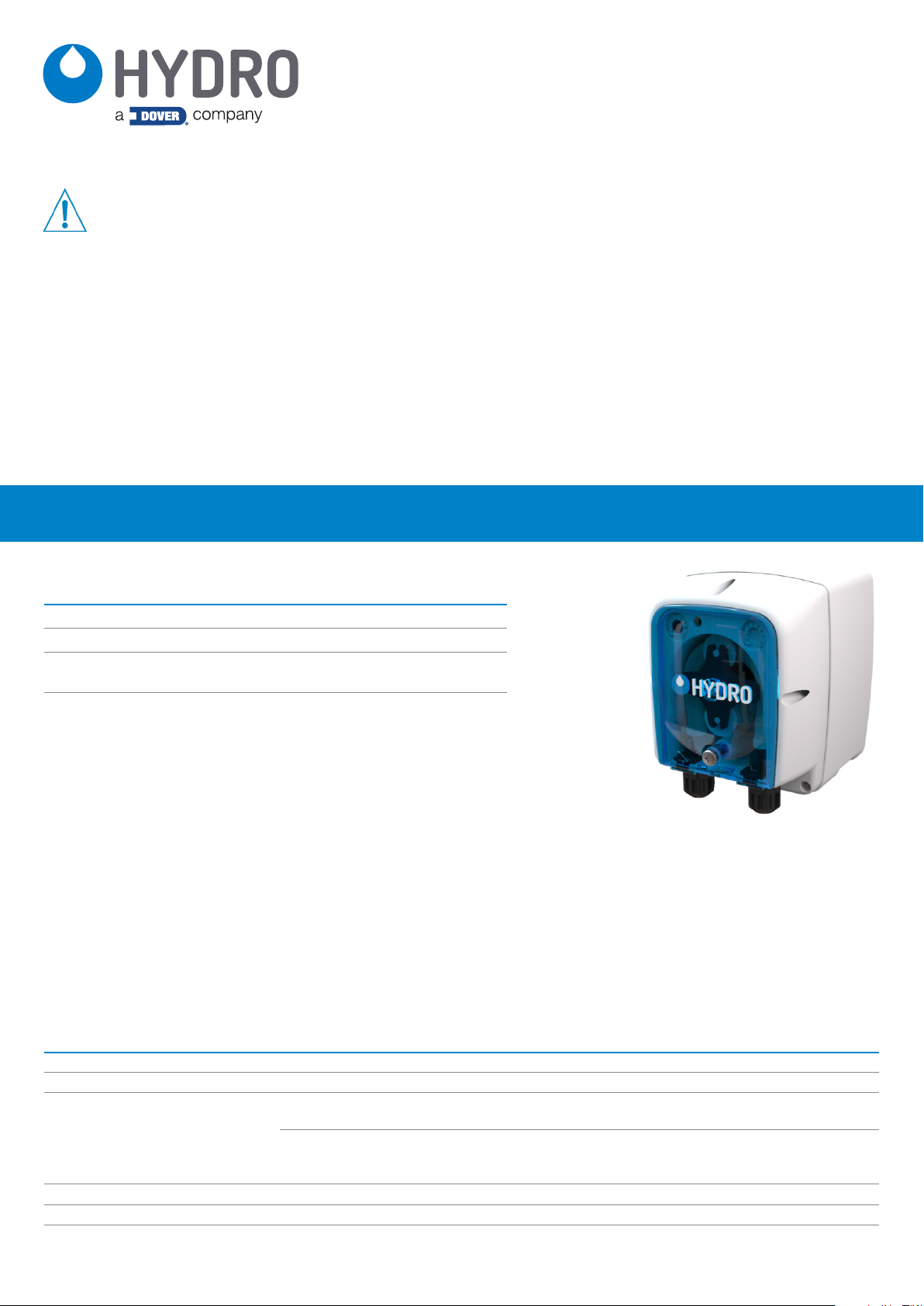
CP-5OO Warewash Dispenser
Please read precautions thoroughly before operation. Meet all applicable local codes and regulations.
THANK YOU FOR YOUR INTEREST IN OUR PRODUCTS
Please use this equipment carefully and observe all warnings and cautions.
WEAR
ALWAYS
KEEP
protective clothing and eyewear when dispensing chemicals or other materials or when working in the vicinity
of all chemicals, filling or emptying equipment, or changing metering tips.
observe safety and handling instructions of the chemical manufacturer.
direct discharge away from you or other persons or into approved containers.
dispense cleaners and chemicals in accordance with manufacturer’s instructions. Exercise CAUTION when
maintaining your equipment.
reassemble equipment according to instruction procedures. Be sure all components are firmly screwed or
latched into position.
equipment clean to maintain proper operation.
introduction
Package Contents
CP-500 Warewash Dispenser (part number varies by model)
• CP-500 Dispenser (Part number varies by model)
• Quick Start Guide (P/N HYD10099215)
• Accessory Kit: Mounting bracket, fittings, hardware, and pickup tubing
(Part number varies by model)
• Pump Squeeze Tube (not installed)
• Detergent models use Santoprene® tubes as standard
• Rinse models use silicone tubes as standard
• (Part number varies by model)
Operation
The CP-500 is a globally versatile, single product dispenser used to supply detergents or rinse aid into automatic dish machines. Designed
with simplicity in mind, the unit can be installed in minutes and requires no programming; all settings can be configured using potentiometers
that control the time or speed of dosing (depending on the model). The unit has the reliability and accuracy you expect from Hydro Systems
Co. at an economic price point.
NOTE! The CP-500 is intended for use in industrial applications. It is not suitable for domestic use, and it must not be used outside of its
intended use. The product must only be used for commercial dish washing operations. The manufacturer waives any responsibility arising
from incorrect usage or transportation.
General Specifications
Category Specification
Electrical 90 to 260 VAC at 50/60Hz
Chemical Temperature Rating Intake chemicals should be at room temperature
Regulatory Approvals (CE) 89/336/CEE
73/23/CEE
Cabinet Material Front: Polypropylene - Rear: Polypropylene
Environmental Pollution: Degree 2, Temperature: 50°to 104° F (10° to 40° C), Maximum Humidity: 95% Relative
Dimensions 5.0 in (128 mm) High x 3.6 in (91 mm) Wide x 4.1 in (104 mm) Depth
(Regarding “Electromagnetic Compatibility” and the subsequent
modifications to 92/31/CEE, 93/68/CEE, 93/97/CEE)
(Regarding “Low Voltages”, and the subsequent modifications to
93/68/CEE, 2002/95/CE, 2002/96/CE, 2003/108/CE “RoHs and
WEEE Directive”)
Page 2

installation
Wall Mount
1. Choose an installation location that is:
• Within 1.5m (4.5 ft.) of the product containers.
• At a reasonable height above the wash tank on the dish machine that allows for easy maintenance access.
• Away from any direct sources of steam, water spray, and high temperatures.
• Close enough to the dish machine electrical control panel to allow dispenser wiring without use of an external junction box (not
provided) wherever possible.
2. Use the mounting bracket to mark the appropriate mounting location and as a hole template to mark the securing holes.
3. Wall anchors are provided, please ensure they are appropriate to the wall/surface being mounted to.
4. Attach mounting bracket to mounting surface with hardware provided.
5. Hang unit on bracket.
Installing the Rinse Injection Fitting
1. Install the rinse injection fitting to conform to local plumbing codes.
2. The injection fitting is designed to fit global needs. It should thread directly into a 1/8” NPT (North America) or a BSP (Global) female
threaded connection. As an alternative to the threaded connection a barb fitting adapter is also included.
3. If the machine’s rinse plumbing is thin-wall pipe, use a saddle clamp with the 1/8” threaded hole.
4. If the machine already has a tapped hole to accommodate the fitting, skip to Step 8
5. Choose a location for the rinse injection fitting that is downstream from the vacuum breaker and at the proper height per local plumbing
codes. This point is either into the pressurized rinse line or upstream of the booster heater for the rinse water.
6. To create the threaded connection at your selected location, drill a 9 mm (11/32”) hole in the rinse plumbing at the injection location.
7. Tap the hole drilled in step 6 with a 1/8” tap (NPT or BSP depending on the region)
8. Install the injection fitting. Use thread sealant to ensure a leak-free assembly.
Installing the Detergent Injection Fitting
1. When choosing a mounting locating, make sure that the detergent infection fitting will be:
• Above the water level of the filled wash tank.
• Discharging detergent directly into the wash tank and not on top of any shelf areas or other obstacles that could prevent
detergent from falling directly into the wash tank.
2. Previously punched holes may be suitable but always confirm that the fitting is correctly placed. 10mm (3/8’’) holes are common in
Europe and 22mm (7/8’’) holes are common in North America. If an appropriate hole is present, go to step 4.
3. If a hole is not available already, drill a 10mm (3/8’’) hole at the center of your chosen detergent injection location on the dish machine
tank.
4. Remove the retaining nut from the supplied detergent injection fitting and gather the gaskets and washers supplied with the unit.
5. a. For a 10mm (3/8’’) hole insert the detergent injection fitting (with a rubber gasket) into the hole you drilled earlier.
b. For a 22mm (7/8’’) hole insert the detergent injection fitting (with a large rubber gasket backed by a large stainless steel washer).
6. From the inside of the machine install a second rubber washer, stainless backing washer if using a 22mm (7/8’’) hole, and the retaining
nut. Tighten finger-tight, then snug using a wrench.
CAUTION! Do not over-tighten the plastic retaining nut.
Page 3

installation (continued)
Installing the Rinse and Detergent Supply and Discharge Tubes
1. Install the included PVC pump supply tube (4mm ID, 6mm OD) into the chemical container using the foot filter with screen and weight to
position the tube at the bottom of the container.
2. Route the other end of the included PVC pump supply tubes from supply containers to the inlet sides (left) of each respective pump. Slip
the tube fully through the compression nut into fitting and tighten.
3. Route pump discharge tubes to the outlet sides (right) of each respective pump. Slip the tube fully through compression nut into fitting
and tighten.
4. Route the other end the pump discharge tube to the appropriate injection fitting (see injection fitting installation instructions on previous
page for more detail). Slip the tube fully through the compression nut onto fitting nipple and tighten.
NOTE: Try to keep both the supply and discharge hoses as straight as possible, avoiding all unnecessary bends.
WARNING! Before any work on the CP-500, you must disconnect the power supply voltage of the dish machine.
Installing the Detergent and Rinse Supply Signal Wiring
CAUTION! Verify that electrical grounding is functional and complies with local regulations. Verify that the rated values of the pump
are compatible with those of the power supply. Never install the pump directly in parallel with inductive loads (e.g. motors/solenoid
valves). If necessary, use an isolating relay.
NOTE: All electrical connections must either be in the dish machine control circuit panel or an external junction box. The dispenser is prewired with a multi-conductor electrical cable that may need to be run through a conduit to the location where hard-wired connections are
made on the dish machine. If this is the case use approved water tight conduit that meets local and national codes.
Depending on the model of the CP-500, there will be one or two pairs of signal/power wires that need to be connected to the dish machine.
Connect the signal wires to a compatible voltage source.
Detergent Pumps - Signal Wiring and Programming
Model D1TT - Dish Machine with One Solenoid
Connect the signal cable to the solenoid valve for top up/rinse.
When the signal is activated, the pump will run for the time programmed (0 to 30 seconds) on the upper left top-up dose potentiometer. If the
signal stops before the time setting is reached, the pump will stop.
If the signal is still active after 30 seconds, the pump will then run (or continue to run) using the setting (0-240 sec) of the upper right initial
charge potentiometer.
Because the pump always runs the Top-up dose and runs it before the Initial Charge, you do not set the Initial Charge to the full value you
need, but to that full value minus the Top-up dose time.
Example: If you need an Initial Charge of 70 seconds, and your Top-up dose is set to 15 seconds, then you actually set the Initial Charge
potentiometer to 55 seconds. (70 - 15 = 55)
CAUTION! Notice the setting potentiometers are reversed in position from the D1TT to the D2TT.
Model D2TT - Dish Machine with Two Solenoids
Connect the Top-up signal cable to the solenoid valve for top-up/rinse.
When the top-up signal activates the pump will run (at full speed) for the time programmed (0 to 30 seconds) on the upper right top-up dose
potentiometer. If the signal stops before the time setting is reached, the pump will stop.
Connect the Fill/Initial Charge signal cable to the fill solenoid.
When the fill signal activates, the pump runs (at full speed) for the time programmed (0 to 240 seconds) on the upper left initial charge
potentiometer. If the signal stops before the time setting is reached, the pump will stop.
Rinse Pumps - Signal Wiring and Programming
Model R1ST - Dish Machine with One Solenoid
Connect the signal cable to the solenoid valve for the rinse water.
Page 4

installation (continued)
Rinse Pumps - Signal Wiring and Programming (continued)
Speed Setting
The pump runs at the speed set using the left potentiometer.
• Minimum speed (completely turned counterclockwise): 10%
• Maximum speed (completely turned clockwise): 100%
The speed setting is also indicated by flashing the green LED, proportional to the set speed. For example:
10% = 5 seconds ON / 5 seconds OFF = one flash per 10 seconds
50% = 1 second ON / 1 second OFF = five flashes per 10 seconds
100%= 0.5 second ON / 0.5 second OFF = ten flashes per 10 seconds
Run/Shut-off Time Setting
Use the right potentiometer to set the rinse pump run/shut-off time.
If you want the pump to run continuously as long as the rinse signal is active, turn the potentiometer completely counterclockwise. To limit the
duration that the pump runs turn the potentiometer clockwise to adjust from 1 to 240 seconds (as shown to the right).
When adjusting the right potentiometer, turn slowly clockwise while watching the LED to help set the correct run/shut-off time. The pump
displays four setting positions by flashing the LED:
In the position between 60 and 90 seconds the LED will flash red once
In the position between 90 and 120 seconds the LED will flash red twice
In the position between 120 and 180 seconds the LED will flash red 3 times
In the position between 180 and 240 seconds the LED will flash red 4 times
Model R1S - Dish Machine with Two Solenoids
Connect the signal cable to the solenoid valve for the rinse water.
Speed Setting
The pump runs at the speed set using the left potentiometer.
• Minimum speed (completely turned counterclockwise): 10%
• Maximum speed (completely turned clockwise): 100%
The speed setting is also indicated by flashing the green LED, proportional to the set speed. For example:
10% = 5 seconds ON / 5 seconds OFF = one flash per 10 seconds
50% = 1 second ON / 1 second OFF = five flashes per 10 seconds
100% = 0.5 second ON / 0.5 second OFF = ten flashes per 10 seconds
operation
The CP-500 makes use of 1 or 2 potentiometers for setting run times and/or speed, a power/prime switch, and a multi-color LED for
indicating the dispenser status. The power/prime switch and LED status indications are described below.
Power/Prime Switch Operation
Found on the bottom of pump body, the switch has 3 positions:
I: The pump is active (ON). The pump will run normally. If no signal is present, the LED will be off.
O: The pump is in stand-by (OFF). The LED will be fixed red.
II: The pump is in priming mode. The LED will be fixed orange
The II priming position of the switch is “momentary”, but the pump runs at full speed for 60 seconds. If the II position is pressed again before
60 seconds have elapsed the pump will stop and the switch will return to the stand-by position.
Hydro Systems Company
Americas +1 513-271-88OO contact-hydro@hydrosystemsco.com www.hydrosystemsco.com
Europe +44 O1344 48888O info@hydrosystemseurope.com www.hydrosystemseurope.com
Asia Pacific +86 21-6O81-2888 sales.hydro@hydrosystemschina.com www.hydrosystemschina.com
HYD1OO99215 Rev A 04/19
Page 5
guide de démarrage rapide
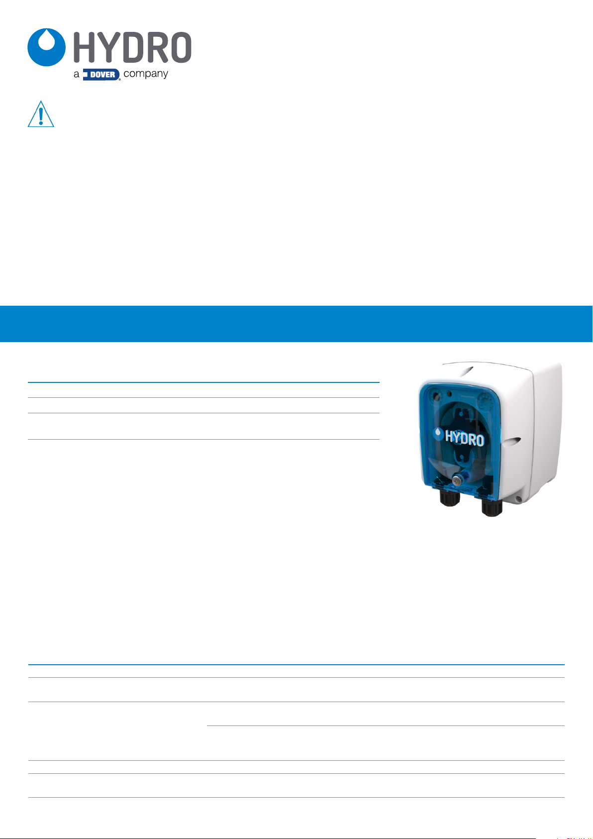
Distributeur de détergent industriel CP-500
MISE EN
GARDE
PORTER
TOUJOURS
GARDER
Prière de lire attentivement ces consignes avant le fonctionnement. Tous les règlements et codes locaux en
vigueur doivent être suivis.
MERCI DE VOTRE INTÉRÊT POUR NOS PRODUITS
Veuillez utiliser cet équipement avec soin et respecter tous les avertissements et mises en garde.
des vêtements et des lunettes de protection lors de la distribution de produits chimiques ou d’autres matériels
ou lors de travaux à proximité de tous les produits chimiques, équipement de remplissage ou de vidange, ou
changement des pointes de dosage.
respecter les consignes de sécurité et de manutention des fabricants des substances chimiques.
diriger la vidange hors de sa portée ou de la portée des personnes ou dans des contenants agréés.
éliminer les détergents et les substances chimiques conformément aux instructions du fabricant. Faire
ATTENTION lors de l’entretien de l’équipement.
remonter l’appareil conformément aux procédures du mode d’emploi. S’assurer que tous les composants sont
solidement vissés ou verrouillés en position.
l’appareil dans un état propre pour assurer un fonctionnement approprié.
introduction
Contenu du paquet
Distributeur de détergent industriel CP-500 (le code d’article varie en fonction du modèle)
• Distributeur CP-500 (Le code d’article varie en fonction du modèle)
• Guide de démarrage rapide (P/N HYD10099215)
• Kit d’accessoires : Support de fixation, raccords, matériel informatique et tuyauterie de
collecte (Le code d’article varie en fonction du modèle)
• Tuyau de remplissage de la pompe (pas installé)
• Les modèles à détergent utilisent des tuyaux en Santoprene® comme standard
• Les modèles de rinçage utilisent des tuyaux en silicone comme standard
• (Le code d’article varie en fonction du modèle)
Fonctionnement
Le distributeur CP-500 est un modèle polyvalent qui distribue des produits individuels pour alimenter les lave-vaisselle automatiques en
détergent ou produit de rinçage. Conçu dans un souci de simplicité, l’appareil peut être installé en quelques minutes et ne nécessite aucune
programmation ; tous les réglages peuvent être configurés à l’aide de potentiomètres contrôlant le temps ou la vitesse de dosage (en fonction
du modèle). Cet appareil a la fiabilité et la précision habituelles des produits Hydro Systems Co. à un prix économique.
NOTE ! CP-500 est prévu pour une utilisation dans des applications industrielles. Il ne convient pas à un usage domestique et ne doit pas
être utilisé en dehors de son utilisation prévue. Le produit ne doit être utilisé que pour des opérations commerciales de lavage de la vaisselle.
Le fabricant se dégage de toute responsabilité découlant d’une utilisation ou d’un transport incorrect.
Généralités
Catégorie Spécification
Électrique 90 à 260 VAC à 50/60 Hz
Température nominale des substances
chimiques
Homologations (CE) 89/336/CEE
Matériau de l’armoire Façade : Polypropylène - Dos : Polypropylène
Environnement
Dimensions 5,0 in (128 mm) hauteur x 3,6 in (91 mm) largeur x 4,1 in (104 mm) profondeur
Les produits chimiques alimentés doivent être à température ambiante
(Concernant la « Compatibilité électromagnétique » et amendements
et modifications successives à 92/31/CEE, 93/68/CEE, 93/97/CEE)
(Concernant la « Basse Tension » et amendements et modifications
73/23/CEE
Pollution : Indice 2, Température : 50° à 104 °F (10° à 40 °C), Humidité maximale : 95 %
relative
successives à 93/68/CEE, 2002/95/CE, 2002/96/CE, 2003/108/CE
« Directive RoHs et DEEE »)
Page 6

installation
Montage mural
1. Choisir un endroit pour l’installation :
• À 1,5 m (4,5 ft) maximum des réservoirs de produits.
• À une hauteur raisonnable au-dessus de la cuve de lavage du lave-vaisselle pour permettre un accès aisé pour l’entretien.
• Éloigné des sources directes de vapeur, de pulvérisation d’eau et de chaleur élevée.
• Assez proche du panneau de commande du lave-vaisselle pour permettre le branchement direct du doseur sans boîtier de
raccordement (non fourni), si possible.
2. Utiliser le support de fixation pour tracer l’emplacement approprié de montage et comme gabarit de perçage pour repérer les trous de
fixation.
3. Des ancrages muraux sont fournis, s’assurer qu’ils conviennent pour le montage sur le mur ou la surface prévue.
4. Poser le support de fixation sur la surface choisie au moyen du matériel fourni.
5. Fixer l’appareil sur le support.
Installation du raccord d’injection de rinçage
1. Poser le raccord d’injection de rinçage conformément aux normes locales de plomberie.
2. Le raccord d’injection est conçu pour répondre aux exigences universelles. Il doit être enfilé directement dans un raccord fileté femelle
1/8” NPT (Amérique du Nord) ou BSP (global). Comme alternative à la connexion filetée, un adaptateur pour raccord cannelé est
également inclus.
3. Si la tuyauterie du lave-vaisselle est à paroi mince, utiliser un collier de tuyau avec un trou fileté 1/8”.
4. Si la machine dispose déjà d’un orifice taraudé adapté au raccord, passer à l’étape 8.
5. Choisir un endroit où poser le raccord de l’injection de rinçage qui se trouve en aval du casse-vide et à une hauteur adaptée selon les
normes locales de plomberie. Ce point se trouve soit dans la conduite de rinçage sous pression, soit en amont du surchauffeur pour
l’eau de rinçage.
6. Pour créer la connexion filetée à l’emplacement choisi, percer un trou de 9 mm (11/32”) dans la plomberie de rinçage au point d’injection.
7. Taper sur le trou foré à l’étape 6 avec un taraud 1/8 ”(NPT ou BSP selon la région).
8. Poser le raccord d’injection. Utiliser un produit d’étanchéité pour filetages pour garantir l’absence de fuites dans l’installation.
Installation du raccord d’injection du détergent
1. Lors du choix de l’emplacement de montage, vérifier que le raccord d’injection du détergent :
• Se trouve au-dessus du niveau de l’eau de la cuve de lavage pleine.
• Envoie le détergent directement dans la cuve de lavage et pas au-dessus des clayettes ou d’autres obstacles qui pourraient
empêcher l’arrivée directe du détergent dans la cuve de lavage.
2. Les trous déjà présents peuvent être utilisés à condition de toujours s’assurer que le raccord est placé correctement. Les trous de
10 mm (3/8”) sont courants en Europe et les trous de 22 mm (7/8”) sont courants en Amérique du Nord. Si un trou approprié est présent,
passer à l’étape 4.
3. Si aucun trou n’est déjà disponible, percer un trou de 10 mm (3/8”) au centre de l’emplacement d’injection de détergent choisi sur la
cuve du lave-vaisselle.
4. Retirer l’écrou de retenue du raccord d’injection de détergent fourni et rassembler les joints et les rondelles fournis avec l’appareil.
5. a. Pour un trou de 10 mm (3/8”), insérer le raccord d’injection de détergent (avec un joint en caoutchouc) dans le trou qui vient d’être
percé.
b. Pour un trou de 22 mm (7/8”), insérer le raccord d’injection de détergent (avec un grand joint en caoutchouc renforcé par une grande
rondelle en acier inoxydable).
6. Depuis l’intérieur de la machine, installer une deuxième rondelle en caoutchouc, une rondelle en acier inoxydable si on utilise un trou de
22 mm (7/8”) et l’écrou de retenue. Serrer d’abord à la main, puis avec une clé.
ATTENTION ! Ne pas trop serrer l’écrou de retenue en plastique.
Page 7

installation (suite)
Installation des tuyaux d’arrivée et d’évacuation du rinçage et du détergent
1. Installer le tuyau d’alimentation de la pompe en PVC fourni (diamètre intérieur 4 mm, diamètre extérieur 6 mm) à l’aide du filtre à pied
avec écran et lui appliquer un poids pour positionner le tuyau au fond du réservoir.
2. Diriger l’autre extrémité des tuyaux d’arrivée des pompes en PVC depuis les réservoirs d’alimentation vers les entrées (à gauche) de
chaque pompe. Faire glisser l’intégralité du tuyau par l’écrou de compression dans le raccord et serrer.
3. Diriger les tuyaux d’évacuation des pompes vers les sorties (à droite) de chaque pompe. Faire glisser l’intégralité du tuyau par l’écrou de
compression dans le raccord et serrer.
4. Diriger l’autre extrémité du tuyau d’évacuation de la pompe vers le raccord d’injection approprié (voir les instructions d’installation du
raccord d’injection à la page précédente pour plus de détails). Faire glisser l’intégralité du tuyau par l’écrou de compression sur le
mamelon de raccord et serrer.
REMARQUE : Essayer de garder les flexibles d’alimentation et d’évacuation aussi droits que possible, en évitant les coudes inutiles.
MISE EN GARDE ! Avant de travailler sur le dispositif CP-500, débrancher l’alimentation électrique du lave-vaisselle.
Installation du câblage du signal d’alimentation du détergent et du rinçage
ATTENTION ! Vérifier que la mise à la terre électrique est fonctionnelle et conforme aux réglementations locales. Vérifier que
les valeurs nominales de la pompe sont compatibles avec celles de l’alimentation. Ne jamais installer la pompe directement en
parallèle avec des charges inductives (par exemple, moteurs/électrovannes). Si nécessaire, utiliser un relais d’isolement.
REMARQUE : Tous les branchements électriques se font soit sur le panneau du circuit imprimé du lave-vaisselle soit sur un boîtier externe.
Le doseur est précâblé au moyen d’un câble électrique multiconducteur qui doit être placé dans un conduit et mené aux branchements du
lave-vaisselle. Si tel est le cas, utiliser un conduit étanche conforme aux normes locales et nationales.
Selon le modèle du dispositif CP-500, une ou deux paires de câbles de signal/alimentation doivent être connectées au lave-vaisselle.
Connecter les fils de signal à une source de tension compatible.
Pompes à détergent - Câblage et programmation du signal
Modèle D1TT - Lave-vaisselle à un solénoïde
Brancher le câble de signal à l’électrovanne pour le complément/rinçage.
Lorsque le signal est activé, la pompe fonctionnera pendant le temps programmé (0 à 30 secondes) sur le potentiomètre de dose
complémentaire supérieur gauche. Si le signal s’arrête avant que l’heure configurée ne soit atteinte, la pompe s’arrête.
Si le signal est toujours actif après 30 secondes, la pompe fonctionnera (ou continuera à fonctionner) en utilisant le réglage (0-240 s) du
potentiomètre de charge initiale supérieur droit.
Étant donné que la pompe utilise toujours la Dose Complémentaire et l’envoie avant la Charge Initiale, on ne définit pas la Charge Initiale sur
la valeur complète dont on a besoin, mais sur cette valeur complète moins le temps de Dose Complémentaire.
Par exemple : S’il faut une Charge Initiale de 70 secondes et que la Dose Complémentaire est définie sur 15 secondes, on règle en fait le
potentiomètre de Charge Initiale sur 55 secondes. (70 - 15 = 55).
ATTENTION ! Il convient de remarquer que les potentiomètres de réglage sont inversés de la position D1TT à la D2TT.
Modèle D2TT - Lave-vaisselle à deux solénoïdes
Brancher le câble de signal du complément à l’électrovanne pour le complément/rinçage.
Lorsque le signal du complément est activé, la pompe fonctionnera (à pleine vitesse) pendant le temps programmé (0 à 30 secondes) sur le
potentiomètre de dose complémentaire supérieur droit. Si le signal s’arrête avant que l’heure configurée ne soit atteinte, la pompe s’arrête.
Brancher le câble de signal de Remplissage/Charge Initiale au solénoïde de remplissage.
Lorsque le signal du remplissage est activé, la pompe fonctionnera (à pleine vitesse) pendant le temps programmé (0 à 240 secondes) sur le
potentiomètre de charge initiale supérieur gauche. Si le signal s’arrête avant que l’heure configurée ne soit atteinte, la pompe s’arrête.
Pompes de rinçage - Câblage et programmation du signal
Modèle R1ST - Lave-vaisselle à un solénoïde
Brancher le câble de signal à l’électrovanne pour l’eau de rinçage.
Page 8

installation (suite)
Pompes de rinçage - Câblage et programmation du signal (suite)
Réglage de vitesse
La pompe fonctionne à la vitesse configurée à l’aide du potentiomètre gauche.
• Vitesse minimum (complètement tourné en sens antihoraire) : 10 %
• Vitesse maximum (complètement tourné en sens horaire) : 100 %
Le réglage de vitesse est également indiqué par le clignotement de la LED verte, proportionnelle à la vitesse configurée.
Par exemple :
10 % = 5 secondes allumée / 5 secondes éteinte = un clignotement toutes les 10 secondes
50 % = 1 seconde allumée / 1 seconde éteinte = cinq clignotements toutes les 10 secondes
100 % = 0,5 seconde allumée / 0,5 seconde éteinte = dix clignotements toutes les 10 secondes
Configuration du temps de marche/arrêt
Utiliser le potentiomètre droit pour régler le temps de marche/arrêt de la pompe de rinçage.
Pour que la pompe fonctionne en continu tant que le signal de rinçage est actif, tourner le potentiomètre complètement dans le sens
antihoraire. Pour limiter la durée de fonctionnement de la pompe, tourner le potentiomètre en sens horaire pour régler de 1 à 240 secondes
(comme indiqué à droite).
Lors du réglage du potentiomètre droit, tourner lentement en sens horaire tout en regardant la LED pour s’aider à régler le bon temps de
marche/arrêt. La pompe affiche quatre positions de réglage en faisant clignoter la LED :
Entre 60 et 90 secondes, la LED clignote une fois en rouge
Entre 90 et 120 secondes, la LED clignote deux fois en rouge
Entre 120 et 180 secondes, la LED clignote trois fois en rouge
Entre 180 et 240 secondes, la LED clignote quatre fois en rouge
Modèle R1S - Lave-vaisselle à deux solénoïdes
Brancher le câble de signal à l’électrovanne pour l’eau de rinçage.
Réglage de vitesse
La pompe fonctionne à la vitesse configurée à l’aide du potentiomètre gauche.
• Vitesse minimum (complètement tourné en sens antihoraire) : 10 %
• Vitesse maximum (complètement tourné en sens horaire) : 100 %
Le réglage de vitesse est également indiqué par le clignotement de la LED verte, proportionnelle à la vitesse configurée. Par exemple :
10 % = 5 secondes allumée / 5 secondes éteinte = un clignotement toutes les 10 secondes
50 % = 1 seconde allumée / 1 seconde éteinte = cinq clignotements toutes les 10 secondes
100 % = 0,5 seconde allumée / 0,5 seconde éteinte = dix clignotements toutes les 10 secondes
fonctionnement
Le dispositif CP-500 utilise 1 ou 2 potentiomètres pour régler les temps de fonctionnement et/ou la vitesse, un commutateur d’alimentation/
amorçage et une LED multicolore pour indiquer l’état du distributeur. L’interrupteur d’alimentation/amorçage et les LED d’état sont décrits
ci-dessous.
Fonctionnement de l’interrupteur d’alimentation/amorçage
Situé au bas du corps de la pompe, l’interrupteur a 3 positions :
I : La pompe est active (ON). La pompe fonctionnera normalement. Si aucun signal n’est présent, la LED sera éteinte.
O : la pompe est en veille (OFF). La LED sera fixe en rouge.
II : La pompe est en mode d’amorçage. La LED sera fixe en orange.
La position d’amorçage II de l’interrupteur est « momentanée », mais la pompe fonctionne à pleine vitesse pendant 60 secondes. Si on
appuie à nouveau sur la position II avant que 60 secondes se soient écoulées, la pompe s’arrête et l’interrupteur revient en position d’attente.
Hydro Systems Company
Americas +1 513-271-88OO contact-hydro@hydrosystemsco.com www.hydrosystemsco.com
Europe +44 O1344 48888O info@hydrosystemseurope.com www.hydrosystemseurope.com
Asia Pacific +86 21-6O81-2888 sales.hydro@hydrosystemschina.com www.hydrosystemschina.com
HYD1OO99215 Rev A 04/19
Page 9

Kurzanleitung
Dosierer CP-5OO für Geschirrspüler
WARNUNG
TRAGEN SIE
IMMER
HALTEN SIE
Bitte vor Inbetriebnahme sorgfältig durchlesen. Es sind alle lokalen Vorschriften und Regeln zu beachten.
VIELEN DANK FÜR DAS VERTRAUEN IN UNSERE PRODUKTE
Dieses Gerät bitte mit Vorsicht und unter Berücksichtigung aller Warnhinweise einsetzen.
Schutzkleidung und Brille bei der Ausgabe von Chemikalien oder anderen Materialien oder bei der Arbeit in der
Nähe aller Chemikalien, beim Befüllen oder Entleeren von Geräten oder beim Wechseln der Dosierspitzen.
Die Sicherheits- und Handhabungshinweise des Herstellers der Chemikalie berücksichtigen.
Das Ablassen und Weggießen vom Körper weg und nicht in Richtung anderer Personen bzw. in entsprechende
Behälter vornehmen.
Reinigungsmittel und Chemikalien entsprechend den Herstelleranweisungen dosieren. Bei Instandhaltung der
Ausrüstung VORSICHTIG vorgehen.
Die Ausrüstung den Verfahrensanweisungen entsprechend wieder zusammenbauen. Sicherstellen, dass alle
Bauteile fest verschraubt oder in ihrem Sitz eingerastet sind.
Die Ausrüstung sauber, um einen ordnungsgemäßen Betrieb zu gewährleisten.
einleitung
Inhalt der Verpackung
Dosierer für Geschirrspüler CP-500 (Teilenummer je nach Modell unterschiedlich)
• Dosiersystem CP-500
• (Teilenummer je nach Modell unterschiedlich)
• Kurzanleitung (P/N HYD10099215)
• Zubehörsatz: Halterung, Anschlussstücke, Befestigungselemente und
Ansaugschläuche (Teilenummer je nach Modell unterschiedlich)
• Quetschschlauch für Pumpe (nicht installiert)
• Bei Modellen für Spülmittel standardmäßig Schläuche aus Santoprene®
• Bei Modellen für Klarspüler standardmäßig Schläuche aus Silikon
• (Teilenummer je nach Modell unterschiedlich)
Betrieb
Der CP-500 ist ein sehr vielseitiger Dosierer für ein einzelnes Produkt, der für die Zuführung von Spülmittel oder Klarspüler in automatische
Geschirrspüler vorgesehen ist. Das auf hohe Benutzerfreundlichkeit ausgelegte Gerät kann in wenigen Minuten installiert werden und braucht
nicht programmiert zu werden. Alle Einstellungen können über Potentiometer vorgenommen werden, die (je nach Modell) die Dosierdauer
oder -geschwindigkeit steuern. Das Gerät bietet die Zuverlässigkeit und Genauigkeit, die Sie von Hydro Systems Co. erwarten, zu einem
günstigen Preis.
HINWEIS! Der CP-500 wurde für industrielle Anwendungen konzipiert. Es ist nicht für einen Einsatz im Haushalt geeignet und darf
ausschließlich für den vorgesehenen Verwendungszweck eingesetzt werden. Das Produkt darf nur zum Geschirrspülen im gewerblichen
Bereich eingesetzt werden. Im Falle von unsachgemäßem Einsatz oder Transport lehnt der Hersteller jegliche Haftung ab.
Allgemeine technische Angaben
Kategorie Spezifikation
Elektrik 90 bis 260 V AC bei 50/60 Hz
Temperatur der Chemikalien Die angesaugten Chemikalien sollten Raumtemperatur haben.
Zulassungen (CE) 89/336/EWG
73/23/EWG
Gehäusematerial Vorderseite: Polypropylen - Rückseite: Polypropylen
Umgebung
Abmessungen 5.0 in (128 mm) Höhe x 3.6 in (91 mm) Breite x 4.1 in (104 mm) Tiefe
Verschmutzungsgrad: 2, Temperatur: 50 bis 104 °F (10 bis 40 °C), Maximale Luftfeuchtigkeit: 95 %
relative Lf
(über die „Elektromagnetische Verträglichkeit“ und nachfolgende
Änderungen nach 92/31/EWG, 93/68/EWG, 93/97/EWG)
(über „Niederspannung“ und nachfolgende Änderungen nach 93/68/EWG,
2002/95/EG, 2002/96/EG, 2003/108/EG „RoHs- und WEEE-Richtlinine“)
Page 10

installation
Wandmontage
1. Einen Installationsort suchen, der folgende Bedingungen erfüllt:
• Im Abstand von höchstens 1,5 m (4.5 ft.) von den Produktbehältern.
• In ausreichender Höhe über dem Waschtank des Geschirrspülers, damit der Zugang für die Wartung leicht möglich ist.
• In ausreichendem Abstand von Dampf-, Wassernebel- und Wärmequellen.
• Nah genug an der elektrischen Steuerkonsole des Geschirrspülers, dass der Dosierer möglichst ohne externe Anschlussdose (nicht
mitgeliefert) damit verdrahtet werden kann.
2. Unter Verwendung der Wandhalterung als Schablone die richtige Anbringungsstelle markieren und die Bohrlöcher an der Wand
anzeichnen.
3. Wanddübel sind im Lieferumfang enthalten. Bitte überprüfen, ob sie für die Art der Wand/Oberfläche, an der die Einheit montiert werden
soll, geeignet sind.
4. Die Halterung mit den mitgelieferten Befestigungselementen an der Montagefläche befestigen.
5. Das Gerät in die Halterung einhängen.
Installation der Klarspülereinspritzung
1. Die Klarspülereinspritzung so installieren, dass sie den örtlichen Vorschriften zur Rohrverlegung entspricht.
2. Die Klarspülereinspritzung ist für weltweite Nutzung ausgelegt. Es sollte direkt in einen 1/8” NPT- (Nordamerika) oder BSPAußengewindeanschluss (weltweit) eingeschraubt werden. Als Alternative zum Gewindeanschluss ist auch ein Schlauchtüllen-Adapter
enthalten.
3. Wenn die Klarspülschläuche des Geschirrspülers dünnwandig sind, benutzen Sie eine Sattelklemme an der 1/8”-Gewindebohrung.
4. Wenn der Geschirrspüler bereits eine Gewindebohrung zur Aufnahme des Anschlusses hat, mit Schritt 8 fortfahren.
5. Für die Klarspülereinspritzung eine Stelle hinter dem Vakuumschalter und in der richtigen Höhe gemäß den örtlichen Vorschriften zur
Rohrverlegung suchen. Diese Stelle befindet sich entweder in der druckbeaufschlagten Spülleitung oder vor der Zusatzheizung für das
Spülwasser.
6. Um an der ausgewählten Stelle einen Gewindeanschluss zu schaffen, an der Einspritzstelle ein 9 mm (11/32”) großes Loch in die
Spülleitung bohren.
7. In das in Schritt 6 gebohrte Loch ein 1/8”-Gewinde schneiden (je nach Region NPT oder BSP).
8. Die Klarspülereinspritzung installieren. Benutzen Sie Gewindedichtungsmittel, um einen leckfreien Zusammenbau sicherzustellen.
Installation der Spülmitteleinspritzung
1. Bei der Auswahl der Installationsstelle sicherstellen, dass die Spülmitteleinspritzung:
• über dem Wasserpegel des gefüllten Waschtanks liegt.
• das Spülmittel direkt in den Waschtank abgibt und nicht auf Randbereiche oder Hindernisse, die verhindern könnten, dass das
Spülmittel direkt in den Waschtank gelangt.
2. Bereits vorhandene Bohrungen können geeignet sein, aber vergewissern Sie sich immer, ob der Anschluss richtig platziert ist. In Europa
sind Bohrungen mit 10 mm (3/8’’) Durchmesser üblich, in Nordamerika Bohrungen mit 22 mm (7/8’’) Durchmesser. Falls bereits eine
geeignete Bohrung vorhanden ist, mit Schritt 4 fortfahren.
3. Falls noch keine Bohrung vorhanden ist, in der Mitte der gewählten Stelle für die Spülmitteleinspritzung am Tank des Geschirrspülers ein
Loch mit 10 mm (3/8’’) Durchmesser bohren.
4. Die Sicherungsmutter von der mitgelieferten Spülmitteleinspritzung entfernen und die mit dem Gerät gelieferten Dichtungen und
Unterlegscheiben aufnehmen.
5. a. Bei einer 10 mm (3/8’’)-Bohrung die Spülmitteleinspritzung (zusammen mit einer Gummidichtung) in das zuvor gebohrte Loch einsetzen.
b. Bei einer 22 mm (7/8’’)-Bohrung die Spülmitteleinspritzung (zusammen mit einer großen Gummidichtung und einer großen EdelstahlUnterlegscheibe) einsetzen.
6. Von der Innenseite des Geschirrspülers aus eine zweite Gummiunterlegscheibe, bei einer 22 mm (7/8’’)-Bohrung eine weitere
Edelstahl-Unterlegscheibe, und die Sicherungsmutter anbringen. Die Mutter zunächst von Hand festschrauben und dann mit einem
Schraubenschlüssel anziehen.
VORSICHT! Die Kunststoff-Sicherungsmutter nicht zu fest anziehen.
Page 11

installation (fortsetzung)
Installation der Zufuhr- und Abgabeschläuche für Spülmittel und Klarspüler
1. Den mitgelieferten PVC-Zufuhrschlauch (NW 4 mm, AD 6 mm) der Pumpe mit dem Fußfilter mit Sieb und dem Gewicht, damit der
Schlauch auf dem Behälterboden bleibt, in den Chemikalienbehälter einführen.
2. Das andere Ende der mitgelieferten PVC-Zufuhrschläuche von den Chemikalienbehältern zu den Einlassseiten (links) der jeweiligen
Pumpe führen. Den Schlauch ganz durch die Überwurfmutter in das Anschlussstück einschieben und befestigen.
3. Die Abgabeschläuche der Pumpe zur Auslassseite (rechts) der jeweiligen Pumpe führen. Den Schlauch ganz durch die Überwurfmutter
in das Anschlussstück einschieben und befestigen.
4. Das andere Ende der Abgabeschläuche zum entsprechenden Einspritzanschluss führen (für mehr Details siehe Anleitung zur Installation
der Einspritzung auf der vorigen Seite). Den Schlauch ganz durch die Überwurfmutter auf den Anschlussnippel schieben und befestigen.
HINWEIS: Sowohl die Zufuhr- als auch die Abgabeschläuche sollten so gerade wie möglich bleiben, alle unnötigen Krümmungen sind zu
vermeiden.
WARNUNG! Bevor Arbeiten am CP-500 vorgenommen werden, muss die Spannungsversorgung des Geschirrspülers
abgeschaltet werden.
Installation der Signalleitungen für die Spülmittel- und Klarspülerzufuhr
VORSICHT! Überprüfen, dass das Erdungssystem funktioniert und den örtlichen Vorschriften entspricht. Überprüfen, ob die
Nennwerte der Pumpe zu denen der Stromversorgung passen. Die Pumpe niemals direkt parallel zu induktiven Lasten (z. B.
Motoren/Magnetventile) installieren. Falls nötig, ein Trennrelais installieren.
HINWEIS: Alle Stromanschlüsse müssen sich entweder in der Steuerkonsole des Geschirrspülers oder in einer externen Anschlussdose
befinden. Der Dosierer ist mit einem mehradrigen Elektrokabel vorverdrahtet, das möglicherweise durch einen Kabelkanal zu der Stelle
geführt werden muss, an dem die Kabelverbindungen zum Geschirrspüler hergestellt werden. In diesem Fall zugelassene wasserdichte
Kabelkanäle verwenden, die den örtlichen und nationalen Vorschriften entsprechen.
Je nach Modell des CP-500 gibt es ein oder zwei Leistungs- und Signalleitungspaare, die an den Geschirrspüler angeschlossen werden
müssen. Die Signalleitungen an eine kompatible Spannungsquelle anschließen.
Spülmittelpumpen - Signalleitungen und Programmierung
Modell D1TT - Geschirrspüler mit einem Magnetventil
Das Signalkabel an das Magnetventil für Zusatzdosierung/Spülen anschließen.
Wenn das Signal aktiviert wird, arbeitet die Pumpe für die am linken oberen Potentiometer für die Zusatzdosierung programmierte Zeit (0 bis
30 Sekunden). Wenn das Signal endet, bevor die eingestellte Zeit abgelaufen ist, schaltet sich die Pumpe aus.
Wenn das Signal nach 30 Sekunden noch aktiv ist, arbeitet die Pumpe mit der Einstellung (0-240 s) des rechten oberen Potentiometers für
die Anfangsdosierung (weiter).
Weil die Pumpe immer eine Zusatzdosierung durchführt, und zwar vor der Anfangsladung, wird die Anfangsladung nicht auf den vollständigen
gewünschten Wert eingestellt, sondern auf den vollständigen Wert minus die Zeit für die Zusatzdosierung.
Beispiel: Wenn eine Anfangsladung von 70 Sekunden gewünscht wird und die Zusatzdosierung auf 15 Sekunden eingestellt wird, muss das
Potentiometer für die Anfangsladung auf 55 Sekunden eingestellt werden. (70 - 15 = 55)
VORSICHT! Bitte beachten, dass die Einstellpotentiometer bei D1TT und D2TT umgekehrt angeordnet sind.
Modell D2TT - Geschirrspüler mit zwei Magnetventilen
Das Signalkabel für die Zusatzdosierung an das Magnetventil für Zusatzdosierung/Spülen anschließen.
Wenn das Signal für die Zusatzdosierung aktiviert wird, arbeitet die Pumpe (mit voller Drehzahl) für die am rechten oberen Potentiometer für
die Zusatzdosierung programmierte Zeit (0 bis 30 Sekunden). Wenn das Signal endet, bevor die eingestellte Zeit abgelaufen ist, schaltet sich
die Pumpe aus.
Das Signalkabel für Befüllen/Anfangsladung an das Füllmagnetventil anschließen.
Wenn das Signal für das Befüllen aktiviert wird, arbeitet die Pumpe (mit voller Drehzahl) für die am linken oberen Potentiometer für die
Anfangsladung programmierte Zeit (0 bis 240 Sekunden). Wenn das Signal endet, bevor die eingestellte Zeit abgelaufen ist, schaltet sich die
Pumpe aus.
Klarspülerpumpen - Signalleitungen und Programmierung
Modell R1ST - Geschirrspüler mit einem Magnetventil
Das Signalkabel an das Magnetventil für das Klarspülwasser anschließen.
Page 12

installation (fortsetzung)
Klarspülerpumpen - Signalleitungen und Programmierung (Fortsetzung)
Drehzahleinstellung
Die Pumpe läuft mit der am linken Potentiometer eingestellten Drehzahl.
• Mindestdrehzahl (im Gegenuhrzeigersinn bis zum Anschlag gedreht): 10 %
• Höchstdrehzahl (im Uhrzeigersinn bis zum Anschlag gedreht): 100 %
Die Drehzahleinstellung wird auch durch die proportional zur eingestellten Geschwindigkeit blinkende grüne LED angezeigt. Zum Beispiel:
10 % = 5 Sekunden EIN / 5 Sekunden AUS = einmal Blinken in 10 Sekunden
50 % = 1 Sekunde EIN / 1 Sekunde AUS = fünfmal Blinken in 10 Sekunden
100 % = 0,5 Sekunden EIN / 0,5 Sekunden AUS = zehnmal Blinken in 10 Sekunden
Einstellung der Lauf- und Abschaltzeit
Mit dem rechten Potentiometer wird die Laufzeit und Abschaltzeit der Klarspülerpumpe eingestellt.
Wenn die Pumpe durchgängig arbeiten soll, solange das Signal für Klarspülen aktiv ist, das Potentiometer im Gegenuhrzeigersinn bis zum
Anschlag drehen. Um die Laufzeit der Pumpe zu begrenzen, das Potentiometer im Uhrzeigersinn drehen, um die Zeit von 1 bis 240 Sekunden
einzustellen (wie rechts gezeigt).
Bei den Einstellungen am rechten Potentiometer dieses langsam im Uhrzeigersinn drehen und dabei die LED beobachten, um die richtige
Lauf-/Abschaltzeit einzustellen. Die Pumpe zeigt vier Einstellungsbereiche durch die blinkende LED an:
Im Bereich zwischen 60 und 90 Sekunden blinkt die LED einmal rot
Im Bereich zwischen 90 und 120 Sekunden blinkt die LED zweimal rot
Im Bereich zwischen 120 und 180 Sekunden blinkt die LED dreimal rot
Im Bereich zwischen 180 und 240 Sekunden blinkt die LED viermal rot
Modell R1S - Geschirrspüler mit zwei Magnetventilen
Das Signalkabel an das Magnetventil für das Klarspülwasser anschließen.
Drehzahleinstellung
Die Pumpe läuft mit der am linken Potentiometer eingestellten Drehzahl.
Mindestdrehzahl (im Gegenuhrzeigersinn bis zum Anschlag gedreht): 10 %
Höchstdrehzahl (im Uhrzeigersinn bis zum Anschlag gedreht): 100 %
Die Drehzahleinstellung wird auch durch die proportional zur eingestellten Geschwindigkeit blinkende grüne LED angezeigt. Zum Beispiel:
10 % = 5 Sekunden EIN / 5 Sekunden AUS = einmal Blinken in 10 Sekunden
50 % = 1 Sekunde EIN / 1 Sekunde AUS = fünfmal Blinken in 10 Sekunden
100 % = 0,5 Sekunden EIN / 0,5 Sekunden AUS = zehnmal Blinken in 10 Sekunden
betrieb
Der CP-500 verwendet 1 oder 2 Potentiometer zur Einstellung der Laufzeiten und/oder der Drehzahl, einen Schalter für Einschalten/Ansaugen
und eine mehrfarbige LED für die Statusanzeige des Dosierers. Der Schalter für Einschalten/Ansaugen und die LED-Statusanzeigen werden
nachfolgend beschrieben.
Betrieb des Schalters für Einschalten/Ansaugen
Der unten am Pumpenkörper befindliche Schalter hat 3 Positionen:
I: Die Pumpe ist in Betrieb (EIN). Die Pumpe arbeitet normal. Falls kein Signal vorliegt, ist die LED aus.
O: Die Pumpe ist in Standby (AUS). Die LED leuchtet durchgängig rot.
II: Die Pumpe ist im Ansaugmodus. Die LED leuchtet durchgängig orange
Die Position II ‚Ansaugen‘ des Schalters ist „tastend“, aber die Pumpe arbeitet 60 Sekunden lang mit voller Drehzahl. Wenn die Position II
vor Ablauf der 60 Sekunden erneut gedrückt wird, schaltet sich die Pumpe aus und der Schalter kehrt wieder in die Standby-Position zurück.
Hydro Systems Company
Americas +1 513-271-88OO contact-hydro@hydrosystemsco.com www.hydrosystemsco.com
Europe +44 O1344 48888O info@hydrosystemseurope.com www.hydrosystemseurope.com
Asia Pacific +86 21-6O81-2888 sales.hydro@hydrosystemschina.com www.hydrosystemschina.com
HYD1OO99215 Rev A 04/19
Page 13

Guida di avvio rapida
Dispenser per lavastoviglie CP-5OO
AVVERTENZA!
INDOSSARE
SEMPRE
TENERE
Leggere attentamente le precauzioni prima di utilizzare l’apparecchio. Rispettare tutti i codici e le norme locali
applicabili.
GRAZIE PER L’INTERESSE RIVOLTO AI NOSTRI PRODOTTI
Utilizzare con cautela questa apparecchiatura, prestare attenzione a tutte le avvertenze e seguire tutte le
precauzioni.
indumenti e occhiali protettivi durante l’erogazione delle sostanze chimiche o degli altri materiali, o quando si
lavora in prossimità delle sostanze chimiche o si procede al riempimento o allo svuotamento dell’apparecchiatura
o alla sostituzione delle punte di dosaggio.
Seguire le istruzioni di sicurezza e manipolazione del fabbricante delle sostanze chimiche.
Dirigere lo scarico lontano dalla propria persona o da altri individui o all’interno dei contenitori approvati.
Smaltire i detergenti e le sostanze chimiche in conformità con le istruzioni del fabbricante. Procedere con
CAUTELA durante la manutenzione dell’apparecchiatura.
Riassemblare l’apparecchiatura seguendo le procedure delineate nel manuale di istruzioni. Assicurarsi che
tutti i componenti siano avvitati saldamente o fissati in posizione.
Tenere pulite le apparecchiature per garantirne il corretto funzionamento nel corso del tempo.
introduzione
Contenuti della confezione
Dispenser per lavastoviglie CP-500 (il codice pezzo varia in base al modello)
• Dispenser CP-500 (il codice pezzo varia in base al modello)
• Guida di avvio rapida (Cod. HYD10099215)
• Kit degli accessori: Staffa di montaggio, raccordi, hardware e
tubi di raccolta
• (il codice pezzo varia in base al modello)
• Tubo di compressione della pompa (non installato) I modelli a
detergente usano i tubi Santoprene® di serie I modelli per il
risciacquo usano tubi in silicone di serie (il codice pezzo varia
in base al modello)
Funzionamento
Il CP-500 è un dispenser singolo versatile a livello globale, utilizzato per erogare detersivi o brillantante nelle lavastoviglie automatiche.
Progettata con semplicità, l'unità può essere installata in pochi minuti e non richiede alcuna programmazione; tutte le impostazioni possono
essere configurate utilizzando potenziometri che controllano il tempo o la velocità di dosaggio (a seconda del modello). L'unità offre l'affidabilità
e la precisione che ci si aspetta da Hydro Systems Co. a un prezzo economico.
NOTA! Il CP-500 è destinato all’uso in applicazioni industriali. Non è adatto all’uso domestico e non deve essere utilizzato per scopi diversi da
quelli previsti. Il prodotto deve essere utilizzato esclusivamente per le operazioni di lavaggio con lavastoviglie commerciali. Il fabbricante non
si assume alcuna responsabilità in caso di utilizzo o trasporto errati.
Specifiche generali
Categoria Specifiche tecniche
Classe elettrica Da 90 a 260 VAC a 50/60Hz
Valore della temperatura chimica Le sostanze chimiche in ingresso devono essere a temperatura ambiente.
Omologazioni normative (CE) 89/336/CEE
73/23/CEE
Materiale della cassa Parte anteriore: Polipropilene - Parte posteriore: Polipropilene - Vetrino: San
Aspetti ambientali
Dimensioni 128 mm (5,0 in) Altezza x 91 mm (3,6 in) Larghezza x 104 mm (4,1 in) Profondità
Inquinamento: Grado 2, Temperatura: da 10° a 40° C (da 50° a 104° F), Umidità massima: 95%
relativa
(In relazione alla normativa sulla “Compatibilità elettromagnetica” e
successive modifiche a 92/31/CEE, 93/68/CEE, 93/97/CEE)
(In relazione alla normativa sulla “Bassa tensione”, e successive
modifiche a 93/68/CEE, 2002/95/CE, 2002/96/CE, 2003/108/CE
“Direttiva RoHs e RAEE”)
Page 14

installazione
Montaggio a parete
1. Scegliere un punto di installazione che sia:
• Entro 1,5 m (4,5 ft) dalla tanica del prodotto.
• A un'altezza ragionevole sopra il serbatoio di lavaggio della lavastoviglie che consenta un facile accesso per la manutenzione.
• Distante da qualsiasi fonte diretta di vapore, spruzzi d'acqua e alte temperature.
• Abbastanza vicina al pannello di controllo della lavastoviglie da consentire, se possibile, il cablaggio del dispenser senza l'uso di una
scatola di raccordo esterna (non in dotazione).
2. Utilizzare la staffa di montaggio per contrassegnare la posizione di montaggio appropriata e come dima per contrassegnare i fori di
fissaggio.
3. Il prodotto viene fornito completo di ancoraggio a parete, assicurarsi che i supporti siano adatti alla parete/superficie di montaggio.
4. Attaccare la staffa di montaggio alla superficie di montaggio utilizzando l'attrezzatura metallica in dotazione.
5. Appendere l'unità alla staffa.
Installazione del raccordo di iniezione per il detergeote
1. Installare il raccordo di iniezione per il risciacquo per garantire la conformità alle norme idrauliche locali.
2. Il raccordo per iniezione è progettato per adattarsi a qualsiasi necessità. Deve essere collegato direttamente a un raccordo filettato da
1/8” NPT (North America) o a un raccordo BSP (Globale) femmina. In alternativa al raccordo filettato è incluso anche un adattatore per
raccordo portagomma.
3. Se le tubazioni idrauliche della lavastoviglie sono a parete sottile, utilizzare una presa a staffa con foro filettato da 1/8".
4. Se la macchina è già provvista di un foro filettato idoneo ad accogliere il raccordo, passare alla fase 8.
5. Scegliere una posizione per il raccordo di iniezione per il risciacquo che si trova a valle della valvola di non ritorno e all'altezza corretta
in base alle norme idrauliche locali. Questo punto si trova nella linea di risciacquo pressurizzata o a monte del riscaldatore ausiliario per
l'acqua di risciacquo.
6. Per creare il raccordo filettato nel punto selezionato, praticare un foro di 9 mm (11/32") nell'impianto idraulico di risciacquo nel punto di
iniezione.
7. Filettare il foro praticato al punto 6 con una filettatura da 1/8" (NPT o BSP a seconda della regione).
8. Installare il raccordo di iniezione. Utilizzare un sigillante per filettatura per prevenire eventuali perdite del gruppo.
Installazione del raccordo di iniezione per il risciacquo
1. Quando si sceglie la posizione di montaggio, assicurarsi che il raccordo di iniezione per il detergente:
• Si trovi sopra il livello dell’acqua del serbatoio di lavaggio riempito.
• Scarichi il detergente direttamente nel serbatoio di lavaggio e non su altre aree dei ripiani o altri ostacoli che potrebbero impedire al
detergente di cadere direttamente nel serbatoio di lavaggio.
2. Fori preesistenti possono essere idonei, ma occorre sempre verificare che il raccordo sia posizionato correttamente.
I fori da 10mm (3/8’’) sono comuni in Europa e i fori da 22mm (7/8’’) sono comuni in Nord America. Se è presente un foro adeguato,
passare al passaggio 4.
3. Se non è già disponibile un foro, praticare un foro da 10 mm (3/8”) al centro del punto di iniezione del detergente scelto sul serbatoio
della lavastoviglie.
4. Rimuovere il dado di fissaggio dal raccordo di iniezione del detergente in dotazione e raccogliere le guarnizioni e le rondelle in dotazione
con l'unità.
5. a. Per un foro da 10 mm (3/8”) inserire il raccordo per l'iniezione del detergente (con una guarnizione in gomma) nel foro precedentemente
praticato.
b. Per un foro da 22 mm (7/8”) inserire il raccordo di iniezione del detergente (con una guarnizione in gomma grande sostenuta da una
rondella in acciaio inox grande).
6. Dall'interno della macchina installare una seconda rondella in gomma, una rondella di supporto in acciaio inox se si utilizza un foro da
22 mm (7/8"), e il dado di fissaggio. Stringere con le dita, quindi stringere con una chiave.
ATTENZIONE! Non stringere eccessivamente il dado di fissaggio in plastica!
Page 15

installazione (continua)
Installare i tubi di mandata e scarico per detergente e scarico
1. Installare il tubo di alimentazione della pompa in PVC incluso (4mm di diametro esterno, 6mm di diametro esterno) nel contenitore dei
prodotti chimici utilizzando il filtro di fondo con schermatura e peso per posizionare il tubo sul fondo del contenitore.
2. Far passare l’altra estremità dei tubi di mandata in PVC inclusi della pompa dai contenitori di alimentazione verso i lati di ingresso (a
sinistra) di ogni pompa. Inserire il tubo interamente attraverso il dado di compressione nel raccordo, quindi stringere.
3. Far passare i tubi di scarico della pompa verso i lati di uscita (a destra) di ogni pompa. Inserire il tubo interamente attraverso il dado di
compressione nel raccordo, quindi stringere.
4. Far passare l'altra estremità del tubo di scarico della pompa verso il raccordo di iniezione appropriato (vedere le istruzioni di installazione
del raccordo di iniezione alla pagina precedente per maggiori dettagli). Inserire il tubo interamente attraverso il dado di compressione nel
nipplo raccordo, quindi stringere.
NOTA: Cercare di mantenere i tubi di alimentazione e di scarico il più possibile diritti, evitando tutte le curve inutili.
AVVERTENZA! Prima di qualsiasi intervento sul CP-500, è necessario scollegare la tensione di alimentazione della lavastoviglie.
Installazione del cablaggio del segnale di alimentazione del detersivo e del risciacquo
ATTENZIONE! Verificare che la messa a terra elettrica sia funzionale e conforme alle normative locali. Verificare che i valori nominali
della pompa siano compatibili con quelli dell'alimentazione. Non installare mai la pompa direttamente in parallelo con carichi induttivi
(ad es. motori/elettrovalvole). Se necessario, usare un relè di isolamento.
NOTA: Tutti i collegamenti elettrici devono trovarsi o nel pannello del circuito di controllo della lavastoviglie o in una scatola di raccordo
esterna. Il dispenser è pre-cablato con un cavo elettrico multi-conduttore che può dover essere inserito in una canalina fino al punto in cui
si trovano i collegamenti alla lavastoviglie. In questo caso, utilizzare guaine a tenuta stagna approvate, conformi alle norme locali e nazionali.
A seconda del modello del CP-500, ci saranno una o due coppie di cavi di segnale/alimentazione che devono essere collegati alla lavastoviglie.
Collegare i cavi di segnale a una sorgente di tensione compatibile.
Pompe del detergente - Cablaggio e programmazione del segnale
Modello D1TT - Lavastoviglie con un solenoide
Collegare il cavo di segnale all'elettrovalvola per il rabbocco/risciacquo.
Quando il segnale è attivato, la pompa funzionerà per il tempo programmato (da 0 a 30 secondi) sul potenziometro della dose di rabbocco in
alto a sinistra. Se il segnale si arresta prima del raggiungimento dell'ora impostata, la pompa si arresta.
Se il segnale è ancora attivo dopo 30 secondi, la pompa funzionerà (o continuerà a funzionare) utilizzando l'impostazione (0-240 sec.) del
potenziometro di carico iniziale in alto a destra.
Poiché la pompa esegue sempre la dose di ricarica e la esegue prima del carico iniziale, non si imposta il carico iniziale al valore massimo
necessario, ma al valore massimo meno il tempo della dose di rabbocco.
Esempio: Se occorre un carico iniziale di 70 secondi e la dose di rabbocco è impostata su 15 secondi, allora si imposta il potenziometro di
carico iniziale su 55 secondi. (70 - 15 = 55)
ATTENZIONE! Si noti che la posizione dei potenziometri di regolazione è invertita dal modello D1TT al modello D2TT.
Modello D2TT - Lavastoviglie con due solenoidi
Collegare il cavo di segnale di rabbocco all'elettrovalvola per il rabbocco/risciacquo.
Quando si attiva il segnale di rabbocco, la pompa funzionerà (a piena velocità) per il tempo programmato (da 0 a 30 secondi) sul potenziometro
della dose di rabbocco in alto a destra. Se il segnale si arresta prima del raggiungimento dell'ora impostata, la pompa si arresta.
Collegare il cavo di segnale di riempimento/carico iniziale al solenoide di riempimento.
Quando si attiva il segnale di riempimento, la pompa funziona (a pieno regime) per il tempo programmato (da 0 a 240 secondi) sul potenziometro
di carico iniziale in alto a sinistra. Se il segnale si arresta prima del raggiungimento dell'ora impostata, la pompa si arresta.
Pompe di risciacquo - Cablaggio e programmazione del segnale
Modello R1ST - Lavastoviglie con un solenoide
Collegare il cavo di segnale all'elettrovalvola per l’acqua di risciacquo.
Page 16

installazione (continua)
Pompe di risciacquo - Cablaggio e programmazione del segnale (continua)
Impostazione della velocità
La pompa funziona alla velocità impostata con il potenziometro sinistro.
• Velocità minima (completamente ruotato in senso antiorario): 10%
• Velocità massima (completamente ruotato in senso orario): 100%
L'impostazione della velocità è indicata anche dal lampeggio del LED verde, proporzionale alla velocità impostata. Ad esempio:
10% = 5 secondi ON / 5 secondi OFF = un lampeggiamento ogni 10 secondi
50% = 1 secondo ON / 1 secondo OFF = cinque lampeggiamenti ogni 10 secondi
100% = 0,5 secondi ON / 0,5 secondi OFF = dieci lampeggiamenti ogni 10 secondi
Impostazione del tempo di funzionamento/spegnimento
Utilizzare il potenziometro di destra per impostare il tempo di funzionamento/spegnimento della pompa di risciacquo.
Se si desidera che la pompa continui a funzionare finché il segnale di risciacquo è attivo, ruotare completamente il potenziometro in senso
antiorario. Per limitare la durata di funzionamento della pompa, ruotare il potenziometro in senso orario per regolare da 1 a 240 secondi (come
mostrato a destra).
Quando si regola il potenziometro destro, ruotare lentamente in senso orario guardando il LED per impostare il corretto tempo di funzionamento/
spegnimento. La pompa mostra quattro posizioni di impostazione grazie al lampeggiamento del LED:
Nella posizione tra 60 e 90 secondi il LED lampeggia in rosso una volta
Nella posizione tra 90 e 120 secondi il LED lampeggia in rosso due volte
Nella posizione tra 120 e 180 secondi il LED lampeggia in rosso 3 volte
Nella posizione tra 180 e 240 secondi il LED lampeggia in rosso 4 volte
Modello R1S - Lavastoviglie con due solenoidi
Collegare il cavo di segnale all'elettrovalvola per l’acqua di risciacquo.
Impostazione della velocità
La pompa funziona alla velocità impostata con il potenziometro sinistro.
• Velocità minima (completamente ruotato in senso antiorario): 10%
• Velocità massima (completamente ruotato in senso orario): 100%
L'impostazione della velocità è indicata anche dal lampeggio del LED verde, proporzionale alla velocità impostata. Ad esempio:
10% = 5 secondi ON / 5 secondi OFF = un lampeggiamento ogni 10 secondi
50% = 1 secondo ON / 1 secondo OFF = cinque lampeggiamenti ogni 10 secondi
100% = 0,5 secondi ON / 0,5 secondi OFF = dieci lampeggiamenti ogni 10 secondi
funzionamento
Il CP-500 utilizza 1 o 2 potenziometri per l'impostazione dei tempi di funzionamento e/o della velocità, un interruttore di alimentazione/
adescamento e un LED multicolore per indicare lo stato del dispenser. L’interruttore di alimentazione/adescamento e le indicazioni di stato
del LED sono descritti di seguito.
Funzionamento dell’interruttore di alimentazione/adescamento
L’interruttore si trova sulla parte inferiore del corpo della pompa e ha 3 posizioni (salvo modello D2TT che ha solo posizioni O”E”1”)
I: La pompa è attiva (ON). La pompa funziona normalmente. In assenza di segnale, il LED sarà spento.
O: La pompa è in stand-by (OFF). Il LED sarà rosso fisso.
II: La pompa è in modalità adescamento. Il LED sarà arancione fisso.
La posizione di adescamento II dell’interruttore è “momentanea”, ma la pompa funziona a piena velocità per 60 secondi. Se si preme
nuovamente la posizione II prima che siano trascorsi 60 secondi, la pompa si arresta e l'interruttore ritorna nella posizione di stand-by.
Hydro Systems Company
Americas +1 513-271-88OO contact-hydro@hydrosystemsco.com www.hydrosystemsco.com
Europe +44 O1344 48888O info@hydrosystemseurope.com www.hydrosystemseurope.com
Asia Pacific +86 21-6O81-2888 sales.hydro@hydrosystemschina.com www.hydrosystemschina.com
HYD1OO99215 Rev A 04/19
Page 17

Guía de inicio rápido
Dispensador de lavavajillas CP-500
¡ADVERTENCIA!
LLEVE PUESTO
SIEMPRE
MANTENGA
Por favor, lea estas precauciones antes del uso. Cumpla con todos los códigos y las normas locales
aplicables.
GRACIAS POR INTERESARSE EN NUESTROS PRODUCTOS
Se ruega utilizar el equipo con cuidado y respetar los avisos y precauciones.
ropa y gafas protectoras al dispensar productos químicos o otros materiales o cuando se trabaja
cerca de todos los productos químicos, equipos de llenado o vaciado, o cambiar las boquillas de medición.
respete las instrucciones del fabricante del producto químico sobre el manejo y la seguridad.
realice usted o otro personal directamente la descarga a una distancia deseguridad o en contenedores
homologados.
dispense los limpiadores y los productos químicos según las instrucciones del fabricante. Tenga PRECAUCIÓN
cuando dé mantenimiento a su equipo reajuste el equipo según los procedimientos de instrucción. Asegúrese
de que todos los componentes se han enroscado bien o se han ajustado en la posición correcta.
equipo limpio para poder usarlo de forma apropiada.
introducción
Contenido del embalaje
Dispensador de lavavajillas CP-500 (el número de pieza varía según el modelo)
• Dispensador CP-500 (El número de pieza varía según el modelo)
• Guía de inicio rápido (P/N HYD10099215)
• Kit de accesorios: Soporte de montaje, racores, herramientas y tubos de recogida
• (El número de pieza varía según el modelo)
• Tubo de compresión de la bomba (no instalado)
• Los modelos de detergente vienen de serie con tubos de Santoprene®
• Los modelos de enjuague vienen de serie con tubos de silicona
• (El número de pieza varía según el modelo)
Funcionamiento
El CP-500 es un dispensador de producto individual y versátil que se utiliza para suministrar detergentes o abrillantador de enjuague en
lavavajillas automáticos. La unidad, diseñada con simplicidad, se puede instalar en pocos minutos y no requiere programación; es posible
configurar todos los ajustes utilizando potenciómetros para controlar el tiempo o la velocidad de dosificación (según el modelo). La unidad
proporciona a un precio asequible toda la fiabilidad y la precisión que se espera de Hydro Systems Co.
¡NOTA! CP-500 está destinado para utilizarse en aplicaciones industriales. No es apto para uso doméstico y no debe ser utilizado para
usos distintos del previsto. El producto debe utilizarse únicamente para operaciones comerciales de lavado de platos. El fabricante declina
cualquier responsabilidad por uso o transporte inapropiado.
Especificaciones generales
wtegoría Especificación
Clase eléctrica De 90 a 260 VCA en 50/60 Hz
Rango de temperatura de las
sustancias químicas
Aprobaciones regulatorias (CE) 89/336/CEE
Material del armario Parte frontal: Polipropileno - Parte trasera: Polipropileno
Ambiental
Dimensiones 5,0 in (128 mm) de altura x 3,6 in (91 mm) de anchura x 4,1 in (104 mm) de profundidad
Las sustancias químicas que entran deben estar a temperatura ambiente
(En relación con la Directiva de Compatibilidad electromagnética y
sucesivas modificaciones a 92/31/CEE, 93/68/CEE, 93/97/CEE)
(En relación con la Directiva de Baja tensión y sucesivas modificaciones
73/23/CEE
Contaminación: Grado 2, Temperatura: De 50 °F a 104 °F (de 10 °C a 40 °C). Humedad máxima:
95 % relativa
a 93/68/CEE, 2002/95/CE, 2002/96/CE, 2003/108/CE Directiva
RoHs y RAEE)
Page 18

instalación
Montaje de pared
1. Escoja una ubicación de instalación que sea:
• Entre 1,5 m (4,5 pies) de los recipientes del producto.
• A una altura razonable sobre el depósito de lavado del lavavajillas que permite un fácil acceso para operaciones de mantenimiento.
• Lejos de cualquier fuente directa de vapor, rociados de agua y altas temperaturas.
• Lo suficientemente cerca del panel de control eléctrico del lavavajillas como para permitir el cableado del dispensador sin utilizar una caja
de conexiones externa (no suministrada) siempre que sea posible.
2. Use el soporte de montaje para marcar la ubicación de montaje adecuada y una plantilla perforada para marcar los agujeros de fijación.
3. Asegúrese de que los anclajes de pared suministrados sean adecuados para la pared/superficie en la que se realizará el montaje.
4. Coloque un soporte de montaje en una superficie de montaje con el equipo suministrado.
5. Cuelgue la unidad en el soporte.
Instalación del racor de inyección de enjuague
1. Instale el racor de inyección de enjuague en conformidad con las normas locales de instalaciones de tuberías.
2. El racor de inyección está diseñado para satisfacer distintos tipos de necesidades. Este debe enroscarse directamente en una conexión
roscada hembra de 1/8” NPT (América del Norte) o BSP (Global). Además, se incluye un adaptador tipo espiga como alternativa a la
conexión roscada.
3. Si las tuberías de enjuague de la máquina son de tubos de paredes delgadas, utilice una abrazadera de montura con agujero roscado
de 1/8”.
4. Si la máquina ya tiene un agujero roscado para acoplar el racor, pase al paso 8.
5. Elija una ubicación para el racor de inyección de enjuague situado después del interruptor de vacío y a la altura adecuada según las
normas locales de instalaciones de tuberías. Este punto se encuentra en la línea de enjuague presurizada o antes del calentador del
impulsor para el agua de enjuague.
6. Para efectuar la conexión roscada en la ubicación seleccionada, realice un agujero de 9 mm (11/32”) en las tuberías de enjuague en el
punto de inyección.
7. Rosque el agujero perforado en el paso 6 utilizando un macho de roscar de 1/8” (NPT o BSP, según la región).
8. Instale el racor de inyección. Utilice el sellador de roscas para asegurar un montaje sin fugas.
Instalación del racor de inyección de detergente
1. Cuando escoja la ubicación de montaje, asegúrese de que el racor del detergente:
• Este por encima del nivel de agua del depósito de lavado lleno.
• Descargue el detergente directamente en el depósito de lavado y no sobre cualquier punto de los estantes u otros obstáculos que
puedan evitar que el detergente caiga directamente en el depósito de lavado.
2. Los agujeros hechos previamente pueden ser adecuados, pero siempre confirme que el racor esté colocado correctamente. En Europa
son comunes los agujeros de 10 mm (3/8’’), mientras que los agujeros de 22 mm (7/8’’) son más comunes en América del Norte. Si ya
hay un agujero adecuado, vaya directamente al paso 4.
3. Si no hay un agujero disponible, realice uno de 10 mm (3/8’’) en el centro de la ubicación elegida para el inyector de detergente en el
depósito del lavavajillas.
4. Extraiga la tuerca de sujeción del racor de inyección de detergente suministrado y junte las juntas y las arandelas suministradas con la
unidad.
5. a. Para un agujero de 10 mm (3/8’’), inserte el racor de inyección de detergente (con una junta de goma) dentro del agujero realizado
previamente.
b. Para un agujero de 22 mm (7/8’’), inserte el racor de inyección de detergente (con una junta de goma grande respaldada por una
arandela de acero inoxidable grande).
6. Desde el interior de la máquina, instale otra arandela de goma, una arandela de acero inoxidable de respaldo si se utiliza un agujero de
22 mm (7/8’’), y la tuerca de sujeción. Ajuste con los dedos y luego apriete con una llave inglesa.
¡CUIDADO! ¡No ajuste demasiado el tornillo de retención de plástico!
Page 19

instalación (continuación)
Instalación de los tubos de suministro de detergente y enjuague y de descarga
1. Instale el tubo de PVC (DI 4 mm, DE 6 mm) para el suministro de la bomba en el recipiente de sustancias químicas utilizando el filtro de
fondo con rejilla y peso para colocar el tubo en la parte inferior del recipiente.
2. Encamine el otro extremo de los tubos de PVC de suministro de la bomba desde los contenedores de suministro a los lados de entrada
(izquierda) de cada bomba respectiva. Deslice completamente el tubo a través de la tuerca de compresión hasta el racor y apriételo.
3. Encamine los tubos de descarga de la bomba en los lados de salida (derecha) de cada bomba respectiva. Deslice completamente el
tubo a través de la tuerca de compresión hasta el racor y apriételo.
4. Encamine el otro extremo del tubo de descarga de la bomba hacia el racor de inyección adecuado (para más detalles, consulte las
instrucciones de instalación del racor de inyección en la página anterior). Deslice completamente el tubo a través de la tuerca de
compresión hasta la boquilla del racor y apriételo.
NOTA: Intente mantener los tubos flexibles de suministro y los de descarga lo más recto posible y evite cualquier curvatura innecesaria.
¡ADVERTENCIA! Antes de realizar cualquier trabajo en el CP-500, se debe desconectar la tensión de alimentación del lavavajillas.
Instalación del cableado de la señal de suministro de detergente y enjuague
¡CUIDADO! Compruebe que la conexión eléctrica a tierra funcione y que cumpla con las normas locales. Compruebe que los
valores nominales de la bomba sean compatibles con los de la fuente de alimentación. Nunca instale la bomba directamente en
paralelo con cargas inductivas (por ejemplo, motores/válvulas solenoides). Si fuese necesario, utilice un relé de aislamiento.
NOTA: Todas las conexiones eléctricas deben estar en el panel de circuitos del control del lavavajillas o en una caja de conexiones externa.
El dispensador está precableado con un cable eléctrico multiconductor que debe pasarse a través de un conducto hasta la ubicación donde
se harán las conexiones de cable al lavavajillas. En tal caso, utilice un conducto impermeable aprobado que cumpla con las normas locales
y nacionales.
Según el modelo del CP-500, habrá uno o dos pares de cables de señal/alimentación que deben conectarse al lavavajillas. Conecte los
cables de señal a una fuente de tensión compatible.
Bombas de detergente - Cableado de señal y programación
Modelo D1TT - Lavavajillas con un solenoide
Conecte el cable de señal a la válvula solenoide para recargar/enjuagar.
Cuando la señal se active, la bomba funcionará durante el tiempo programado (de 0 a 30 segundos) en el potenciómetro de dosificación de
recarga de la parte superior izquierda. Si la señal se detiene antes de haber alcanzado el tiempo configurado, la bomba se detendrá.
Si la señal permanece activa después de los 30 segundos, la bomba funcionará (o continuará funcionando) con la configuración (0-240
segundos) del potenciómetro de carga inicial de la parte superior derecha.
Dado que la bomba acciona siempre la dosificación de recarga y lo hace antes de la carga inicial, usted no debe configurar la carga inicial en
el valor completo que necesita, sino en el valor completo menos el tiempo de dosificación de recarga.
Ejemplo: Si necesita una carga inicial de 70 segundos, y la dosificación de recarga está configurada en 15 segundos, entonces debe
configurar el potenciómetro de carga inicial en 55 segundos. (70 - 15 = 55)
¡CUIDADO! Tenga en cuenta que los potenciómetros de configuración están en posición invertida de D1TT a D2TT.
Modelo D2TT - Lavavajillas con dos solenoides
Conecte el cable de señal de recarga a la válvula solenoide para recargar/enjuagar.
Cuando la señal de recarga se active, la bomba funcionará (a la máxima velocidad) durante el tiempo programado (de 0 a 30 segundos)
en el potenciómetro de dosificación de recarga de la parte superior derecha. Si la señal se detiene antes de haber alcanzado el tiempo
configurado, la bomba se detendrá.
Conecte el cable de llenado/carga inicial al solenoide de llenado.
Cuando la señal de llenado se activa, la bomba funciona (a la máxima velocidad) durante el tiempo programado (de 0 a 240 segundos) en
el potenciómetro de carga inicial de la parte superior izquierda. Si la señal se detiene antes de haber alcanzado el tiempo configurado, la
bomba se detendrá.
Bombas de enjuague - Cableado de señal y programación
Modelo R1ST - Lavavajillas con un solenoide
Conecte el cable de señal a la válvula solenoide para el agua de enjuague.
Page 20

instalación (continuación)
Bombas de enjuague - Cableado de señal y programación (continuación)
Configuración de la velocidad
La bomba funciona a la velocidad configurada utilizando el potenciómetro de la izquierda.
• Velocidad mínima (completamente girado en el sentido contrario a las agujas del reloj): 10 %
• Velocidad máxima (completamente girado en el sentido de las agujas del reloj): 100 %
La configuración de velocidad se indica también mediante el parpadeo del led verde, proporcional a la velocidad configurada.
Por ejemplo:
10 % = 5 segundos en ON / 5 segundos en OFF = un parpadeo durante 10 segundos
50 % = 1 segundo en ON / 1 segundo en OFF = cinco parpadeos durante 10 segundos
100 % = 0,5 segundos en ON / 0,5 segundos en OFF = diez parpadeos durante 10 segundos
Configuración del tiempo de ejecución/apagado
Utilice el potenciómetro de la derecha para ajustar el tiempo de funcionamiento/apagado de la bomba de enjuague.
Si desea que la bomba funcione de forma continua mientras la señal de enjuague esté activada, gire completamente el potenciómetro en el
sentido contrario a las agujas del reloj. Para limitar el tiempo de funcionamiento de la bomba, gire el potenciómetro en el sentido de las agujas
del reloj para ajustar de 1 a 240 segundos (tal como se muestra a la derecha).
Cuando ajuste el potenciómetro de la derecha, gírelo lentamente en el sentido de las agujas del reloj y observe el led para configurar el tiempo
correcto de funcionamiento/apagado. La bomba muestra cuatro posiciones de configuración mediante el parpadeo del led:
En la posición entre 60 y 90 segundos, el led parpadeará una vez de color rojo
En la posición entre 90 y 120 segundos, el led parpadeará dos veces de color rojo
En la posición entre 120 y 180 segundos, el led parpadeará 3 veces de color rojo
En la posición entre 180 y 240 segundos, el led parpadeará 4 veces de color rojo
Modelo R1S - Lavavajillas con dos solenoides
Conecte el cable de señal a la válvula solenoide para el agua de enjuague.
Configuración de la velocidad
La bomba funciona a la velocidad configurada utilizando el potenciómetro de la izquierda.
• Velocidad mínima (completamente girado en el sentido contrario a las agujas del reloj): 10 %
• Velocidad máxima (completamente girado en el sentido de las agujas del reloj): 100 %
La configuración de velocidad se indica también mediante el parpadeo del led verde, proporcional a la velocidad configurada.
Por ejemplo:
10 % = 5 segundos en ON / 5 segundos en OFF = un parpadeo durante 10 segundos
50 % = 1 segundo en ON / 1 segundo en OFF = cinco parpadeos durante 10 segundos
100 % = 0,5 segundos en ON / 0,5 segundos en OFF = diez parpadeos durante 10 segundos
funcionamiento
El CP-500 utiliza 1 o 2 potenciómetros para configurar los tiempos o la velocidad de funcionamiento, un interruptor de alimentación/cebado
y un led multicolor para indicar el estado del dispensador. El interruptor de alimentación/cebado y las indicaciones de estado del led se
describen más abajo.
Funcionamiento del interruptor de alimentación/cebado
Este interruptor se encuentra en la parte inferior del cuerpo de la bomba y tiene 3 posiciones:
I: La bomba está activada (ON). La bomba funcionará normalmente. Si no hay ninguna señal, el led permanecerá apagado.
O: La bomba está en stand-by (OFF). El led permanecerá encendido con una luz roja fija.
II: La bomba está en modo de cebado. El led permanecerá encendido con una luz naranja fija.
La posición de cebado II del interruptor es «momentánea», pero la bomba funciona a toda velocidad durante 60 segundos. Si se presiona
nuevamente la posición II antes de que los 60 segundos hayan transcurrido, la bomba se parará y el interruptor volverá en la posición de
stand-by.
Hydro Systems Company
Americas +1 513-271-88OO contact-hydro@hydrosystemsco.com www.hydrosystemsco.com
Europe +44 O1344 48888O info@hydrosystemseurope.com www.hydrosystemseurope.com
Asia Pacific +86 21-6O81-2888 sales.hydro@hydrosystemschina.com www.hydrosystemschina.com
HYD1OO99215 Rev A 04/19
 Loading...