

Hydro-Smart 170 Installation Manual And Owner's Manual
Hydro-Smart 170
Micro Boiler for Radiant Heating
Installation Manual and Owner’s Guide
WARNING
This product must be installed and
serviced by a licensed plumber, a
licensed gas fitter, or a professional
service technician. This product is for
radiant heating only and must be
installed in with a combination of
Hydro Panel only, “Integrator”.
Improper installation and/or operation,
or installation by an unqualified person,
will void the warranty.
Please make sure the proper gas pressure guidelines and recommendation
from Hydro-Smart failure to do so can cause a fire or explosion and may
result, causing property damage, personal injury, or death.
Hydro-Smart 170
WARNING
If the information in this manual is not
followed exactly, a fire or explosion may
result, causing property damage,
personal injury, or death.
Hydro-Smart Inc.
15970 Jarvis St NW,
Elk River, MN 55330
Toll Free: (800) 355-4945
1
CONTENTS
SPECIFICATIONS……………………..
.
INTRODUCTION…………………….…
SAFETY GUIDELINES…………….…..
INSTALLATION……………………..….
General…………………………….…
Included
Accessories………………..
Warning for Installation Locations…
Indoor
Installation…………………....
Direct Intake Vent System………….
Venting Instructions………………....
Gas Supply / Gas Pipe Sizing…...…
Water
Connections……………..……
Electrical
Connections……………....
Remote Controller
Connection…..…
Normal Operation…………………...
Freeze Protection System …………
Temperature Settings ………………
Maintenance and Service………….
Unit Draining for Maintenance……...
GENERAL
TROUBLESHOOTING……
WIRING DIAGRAM…………………….
OPERATING SAFETY…………………
OPTIONAL ITEMS……………………..
COMPONENTS DIAGRAM……………
PARTS LIST…………………………….
*In accordance with ANSI Z21.10.3 and SCAQMD Rule 1146.2, CO emission does not exceed
400 PPM for normal input
Hydro-Smart reserves the right to discontinue, or change at any time,
specifications or designs without notice and without incurring obligations.
2
3
4
5
6
6
7
8
9
10
15
17
17
18
19
19
20
21
21
22
24
25
27
28
31
Natural Gas Input
(Operating Range)
LPG Input
(Operating Range)
Gas Connection ¾” -14 NPT
Water Connections
Water Pressure 15 - 150 psi*
Natural Gas Pressure
Inlet
LP Gas
Pressure Inlet
Manifold Pressure Natural: 2.5” WC
Weight 40 lbs.
Dimensions
Ignition Electric Ignition
Electric
*40 psi or above is recommended for maximum flow
NOTE
*Check the rating plate to ensure this product
matches your specifications.
2
SPECIFICATIONS
Hydro-Smart 170
Min: 11,000 Btu/h
Max: 199,000 Btu/h
Min: 11,000 Btu/h
Max: 199,000 Btu/h
¾” -14 NPT
Min. 5.0” WC
Max. 10.5” WC
Min. 8.0” WC
Max. 14.0” WC
Propane: 4.4” WC
H20.5” x W13.8” x D8.5”
Supply 120VAC (60Hz)
Operation
Standby
Consumption
FreezeProtection
92 W
(0.77A)
6.2 W
(0.05A)
111 W
(0.93A)
INTRODUCTION
f
f
y pump
• This manual provides information necessary for the installation, operation, and maintenance o
the Hydro-Smart 170 Micro Boiler.
• The model description is listed on the rating plate which is attached to the front cover o
the Hydro-Smart 170.
• Please read all installation instructions completely before installing this product.
• If you have any problems or questions regarding this equipment, consult with Hydro-
Smart.
• Hydro-Smart 170 is a micro boiler designed to be used with radiant heating in a
combination Hydro Panel.
•
• This product is only to be used with Hydro-Smart Heating Panels, “Integrator”.
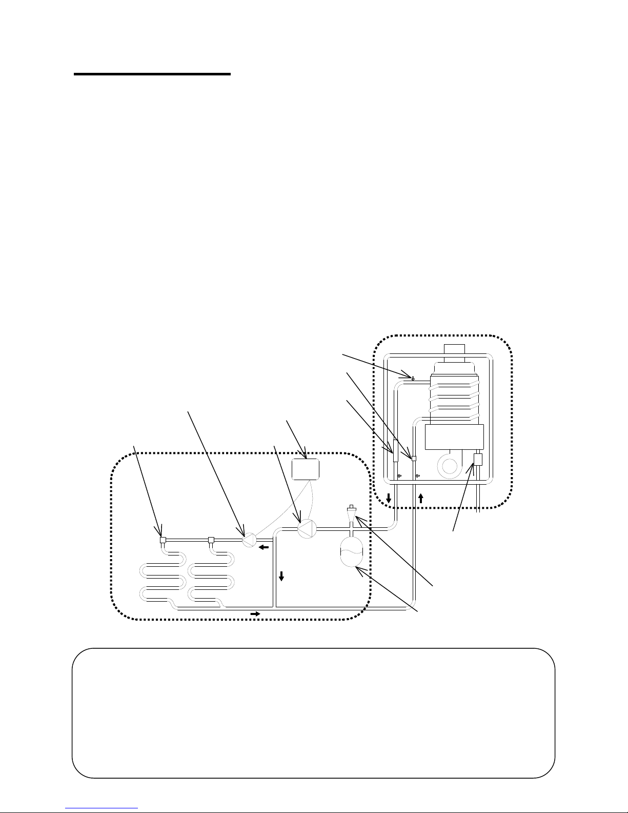
• The principle behind the radiant heating system is simple:
Hydro-Smart 170
Thermistor
Secondary pump
Radiant heating
Heating panel “Integrator”
Water control valve
Pump controller
Primary pump
Flow sensor
Burner
GAS
Gas valve
Air vent
Expansion tank
1. The Primary pump turns on by pump controller.
2. Water enters the heater.
3. The water flow sensor detects the water flow.
4. The computer automatically ignites the burner.
5. Water circulates through the heat exchanger and then gets hot.
6. The computer will modulate the gas supply valve and water flow to produce the right
amount of hot water at the correct temperature.
1. When the Primar
is turned off, the unit shuts down.
3
SAFETY GUIDELINES
• Installation and service must be performed by a qualified installer (for
example, a licensed plumber or gas fitter), otherwise the warranty by Hydro Smart will be void.
• The installer (licensed professional) is responsible for the correct
WARNING
PLEASE READ THIS MANUAL CAREFULLY AND FOLLOW ALL DIRECTIONS.
1. Follow all local codes, or in the absence of local codes, follow the most recent edition of
the National Fuel Gas Code: ANSI Z223.1/NFPA 54 in the USA or CAN/CSA B149.1
Natural Gas, Propane Installation Code in Canada.
2. Properly ground the unit in accordance with all local codes or in the absence of local
codes, with the National Electrical Codes: ANSI/NFPA 70 in the USA or CSA standard
C22.1 Canada Electrical Code Part 1 in Canada.
3. Carefully plan where you intend to install your Hydro-Smart 170. Please ensure:
• Your Hydro-Smart 170 will have enough combustible air and
proper ventilation.
• Locate your Hydro-Smart 170 where water leakage will not
damage surrounding areas (please refer to p. 5).
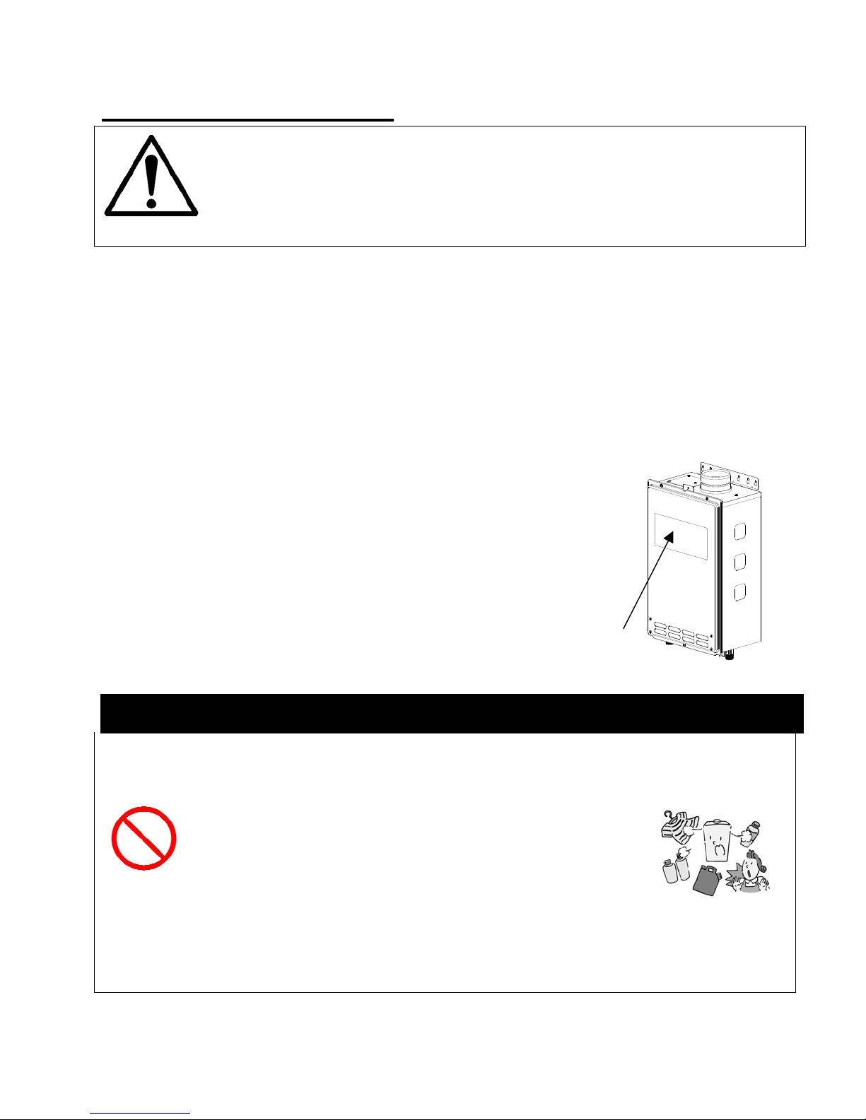
4. Check the rating plate for the correct GAS TYPE, GAS
PRESSURE, WATER PRESSURE and ELECTRIC RATING.
*If this unit does not match your requirements, do not install and
consult with Hydro-Smart.
5. If any problem should occur, turn off all hot water taps and turn off
the gas. Then call a trained technician or the Gas Company or the
manufacturer.
installation of your Hydro-Smart 170 and for compliance with all national,
state/provincial, and local codes.
GENERAL
RATING
PLATE
•
Do not store or use gasoline or other flammables, vapors, or liquids in the vicinity of this
appliance.
• Do not reverse the water and/or gas connections as this will damage the gas valves
and can cause severe injury or death.
• Do not use this appliance if any part has been in contact with or
been immersed in water. Immediately call a licensed plumber, a
Prohibited
licensed gas fitter, or a professional service technician to inspect
and/or service the unit if necessary.
• Do not disconnect the electrical supply if the ambient temperature
will drop below freezing. The Freeze Prevention System only works if the unit has
electrical power. The warranty will not be covered if the heat exchanger is damaged
due to freezing. Refer to the section on the Freeze Prevention System on p. 19 for
more information.
WARNING
4
INSTALLATION
All gas Hydro-Smart 170 require careful and correct installation to ensure safe and efficient
operation. This manual must be followed exactly. Read the “Safety Guidelines” section at the
beginning of this manual.
• The warranty will not cover damage caused by water quality. Water
hardness that leads to scale formation and/or corrosion may affect/damage
the Hydro-Smart 170. Hard water scaling and/or corrosion must be avoided
or controlled by proper water treatment.
CAUTION
WARNING
• Hydro-Smart recommends using the direct vent kit, when the Hydro-
Smart 170 is installed in a beauty salon. Some chemicals used in a
beauty salon may affect the flame sensor. Hydro-Smart 170 may not work
properly.
• Although the Hydro-Smart 170 is designed to operate with minimal sound,
Hydro-Smart does not recommend installing the unit on a wall adjacent
to a bedroom, or a room that is intended for quiet study or meditation,
etc.
• Locate your Hydro-Smart 170 close to a drain where water leakage will not
do damage to surrounding areas. As with any water heating appliance, the
potential for leakage at some time in the life of the product does exist.
Hydro-Smart will not be responsible for any water damage that may occur.
If you install a drain pan under the unit, ensure that it will not restrict the
combustion air flow.
• Hydro-Smart does not recommend installing unit in an attic due to
safety issues.
5
GENERAL
y
1. The manifold gas pressure is preset at the factory. It is computer controlled and should
not need adjustment.
2. Maintain proper space for servicing. Install the unit so that it can be connected or
removed easily. Refer to p. 7 and p. 8 for proper clearances.
3. The electrical connection requires a means of disconnection, to terminate power to the
Hydro-Smart for servicing and safety purposes.
4. If you will be installing the unit in a contaminated area with a high level of dust, sand,
flour, aerosols or other contaminants/chemicals, they can become airborne and enter
and build up within the fan and burner causing damage to the unit. In those
environments (e.g. residential or commercial laundry facilities, hair salons, pet salons,
chemical plants etc.), please purchase the optional TK-TV10 direct vent conversion kit
and convert the Hydro-Smart 170 to a sealed combustion unit. Direct venting allows the
Hydro-Smart 170 to draw fresh intake air from the outside. The warranty will not cover
damage caused to the unit due to installation in a contaminated environment that has
not been converted using the TK-TV10.
5. Particles from flour, aerosols, and other contaminants may clog the air vent or reduce
the functions of the rotating fan and cause improper burning of the gas. Regularly ensure
that the area around the unit is dust- or debris-free; regular maintenance is
recommended for these types of environment.
6. Do not install the unit where the exhaust vent is pointing into any opening in a building or
where the noise may disturb your neighbors. Make sure the vent termination meets the
required distance by local code from any doorway or opening to prevent exhaust from
entering a building (refer to p. 13).
INCLUDED ACCESSORIES
Check that the installation manual and the warranty card are included with the unit.
Items
Manual
Warranty Card
Qty: 1
Qt
: 1
6
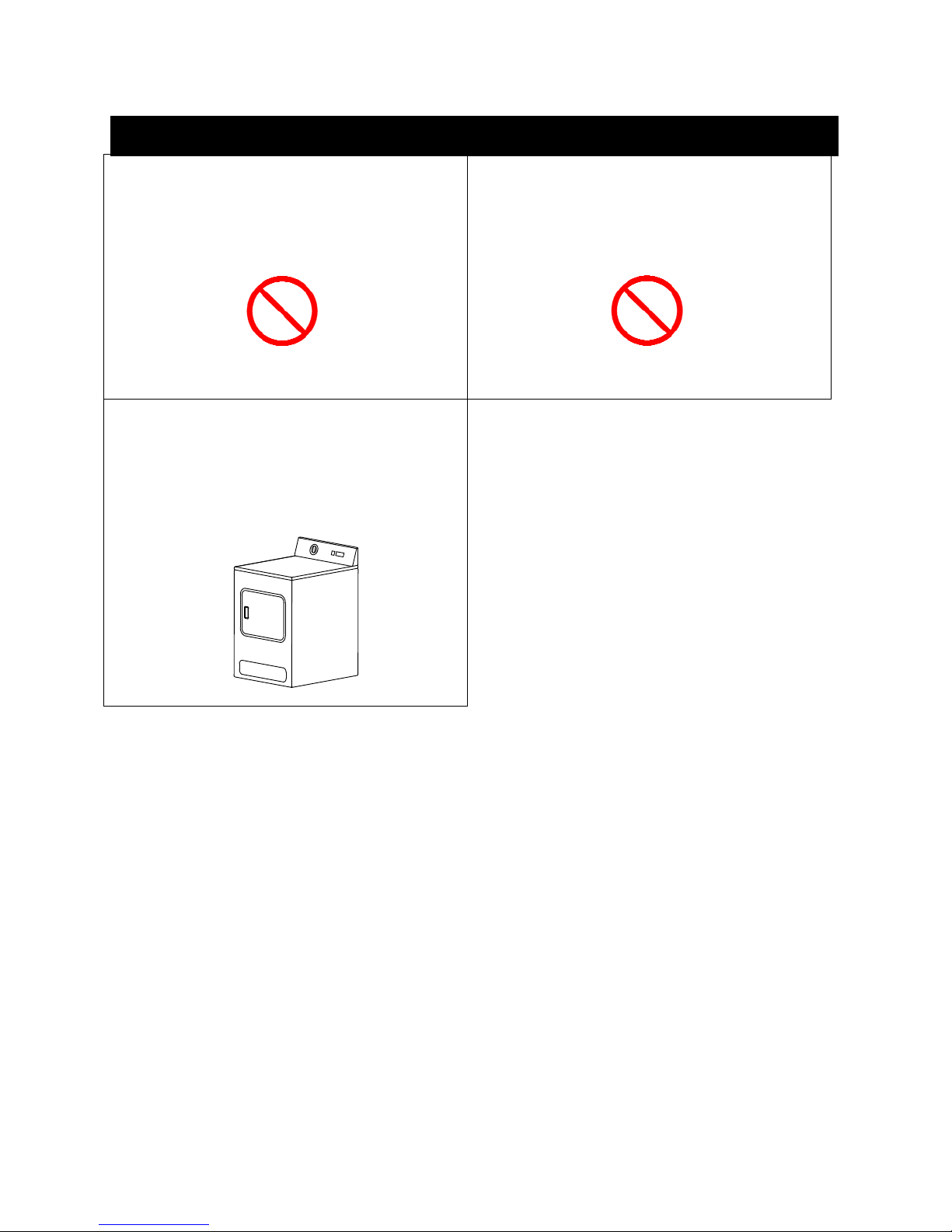
WARNING FOR INSTALLATION LOCATIONS
Do not install the Hydro-Smart 170 where
water, debris or flammable vapors may get
into the flue terminal. This may cause
damage to the Hydro-Smart 170 and void the
warranty.
Prohibited
Do not install next to a dryer or any source of
airborne debris that can be trapped inside the
combustion chamber, unless the system is
direct vented.
Do not have the vent terminal pointing toward
any opening into a building. Do not locate
your Hydro-Smart 170 in a pit or location
where gas and water can accumulate.
Prohibited
7
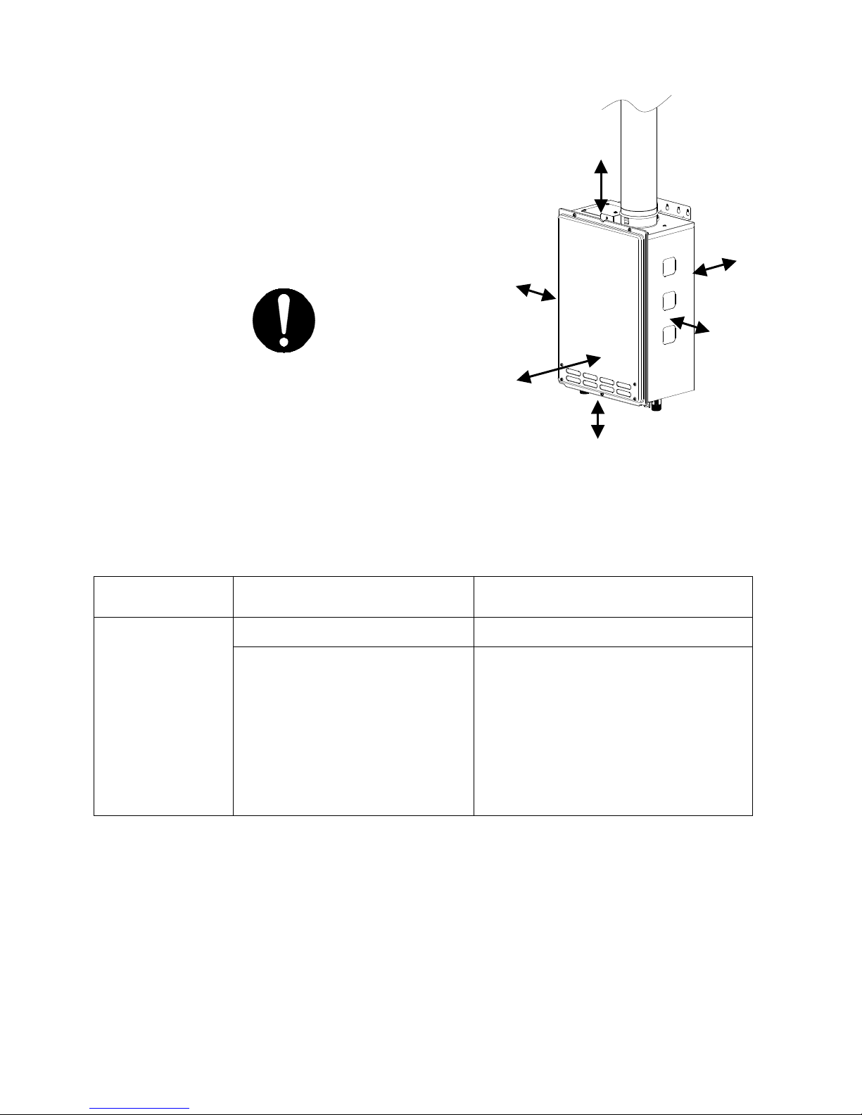
INDOOR INSTALLATION
1. Follow all local codes, or in the absence of local
codes, follow the most recent edition of the National
Fuel Gas Code: ANSI Z223.1/NFPA 54 in the USA
or CAN/CSA B149.1 Natural Gas, Propane
Installation Code in Canada.
2. When installed indoors, the Hydro-Smart 170 shall
be located in an area to maintain the following
minimum clearances around the unit:
Keep the clearances.
Combustion Air Supply
(24” Recommended
for Maintenance)
The Hydro-Smart 170 location must provide enough air for proper combustion and ventilation of
the surrounding area. See the latest edition of ANSI Standard Z223.1 or any applicable local
codes. In general, these requirements specify that if the unit is installed in a confined space,
there must be a permanent air supply opening.
Minimum recommended air supply opening size for Hydro-Smart 170:
Hydro-Smart 170
size
When drawing
make-up air from
outside the building
Side 2”
Front 4”
When drawing make-up
the building (from other rooms within)
Top 12”
Back 1”
Side 2”
Bottom 12”
air from inside
199 Sq. IN
MAX 199,000 BTU
13.3 Sq. IN
When combustion air is supplied
from outside the building, an
opening communicating directly
with the outside should have a
minimum free area of one
square inch per 15,000 BTUH
input of the total input rating of
Hydro-Smart 170 in the
enclosed area.
When combustion air is supplied from
inside the building, an opening
communicating with the rest of the
dwelling should have a minimum free
area of one square inch per 1,000
BTUH input of the total input rating of
Hydro-Smart 170 in the enclosed
area. This opening should never be
less than 199 sq. in.
Combustible Air Supplied by Mechanical fan or Make up air device
The Hydro-Smart 170 is equipped with a combustible air sensor that will shut off the unit when
inadequate combustible air supply to unit is detected.
• If a mechanical fan or make up air device is used to supply air to the Hydro-Smart 170 or
utility room, the installer should make sure it does not create drafts which could cause
nuisance shutdowns.
• If a blower is necessary to provide adequate combustion air to the Hydro-Smart 170, the
blower and Hydro-Smart 170 must be set up so that the Hydro-Smart 170 cannot fire
unless the blower is operating. Possible methods include the use of external flow
sensors/transmitters and relays.
8
DIRECT INTAKE VENT SYSTEM
This Hydro-Smart 170 may be converted to a direct vent (sealed combustion) appliance by
installing an adapter (Part No. TK-TV10) which will bring all required combustible air from
outside the building. When installing the TK-TV10 conversion kit, please follow all instructions
included with the kit.
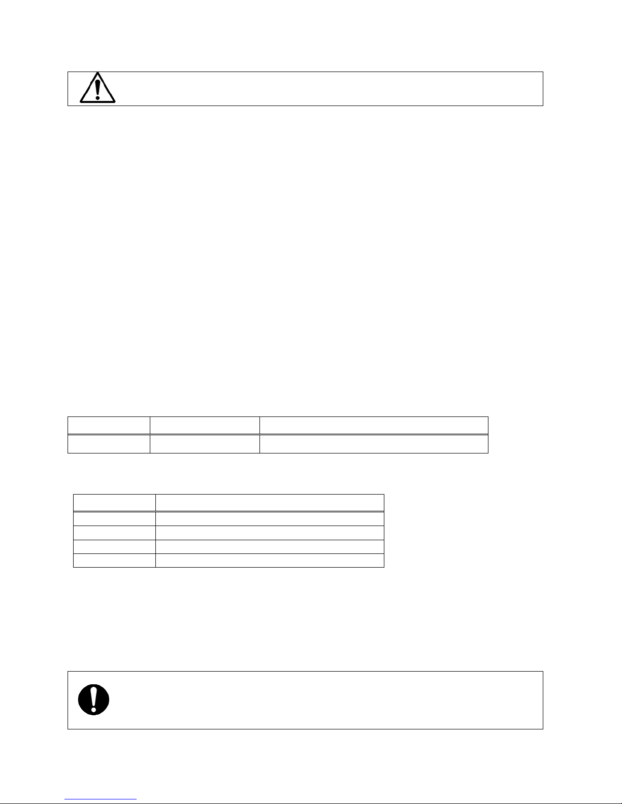
• The Hydro-Smart 170 must be installed in a location where the proper amount of
combustible air will be available to it at all times without obstructions.
• If used as a direct vent appliance, the Hydro-Smart 170 requires a 3” combustible air
supply pipe. The intake pipe must be sealed airtight.
• Air supply pipe can be made of ABS, PVC, galvanized steel, corrugated aluminum,
corrugated stainless steel or Category III stainless steel.
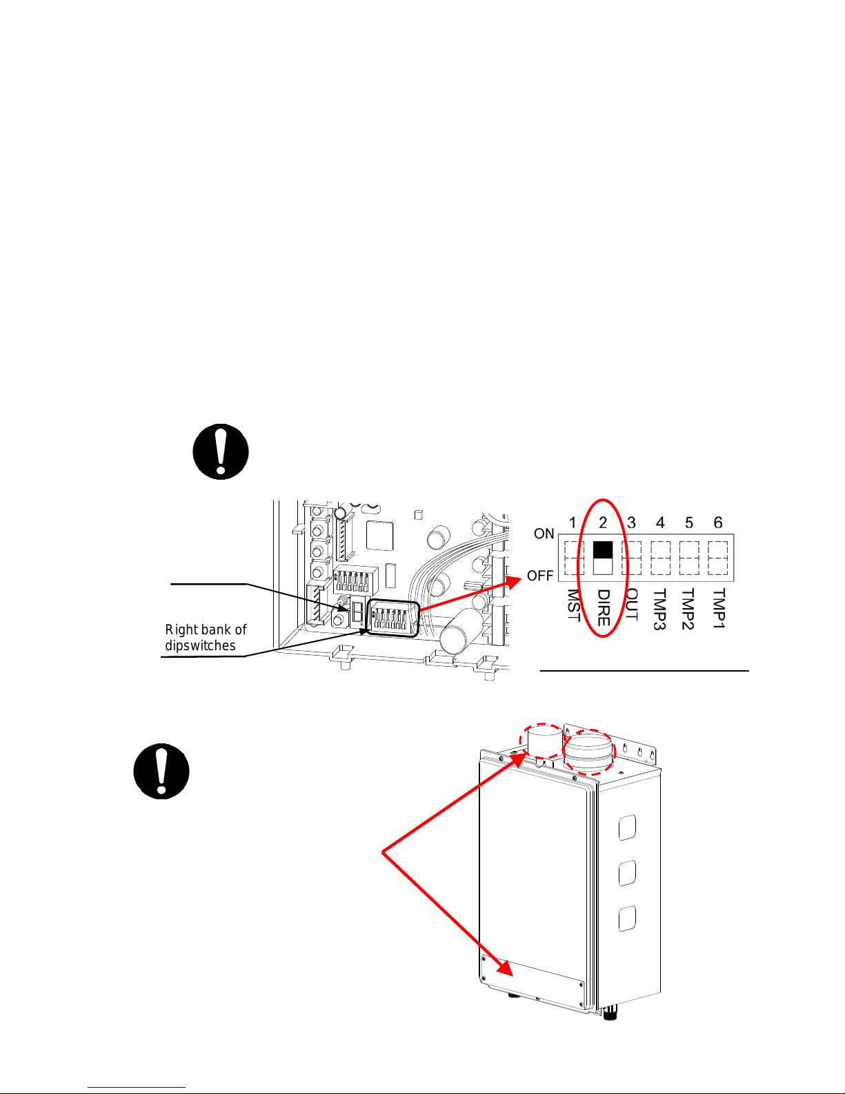
• Change the dipswitch settings to the direct vent system. (See diagram below)
• Sidewall venting is recommended for the direct vent system.
• Hydro-Smart 170 recommends running the exhaust vent and the intake pipe parallel.
7-Seg LED
Make sure power to the unit is
turned OFF before changing
the dipswitch settings.
The dark square is the direction
the dipswitch should be set to.
Right bank of
dipswitches
Right Bank of Dipswitches
INLET
EXHAUST
TK-TV10 Direct Vent
Conversion Kit
TK-TV10
DIRECT VENT
CONVERSION KIT
9
VENTING INSTRUCTIONS
This Hydro-Smart 170 must be vented in accordance with the section “Venting of Equipment" of
the latest edition of the Natural Fuel Gas Code: The ANSI Z223.1, All applicable local building
codes, Section 7 of the CAN/CSA B149.1 Natural Gas in Canada, Propane Installation Code in
Canada.
WARNING: Improper venting of this appliance can result in excessive levels of
carbon monoxide which can result in severe personal injury or death.
EXHAUST VENT
This is a Category III appliance and must be vented accordingly. The vent system must be
sealed air tight. All seams and joints without gaskets must be sealed with high heat resistant
silicone sealant or UL listed aluminum adhesive tape having a minimum temperature rating of
350ºF. For best results, a vent system should be as short and straight as possible.
1. This Hydro-Smart 170 is a Category III appliance and must be vented accordingly with any
4” vent approved for use with Category III or Special BH type gas vent.
2. Hydro-Smart recommends the UL listed venting manufacturer as listed: Takagi
Industrial Co.USA, Inc. (T-Vent), ProTech Systems Inc. (FasNSeal), Flex-L Inc., Z-Flex
Inc. (Z-Vent III), Metal-Fab Inc., and Heat-Fab Inc. (Saf-T Vent).
3. Follow the vent pipe manufacturer’s instructions when installing the vent pipe.
4. Do not common vent this appliance with any other vented appliance (Do not
terminate vent into a chimney. If the vent must go through the chimney, the vent must run
all the way through the chimney with Category III approved or Special BH vent pipe).
5. The maximum length of exhaust vent piping must not exceed 50 ft. deducting 5 ft. for each
elbow used in the venting system. Do not use more than 5 elbows.
Diameter Max. No. of Elbow Max. Vertical or Horizontal run in Length
4” 5 Ea. 50 ft.
*For each elbow added, deduct 5 ft. from max. Vent length.
No. of Elbows Max. Vertical or Horizontal Length
0 50 ft.
1 45 ft.
2 40 ft.
5 25 ft.
6. When the horizontal vent run exceeds 5 ft., support the vent run at 3 ft. intervals with
overhead hangars.
7. Hydro-Smart will not be responsible for any damage to the Hydro-Smart 170 caused by
condensation from the vent. Installing a condensate drip is recommended. Please refer to
p. 12 for the diagrams.
When installing the vent system, all applicable national and local codes must be
followed. If you install thimbles, fire stops or other protective devices and they
penetrate any combustible or noncombustible construction, be sure to follow all
applicable national and local codes.
10
 Loading...