

hydro-s Inverter 6, Inverter 5, Inverter 12, Inverter 9, Inverter 16 User And Service Manual
...
Swimming Pool Heat Pump
7021084
Hydro-S heat pump steel 230V Inverter type 05 horizontal
7021085
Hydro-S heat pump steel 230V Inverter type 06 horizontal
7021086
Hydro-S heat pump steel 230V Inverter type 09 horizontal
7021087
Hydro-S heat pump steel 230V Inverter type 12 horizontal
7021088
Hydro-S heat pump steel 230V Inverter type 16 horizontal
7021089
Hydro-S heat pump steel 230V Inverter type 20 horizontal
User and Service manual
English ● French ● Dutch ● German ● Polish ● Danish


INDEX
CO2 Regulation (EU)
P1~P6
ENGLISH
P7~P36
FRENCH
P37~P62
DUTCH
P63~P90
GERMAN
P91~P120
POLISH
P121~P149
DANISH
P150~P177

1
Regulation (EU) n° 517/2014 of 16/04/14 on fluorinated greenhouse gases and
Load and Tons amounting CO
2
Frequency of test
From 2 at 30 kg load = from 5 at 50 Tons
Each year
repealing Regulation (EC) n° 842/2006
Leak checks
1. Operators of equipment that contains fluorinated greenhouses gases in quantities of 5 tons of CO2, equivalent or
more and not contained in foams shall ensure that the equipment is checked for leaks.
2. For equipment that contains fluorinated greenhouse gases in quantities of 5 tons of CO2equivalent or more, but
of less than 50 tons of CO2equivalent: at least every 12 months.
Picture of the equivalence CO
2
1. Load in kg and Tons amounting CO2.
Concerning the Gaz R 410a, 2.39kg amounting at 5 tons of CO2, commitment to check each year.
Training and certification
1. The operator of the relevant application shall ensure that the relevant personnel have obtained the necessary
certification, which implies appropriate knowledge of the applicable regulations and standards as well as the
necessary competence in emission prevention and recovery of fluorinated greenhouse gases and handling safety
the relevant type and size of equipment.
Record keeping
1. Operators of equipment which is required to be checked for leaks, shall establish and maintain records for each
piece of such equipment specifying the following information:
a) The quantity and type of fluorinated greenhouse gases installed;
b) The quantities of fluorinated greenhouse gases added during installation, maintenance or servicing or due to
leakage;
c) Whether the quantities of installed fluorinated greenhouse gases have been recycled or reclaimed, including the
name and address of the recycling or reclamation facility and, where applicable, the certificate number;
d) The quantity of fluorinated greenhouse gases recovered
e) The identity of the undertaking which installed, serviced, maintained and where applicable repaired or
decommissioned the equipment, including, where applicable, the number of its certificate;
f) The dates and results of the checks carried out;
g) If the equipment was decommissioned, the measures taken to recover and dispose of the fluorinated
greenhouse gases.
2. The operator shall keep the records for at least five years, undertakings carrying out the activities for operators
shall keep copies of the records for at least five years.

2
Règlement (UE) n° 517/2014 du 16/04/14 relatif aux gaz à effet de serre fluorés et
Charge et Tonnes équivalant CO2
Fréquence du contrôle
De 2 à 30 kg de charge soit de 5 à 50 Tonnes
Tous les ans
abrogeant le règlement (CE) n° 842/2006
Contrôles d’étanchéité
1. Les exploitants d’équipements qui contiennent des gaz à effet de serre fluorés dans des quantités supérieures ou
égales à 5 tonnes équivalent CO2, veillent à ce que ces équipements fassent l’objet de contrôles d’étanchéité.
2. Au 1 janvier 2017 les contrôles d’étanchéité sont à effectuer au moins tous les douze mois, pour les équipements
dans des quantités supérieures ou égales à 5 tonnes équivalent CO2mais inférieures à 50 tonnes équivalent CO
2.
Tableau des équivalences CO
2
1. Charge en kg et Tonnes équivalant CO2.
Pour le Gaz R 410a, 2.39kg équivalences à 5 tonnes de CO2 donc devoir de vérifier tous les ans.
Formation et certification
1. L'exploitant veille à ce que le personnel concerné ait obtenu la certification nécessaire, qui implique une
connaissance appropriée des règlements et des normes applicables ainsi que la compétence nécessaire en termes
de prévention d'émission, de récupération des gaz à effet de serre fluorés, de manipulation sans danger pour les
contrôles d’étanchéité de l’équipement.
Tenue de registres
1. Les exploitants d’équipements qui doivent faire l’objet d’un contrôle d’étanchéité établissent et tiennent à jour,
pour chaque pièce de ces équipements, des registres dans lesquels ils consignent les informations suivantes :
a) La quantité et le type de gaz à effet de serre fluorés installées;
b) Les quantités de gaz ajoutées pendant l’installation, la maintenance ou l’entretien ou à cause d’une fuite;
c) La quantité de gaz installés qui a été éventuellement recyclée ou régénérée, y compris le nom et l’adresse de
l’installation de recyclage ou de régénération et, le cas échéant, le numéro de certificat;
d) La quantité de gaz récupérée;
e) L’identité de l’entreprise qui a assuré l’installation, l’entretien, la maintenance et, le cas échéant, la réparation ou
la mise hors service de l’équipement, y compris, le cas échéant, le numéro de son certificat;
f) Les dates et les résultats des contrôles effectués;
g) Si l’équipement a été mis hors service, les mesures prises pour récupérer et éliminer les gaz.
2. Les exploitants conservent les registres visés audit paragraphe pendant au moins cinq ans, les entreprises
exécutant les activités pour le compte des exploitants conservent des copies des registres visés au paragraphe 1
pendant au moins cinq ans.

3
Verordening (EU) nr. 517/2014 van het Europees Parlement en de Raad van 16 april
Lading en Ton van hoeveelheid CO
2
Testfrequentie
Van 2 tot 30 kg lading = van 5 tot 50 Ton
Ieder jaar
2014 betreffende gefluoreerde broeikasgassen en tot intrekking van Verordening (EC)
nr. 842/2006
Controle op lekkages
1. Exploitanten van apparatuur die gefluoreerde broeikasgassen in hoeveelheden van 5 ton CO2, zelfde aantal of meer bevatten en niet
verpakt in het isolatieschuim dragen er zorg voor dat de apparatuur wordt gecontroleerd op lekken.
2. Voor apparatuur die gefluoreerde broeikasgassen in hoeveelheden van 5 ton CO2 zelfde aantal of meer bevatten, maar minder dan
50 ton CO2-equivalent: tenminste iedere 12 maanden.
Beeld van de CO
1. Lading in kg en Ton van hoeveelheid CO2.
equivalent
2-
Met betrekking tot Gaz R 410a, 2.39kg met de hoeveelheid 5 ton CO2, toewijding aan jaarlijkese controle.
Training en certificatie
1. De exploitant van de betreffende toepassing zal er voor zorg dragen dat het betrokken personeel de nodige certificering hebben
verkregen, hetgeen inhoudt voldoende kennis van de geldende voorschriften en norm te bezitten, alsmede de nodige deskundigheid in
emissiepreventie en terugwinning van gefluoreerde broeikasgassen en hanteren van de veiligheid van de betreffende type en de
omvang van de apparatuur.
Registratie
1. Exploitanten van apparatuur die verplicht zijn op lekkage te controleren, zullen registers aanmaken en bijhouden voor elk deel van
dergelijke apparatuur dat de volgende informatie bevat:
a) De hoeveelheid en het type van de geïnstalleerde gefluoreerde broeikasgassen;
b) De hoeveelheden gefluoreerde broeikasgassen toegevoegd tijdens het installeren, onderhoud of de service of als gevolg van lekkage;
c) Of de hoeveelheden van de geïnstalleerde gefluoreerde broeikasgassen zijn gerecycleerd of teruggewonnen, inclusief de naam en
het adres van de recycling- of terugwinningsinstallatie en waar van toepassing het certificaatnummer;
d) De hoeveelheid teruggewonnen gefluoreerde broeikasgassen
e) De identiteit van de onderneming die de installatie, reparatie, onderhoud uitvoert en voor zover van toepassing raparties of
verwijdering van apparatuur voor zijn rekening neemt, inclusief, in voorkomend geval, het nummer van haar certificaat;
f) De data en de resultaten van de verrichte controles;
g) Indien de apparatuur buitengebruik werd gesteld, de genomen maatregelen voor het terugwinnen en afvoeren van de gefluoreerde
broeikasgassen.
2. De exploitant zal de administratie gedurende tenminste vijf jaar bewaren, de ondernemingen die de werkzaamheden voor de
exploitanten uitvoeren, moeten tenminste vijf jaar kopieën van de registers bijhouden.

4
Verordnung (EU) Nr. 517/2014 vom 16/04/14 über fluorierte Treibhausgase und die
Belastung und Tonnen von CO2
Häufigkeit der Prüfung
Von 2 bei 30 kg Belastung = von 5 bei 50 Tonnen
Jedes Jahr
1. Die Betreiber der betreffenden Anwendung sollen dafür Sorge tragen, dass die zuständige Person die erforderliche Zertifizierung
erlangt hat, die die angemessene Kenntnisse der geltenden Vorschriften und Normen sowie die notwendige Kompetenz in Bezug auf
die Emissionsvermeidung und - verwertung von fluorierten Treibhausgasen und der Handhabungssicherheit der betreffenden Typen
und Größe der Ausrüstung beinhaltet.
Aufbewahrung der Aufzeichnungen
1. Die Betreiber von den Geräte, die auf Dichtheit überprüft werden müssen, müssen für jedes Gerät, das die folgenden Angaben
enthält, Aufzeichnungen erstellen und verwalten:
a) Die Menge und Art der installierten fluorierten Treibhausgase;
b) Die Mengen an fluorierten Treibhausgasen, die während der Installation, Wartung oder Service oder aufgrund von Leckagen
hinzugefügt werden;
c) Ob die Mengen der installierten fluorierten Treibhausgase wiederverwandt oder zurückgefordert wurden, einschließlich der Name
und Anschrift der Wiederverwendung oder Rückgewinnungsanlage und gegebenenfalls der Bescheinigungsnummer;
d) Die Menge der fluorierten Treibhausgase wiederhergestellt wird;
e) Die Identität des Unternehmens, das die Ausrüstung installiert, gewartet und gegebenenfalls repariert oder außer Betrieb hat,
gegebenenfalls einschließlich der Nummer des Zertifikats;
f) Datum und Ergebnisse der Prüfung durchgeführt werden;
g) Wenn das Gerät außer Betrieb hat, wurden die Maßnahmen zur Rückgewinnung und Beseitigung der fluorierten Treibhausgase
getroffen.
2. Die Betreiber bewahrendie Aufzeichnungen für mindestens fünf Jahre lang auf, wobei die Unternehmen, die die Tätigkeiten für
die Betreiber ausführen, die Aufzeichnungen für mindestens fünf Jahre lang aufbewahren soll.
Verordnung (EG) zur Aufhebung Nr. 842/2006
Dichtheitsprüfung
1. Die Betreiber von den Geräte, die die fluorierte Treibhausgase in Mengen von 5 Tonnen CO2-Äquivalent oder mehr enthalten und
nicht in Schäumen enthalten, müssen sicherstellen, dass das Gerät auf Dichtheit überprüft wird.
2. Für die Geräte, die fluorierte Treibhausgase in Mengen von 5 Tonnen 5 Tonnen CO2-Äquivalent oder mehr enthalten aber weniger als
50 Tonnen CO2-Äquivalent enthalten: mindestens alle 12 Monate.
Bild der Gleichwertigkeit CO
1. Belastung von CO2 in kg und Tonnen.
2
In Bezug auf die Gaz R410a, 2,39 kg in Höhe von 5 Tonnen CO2, Engagement für die Überprüfung jedes Jahr.
Ausbildung und Zertifizierung

5
Regulacje (EU) n°517/2014 z 16/04/14 na temat fluorowanego gazu cieplarnianego i
Ilość i tony CO
2
Częstotliwość testu
Od 2 na 30 kg = od 5 na 50 ton
Co roku
unieważnienie (EC) n° 842/2006
Kontrole szczelności
1. Operator sprzętu który zawiera 5 ton CO2fluorowanego gazu cieplarnianego, odpowiednik lub większa ilość oraz brak pianki
powoduje sprawdzenie sprzętu pod kątem szczelności.
2. Dla sprzętu zawierającego fluorowany gaz cieplarniany w ilości 5 ton CO2,lub więcej, ale mniej niż 50 ton CO2jest sprawdzany co 12
miesięcy.
Obrazek CO
1. Ilość CO2w kg i tonach.
2
Gas R 410a, 2.39kg jest równowartością 5 ton CO2i jest sprawdzany każdego roku.
Trening I certyfikacja
1. Personel musi posiadać odpowiednią certyfikację, która zapewnia odpowiednią wiedzę na temat standardów oraz odpowiednie
kompetencje w zakresie prewencji emisji i odyzskania fluorowanego gazu cieplarnianego jak i musi zachować wszelkie normy
bezpieczeństwa oraz odpowiedniego sprzętu.
Prowadzenie dokumentacji
1. Operatorzy sprzętu, którego jest wymagana kontrola pod względem szczelności, muszą prowadzić dokumentację dla całego sprzętu
tj:
a) IIość i typ zainstalowanego fluorowanego gazu cieplarnianego.
b) Ilości fluorowanego gazu cieplarnianego dodanego podczas instalacji - prowadzenie i serwis.
c) Czy ilośći zainstalowanego fluorowanego gazu cieplarnianego zostały przetworzone lub odzyskane, z załączeniem nazwy i adresu
miejsca przetworzenia lub reklamacji oraz jeśli możliwy - numer certyfikatu.
d) Ilość odzyskanego fluorowanego gazu cieplarnianego.
e) Dane firmy instalującej, serwisującej, konserwującej i jeśli możliwa naprawa lub likwidacja sprzętu oraz jego numer cerrtyfikatu.
f) Daty i rezultaty przeprowadzonych testów.
g) Jeśli sprzęt został zlikwidowany – wymagane środki do odzyskania i rozłożenia fluorowanego gazu cieplarnianego.
2. Operator musi zachować rejestry przez minimum pięć lat, firmy przeprowadzające zlecenia operatorów muszą zatrzymać kopie
rejestrów przez minimum pięć lat.

6
Förordning (EU) Nr: 517/2014 den 16/04/14 om fluorerade växthusgaser och
Belastning i kg och ton uppgående CO
2
.
Testfrekvens
Från 2 till 30 kg belastning = från 5 till 50 ton
Varje år
upphävande av förordning (EC) Nr: 842/2006
Läckagekontroll
1. Operatörer av utrustning som innehåller fluorerade växthusgaser i mängder på 5 ton CO2-ekvivalenter eller mer och inte ingår i skum
ska se till att utrustningen kontrolleras för läckor.
2. För utrustning som innehåller fluorerade växthusgaser i mängder på 5 ton CO2-ekvivalenter eller mer, men mindre än 50 ton
CO2-ekvivalenter: åtminstone var 12 månad.
Bild på likvärdig CO
1. Belastning i kg och ton uppgående CO2.
2
När det gäller Gaz R 410a, 2,39 kg uppgående till 5 ton CO2, åtagande att kontrollera varje år.
Utbildning och certifiering
1. Operatören av den aktuella ansökan skall se till att berörd personal har erhållit den nödvändiga certifieringen, vilket innebär
tillräcklig kunskap om gällande föreskrifter och standarder samt nödvändig kompetens i förebyggande av utsläpp och återvinning av
fluorerade växthusgaser och hantering med säkerhet utrustning av relevant typ och storlek.
Journalföring
1. Operatörer av utrustning som kräver kontroll av läckage, ska upprätta och föra register för varje del av sådan utrustning och
specificera följande information:
a) Mängd och typ av installerade fluorerade växthusgaser;
b) Mängd fluorerade växthusgaser som tillkommit under installation, underhåll eller service eller på grund av läckage;
c) Om kvantiteter av installerade fluorerade växthusgaser har återanvänts eller regenerats, inklusive namn och adress på
återanvändnings- eller regenereringsanläggning och, i förekommande fall, certifieringsnummer;
d) Mängd fluorerade växthusgaser som har återvunnits
e) Identitet på företag som installerat, utfört service, underhållit och i förekommande fall reparerat eller demonterat utrustning,
inklusive, i förekommande fall, dess certifieringsnummer;
f) Datum och resultat av de kontroller som utförts;
g) Om utrustningen tagits ur drift, de åtgärder som vidtagits för att återvinna och göra sig av med de fluorerade växthusgaserna.
2. Operatören skall föra register under minst fem år, företag som bedriver verksamhet för operatörerna ska bevara kopior av dessa
uppgifter under minst fem år.

7
Swimming Pool Heat Pump
1. Specifications
2. Dimension
3. Installation and connection
4. Accessories
5. Electrical Wiring
6. Display Controller Operation
7. Troubleshooting
8. Exploded Diagram
9. Maintenance
10. Warranty and returns
ATTENTION: This manual includes all the necessary information with the use and the installation of your
heat pump.
The installer must read the manual and attentively follow the instructions in implementation and maintenance.
The installer is responsible for the installation of the product and should follow all the instructions of the
manufacturer and the regulations in application. Incorrect installation against the manual implies the exclusion of
the entire guarantee.
The manufacturer declines any responsibility for the damage caused with the people, objects and of the errors due
to the installation that disobey the manual guideline. Any use that is without conformity at the origin of its
manufacturing will be regarded as dangerous.
User and Service manual
INDEX
Thank you for using hydro-s inverter swimming pool heat pump for your pool heating, it will heat your pool water
and keep the constant temperature when the air ambient temperature is at -12 to 50℃
WARNING: Please always empty the water in heat pump during winter time or when the ambient temperature
drops below 0℃, or else the Titanium exchanger will be damaged because of being frozen, in such case, your
warranty will be lost.
WARNING: Please always cut the power supply if you want to open the cabinet to reach inside the heat pump,
because there is high voltage electricity inside.
WARNING: Please well keep the display controller in a dry area, or well close the insulation cover to protect the
display controller from being damaged by humidity.
8
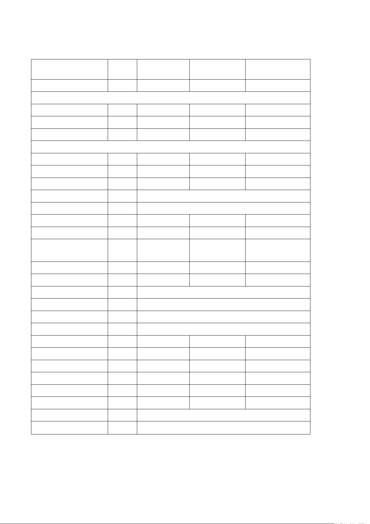
1. Specifications
1.1 Technical data hydro-s inverter pool heat pumps
Model
Hydro-S Inverter 5
Hydro-S Inverter 6
Hydro-S Inverter 9
Item No.
7021084
7021085
7021086
* Performance at Air 27℃, Water 26℃, Humidity 80%
Heating capacity
kW
4.9-3.2
5.5-3.3
8-3.5
Power consumption
kW
0.96 -0.43
1.04-0.43
1.42-0.43
C.O.P.
7.4-5.1
7.7-5.3
8-5.6
* Performance at Air 15℃, Water 26℃, Humidity 70%
Heating capacity
kW
4-2.3
4.5-2.4
6.2-2.5
Power consumption
kW
0.89-0.43
1-0.43
1.4-0.43
C.O.P.
5.4-4.5
5.6-4.5
5.8-4.4
Compressor type
GMCC/ TOSHIBA
Voltage
V
220~240V/50Hz/1PH
Rated current
A
4.2
4.8
6.1
Minimum fuseA7710
Advised pool volume
(with pool cover)
m³
0-15
10—25
15—30
Advised water flux
m3/h
2.50
2.50
2.80
Water pressure drop
Kpa1212
12
Heat exchanger
Twist-titanium tube in PVC
Water connection
mm
50
Fan quantity
1
Ventilation type
Horizontal
Fan speed
RPM
750-870
750-870
750-870
Power input of Fan
W8080
80
Noise level(10m)
dB(A)
47-41
47-42
47-42
Noise level(1m)
dB(A)
50-47
50-48
50-48
Net Weightkg465160
Gross Weightkg495463
Net Dimension
mm
935*360*545
Packing Dimension
mm
1060*380*595
* Above data are subjects to modification without notice.

9
1.2 Technical data hydro-s inverter pool heat pumps
Model
Hydro-S Inverter 12
Hydro-S Inverter 16
Hydro-S Inverter 20
Item No.
7021087
7021088
7021089
* Performance at Air 27℃, Water 26℃, Humidity 80%
Heating capacity
kW
12-4.8
15-5.3
19-4.7
Power consumption
kW
2.14-0.6
2.7-0.66
3.7-0.57
C.O.P.
8-5.6
8-5.5
8.2-5.1
* Performance at Air 15℃, Water 26℃, Humidity 70%
Heating capacity
kW
8.2-3.5
11.5-3.8
14.6-3.4
Power consumption
kW
1.86-0.6
2.73-0.66
3.65-0.57
C.O.P.
5.8-4.4
5.8-4.2
5.8-4
Compressor type
GMCC/ TOSHIBA
MITSUBISHI
Voltage
V
220~240V/50Hz/1PH
Rated currentA8.2
11.9
16.4
Minimum fuseA131624
Advised pool volume
(with pool cover)
m³
20—60
30-100
55-120
Advised water flux
m3/h
3.70
4.90
5.0
Water pressure drop
Kpa1415
18
Heat exchanger
Twist-titanium tube in PVC
Water connection
mm
50
Fan quantity
1
Ventilation type
Horizontal
Fan speed
RPM
550-650
550-650
450-650
Power input of Fan
W
200
200
200
Noise level(10m)
dB(A)
50-46
50-46
50-46
Noise level(1m)
dB(A)
54-50
54-50
54-50
Net Weightkg758098
Gross Weightkg8085113
Net Dimensionmm1065*425*703
1103*420*855
Packing Dimensionmm1135*445*843
1160*440*995
* Above data are subjects to modification without notice.
10
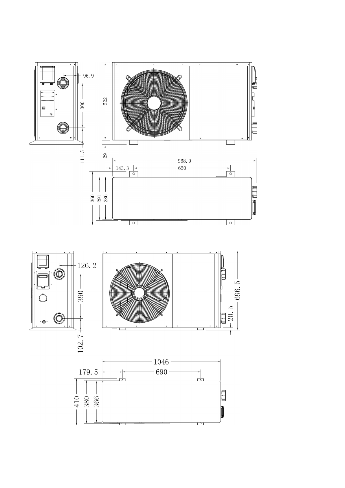
2. Dimension (mm)
Hydro-S Inverter 5/6/9
Hydro-S Inverter 12/16
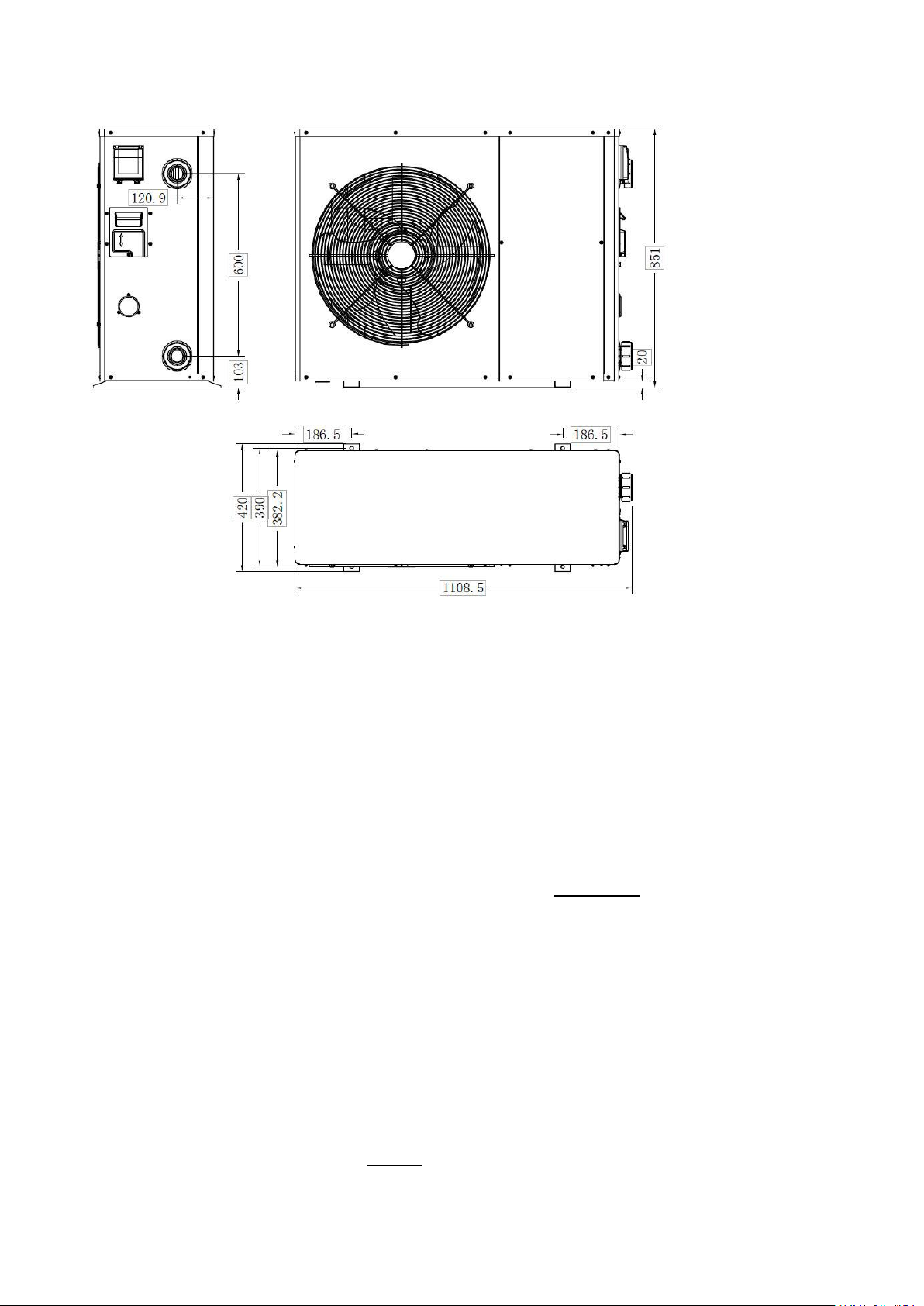
11
Hydro-S Inverter 20
3. Installation and connection
The factory supplies only the heat pump. All other components, including a bypass if necessary, must be provided
by the user or the installer.
Attention:
Please observe the following rules when installing the heat pump:
1. Any addition of chemicals must take place in the piping located downstream from the heat pump.
2. Install a bypass if the water flow from the swimming pool pump is more than 20% greater than the
allowable flow through the heat exchanger of the heat pump.
3. Always place the heat pump on a solid foundation and use the included rubber mounts to avoid vibration
and noise.
4. Always hold the heat pump upright. If the unit has been held at an angle, wait at least 24 hours before
starting the heat pump.
The unit will work properly in any desired location as long as the following three items are present:
1. Fresh air – 2. Electricity – 3. Swimming pool filters
The unit may be installed in virtually any outdoor location as long as the specified minimum distances to other
objects are maintained (see drawing below). Please consult your installer for installation with an indoor pool.
Installation in a windy location does not present any problem at all, unlike the situation with a gas heater (including
3.1 Notes
3.2 Heat pump location
12
pilot flame problems).
ATTENTION: Never install the unit in a closed room with a limited air volume in which the air expelled from the unit
will be reused, or close to shrubbery that could block the air inlet. Such locations impair the continuous supply of
fresh air, resulting in reduced efficiency and possibly preventing sufficient heat output.
See the drawing below for minimum dimensions.
3.3 Distance from your swimming pool
The heat pump is normally installed within a perimeter area extending 7.5 m from the swimming pool. The greater
the distance from the pool, the greater the heat loss in the pipes. As the pipes are mostly underground, the heat
loss is low for distances up to 30 m (15 m from and to the pump; 30 m in total) unless the ground is wet or the
groundwater level is high. A rough estimate of the heat loss per 30 m is 0.6 kWh (2,000 BTU) for every 5 ºC
difference between the water temperature in the pool and the temperature of the soil surrounding the pipe. This
increases the operating time by 3% to 5%.
3.4 Check-valve installation
Note: If automatic dosing equipment for chlorine and acidity (pH) is used, it is essential to protect the heat pump
against excessively high chemical concentrations which may corrode the heat exchanger. For this reason, equipment
of this sort must always be fitted in the piping on the downstream side of the heat pump, and it is recommended to
install a check-valve to prevent reverse flow in the absence of water circulation.
Damage to the heat pump caused by failure to observe this instruction is not covered by the warranty.
13
3.5 Typical arrangement
Out In
Heat Pump
Use the following procedure to adjust
the bypass:
1.Valve 1 wide open. Valve 2 &
valve 3 closed.
2.Slowly open valve 2 & valve 3 by
half, then close the valve 1 slowly
to increase the water flow to valve 2
& valve 3.
3. If it shows ‘ON’ or ‘EE3’ on
display, it means the water flow into
heat pump is not enough, then you
need adjust the valves to increase
the water flow through the heat
pump.
To pool
From pool
Note: This arrangement is only an illustrative example.
3.6 Adjusting the bypass
How to get the optimum water flow:
Please turn on the heat pump under heating function, firstly close the by-pass then open it slowly to start the heat
pump (the machine can't start running when the water flow is insufficient).
Continue to adjust the by-pass, at the meantime to check the Inlet water temp. & Outlet water temp., it will be

14
optimum when the difference is around 2 degree.
3.7 Electrical connection
Note: Although the heat pump is electrically isolated from the rest of the swimming pool system, this only
prevents the flow of electrical current to or from the water in the pool. Earthing is still required for protection
against short-circuits inside the unit. Always provide a good earth connection.
Before connecting the unit, verify that the supply voltage matches the operating voltage of the heat pump.
It is recommended to connect the heat pump to a circuit with its own fuse or circuit breaker (slow type; curve D)
and to use adequate wiring.
Connect the electrical wires to the terminal block marked ‘ POWER SUPPLY ’.
A second terminal block marked ‘WATER PUMP ’ is located next to the first one. The filter pump (max. 5 A / 240 V)
can be connected to the second terminal block here. This allows the filter pump operation to be controlled by the
heat pump.
1. Switch on the filter pump. Check for leaks and verify that water is flowing from and to the swimming pool.
2. Connect power to the heat pump and press the On/Off button on the electronic control panel. The unit will
3. After a few minutes, check whether the air blowing out of the unit is cooler.
4. When turn off the filter pump , the unit should also turn off automatically , if not, then adjust the flow switch.
3.9 Condensation
Note: In the case of three-phase models, swapping two phases may cause the electric motors to run in the reverse
direction, which can lead to damage. For this reason, the unit has a built-in protective device that breaks the circuit
if the connection is not correct. If the red LED above this safety device lights up, you must swap the connections of
two of the phase wires.
3.8 Initial operation
Note: In order to heat the water in the pool (or hot tub), the filter pump must be running to cause the water to
circulate through the heat pump. The heat pump will not start up if the water is not circulating.
After all connections have been made and checked, carry out the following procedure:
start up after the time delay expires .
Depending on the initial temperature of the water in the swimming pool and the air temperature, it may take
several days to heat the water to the desired temperature. A good swimming pool cover can dramatically reduce
the required length of time.
Water Flow Switch:
It is equipped with a flow switch for protecting the HP unit running with adequate water flow rate .It will turn on wh
en the pool pump runs and shut it off when the pump shuts off. If the pool water level higher than 1 m above or b
elow the heat pump’s automatic adjustment knob, your dealer may need to adjust its initial startup.
Time delay - The heat pump has a built-in 3-minute start-up delay to protect the circuitry and avoid excessive
contact wear. The unit will restart automatically after this time delay expires. Even a brief power interruption will
trigger this time delay and prevent the unit from restarting immediately. Additional power interruptions during this
delay period do not affect the 3-minute duration of the delay.
The air drawn into the heat pump is strongly cooled by the operation of the heat pump for heating the pool water,
which may cause condensation on the fins of the evaporator. The amount of condensation may be as much as
several litres per hour at high relative humidity. This is sometimes mistakenly regarded as a water leak.
15
3.10 Operating modes for optimal use
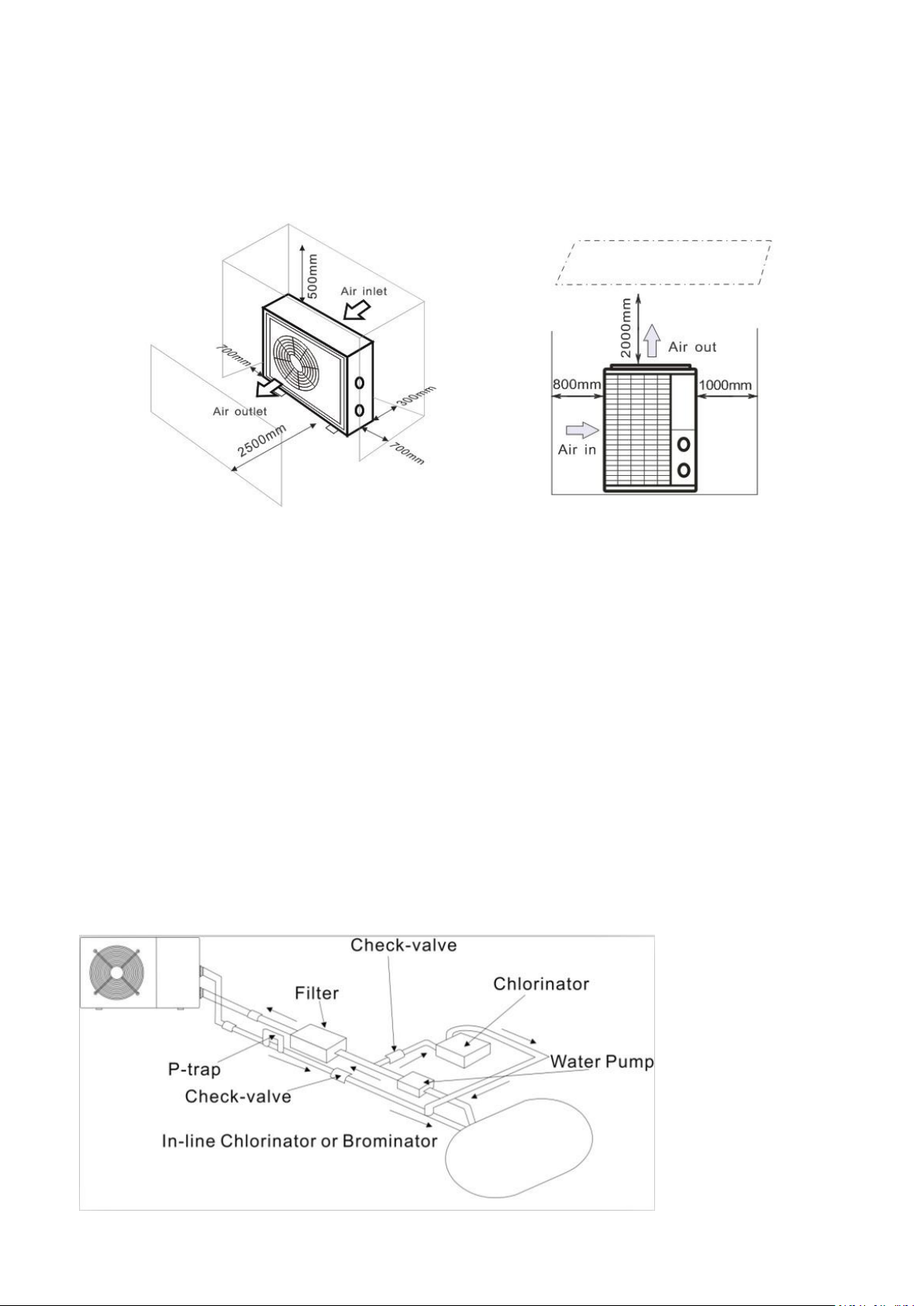
Anti-vibration base, 4 pcs
Draining jet, 2 pcs
Waterproof box, 1 pc
10M Signal wire, 1 pc
Water drainage pipes, 2 pcs
- POWER: Used primarily at the beginning of the season because this mode allows very rapid temperature rise
- SMART: The heat pump has completed its primary task, in this mode; the heat pump is in a position to maintain
the pool water in an energy efficient manner. By automatically adjusting speed of compressor and fan the heat
pump delivers a better return.
- SILENT: In the summer months when the heat output is minimal required, the heat pump in this mode is even
more profitable. Added benefit; when the heat pump heats. It goes with minimal noise load.
4. Accessories
4.1 Accessories list
16
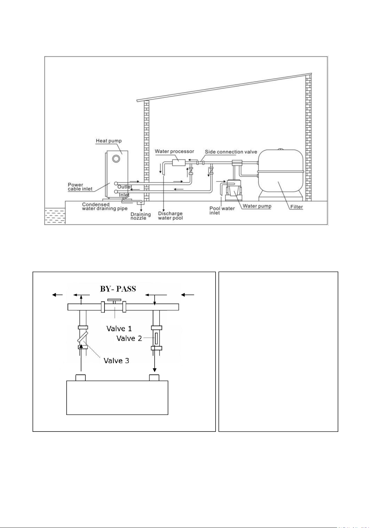
4.2 Accessories Installation
Anti-vibration bases
1. Take out 4 Anti-vibration bases
2. Put them one by one on the bottom of
machine like the picture.
Draining jet
1. Install the draining jet under the
bottom panel
2. Connect with a water pipe to drain out
the water.
Note: Lift the heat pump to install the jet.
Never overturn the heat pump, it could
damage the compressor.
Water Inlet & outlet junction
1. Use the pipe tape to connect the water
Inlet & outlet junction onto the heat
pump
2. Install the two joints like the picture
shows
3. Screw them onto the water Inlet &
outlet junction
Cable wiring
1. Connect the power supply wire
through the white hole like the picture
shows.
2. Fix the other side on joints inside the
electric box.
17
Water pump wiring
1. Connect the water pump wire through
the white hole marked
2. Fix the other side on joints inside the
electric box.
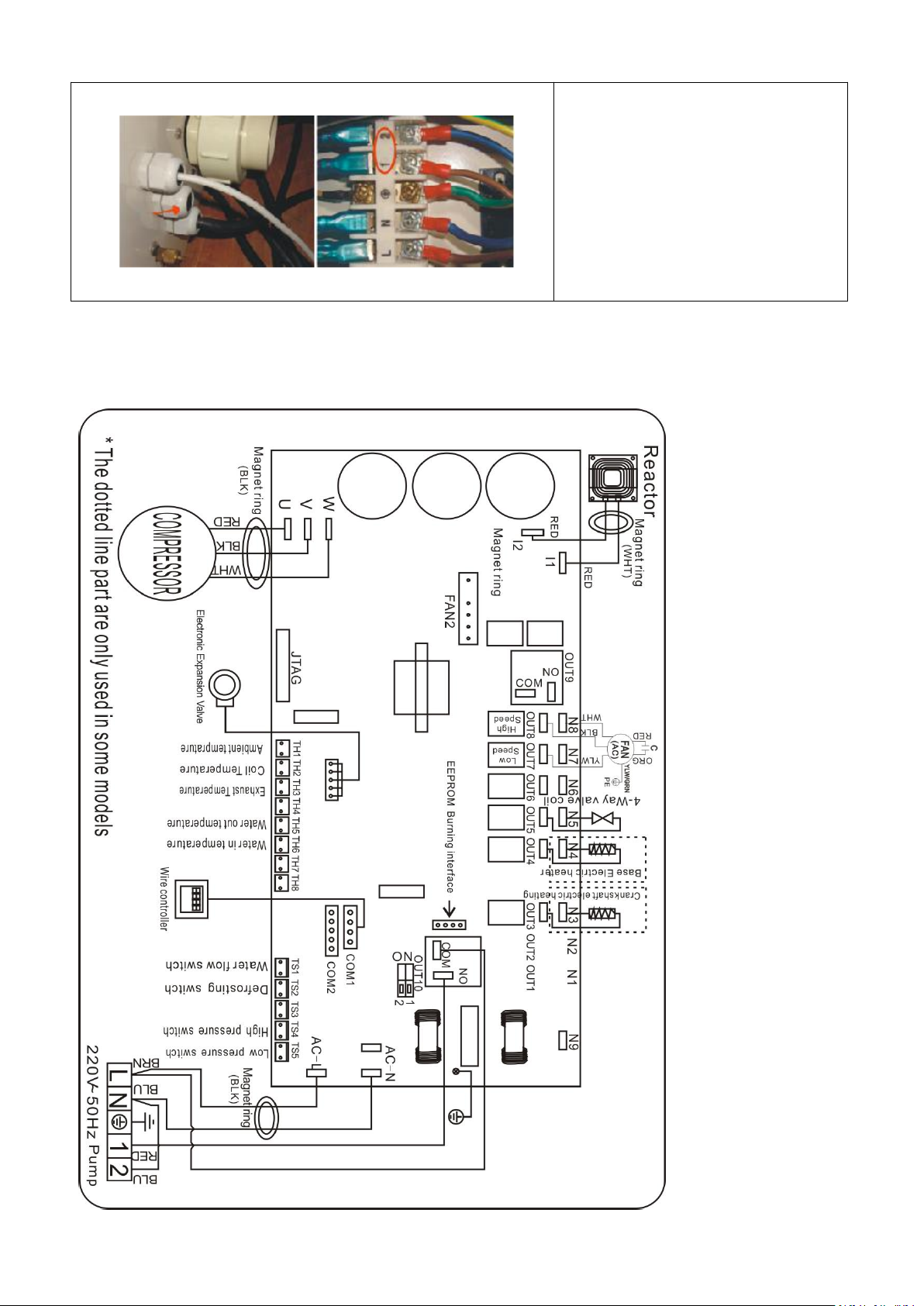
5. Electrical Wiring
5.1 SWIMMING POOL HEAT PUMP WIRING DIADRAM
Hydro-S Inverter 5/6/9/12/16/20
18
NOTE:
(1)Above electrical wiring diagram only for your reference, please subject machine posted the wiring diagram.
(2)The swimming pool heat pump must be connected ground wire well, although the unit heat exchanger is
electrically isolated from the rest of the unit .Grounding the unit is still required to protect you against short circuits
inside the unit .Bonding is also required.
Disconnect: A disconnect means (circuit breaker, fused or un-fused switch) should be located within sight of and
readily accessible from the unit .This is common practice on commercial and residential heat pumps. It prevents
remotely-energizing unattended equipment and permits turning off power at the unit while the unit is being
serviced.
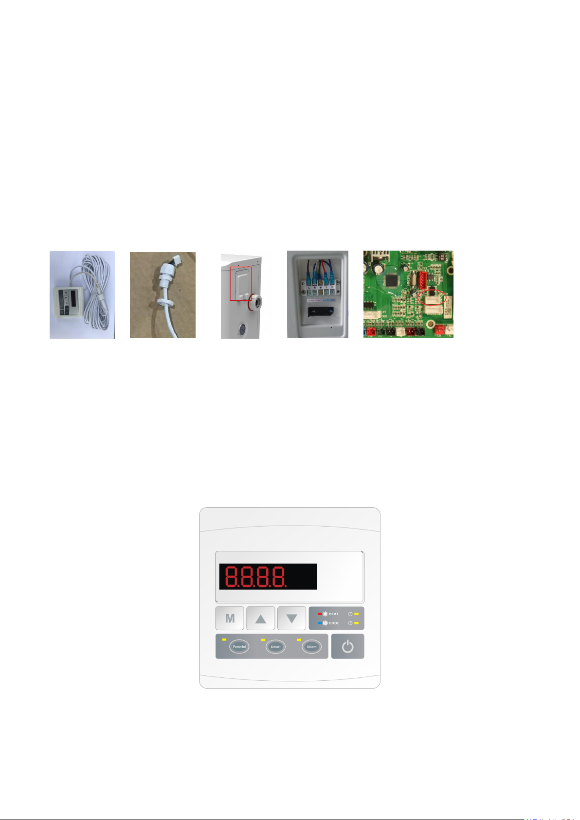
5.4 Installation of the display deportee
Photo(1) Photo(2) Photo(3) Photo(4) Photo(5)
- The side with plug connects with the control panel (photo1)
- The other side of the signal wire. (photo2)
- Open the wiring panel and put the side without plug through the electrical box. (photo3,4)
- Insert the wiring into the disignated position (code:COM 1 or COM-L) on the PC board. (photo5)
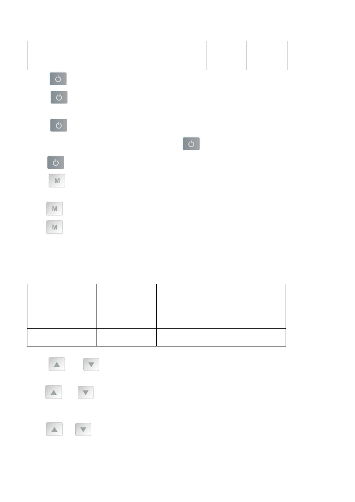
6. Display Controller Operation
6.1 The buttons of LED wire controller
6.2 The keys and their operations
NOTE: Every time, when the heat pump connects to the power, the LED display shows a code for 3 seconds which
19
indicates the heat pump model.
Model
Hydro-S
Inverter 5
Hydro-S
Inverter 6
Hydro-S
Inverter 9
Hydro-S
Inverter 12
Hydro-S
Inverter 16
Hydro-S
Inverter 20
Code
1012
1012
1016
1017
1015
1005
Set water temperature
(Tset)
Current water in
temperature
(Tset +2℃)
Current working
mode
After 3 minutes or
above, it will switch to
Tset (eg: 28℃)
Tset +2℃(eg:30℃)
Heating mode
Cooling mode
Tset (eg: 28℃)
Tset-2℃(eg: 26℃)
Cooling mode
Heating mode
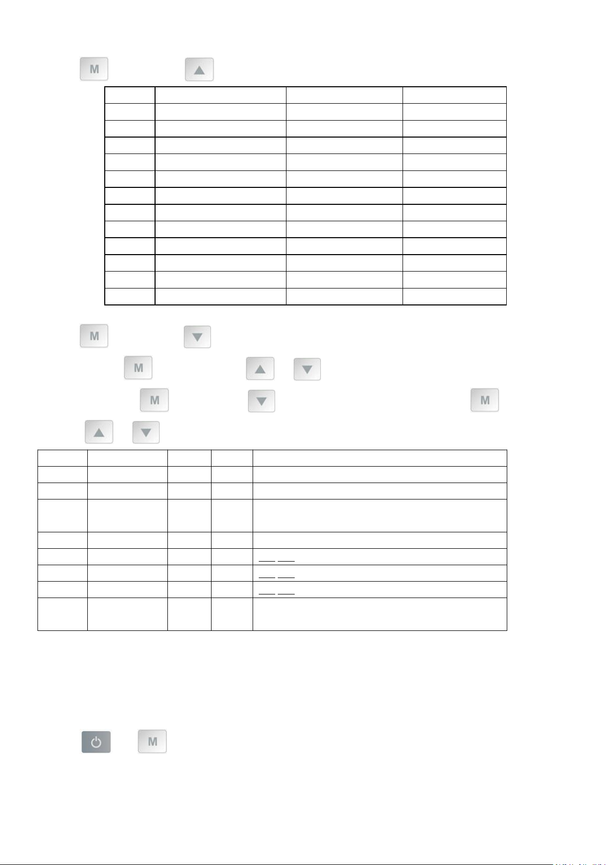
6.2.1 button
Press to start the heat pump unit, the LED display shows the desired water temperature for 5 seconds, then
shows the inlet water temperature and the operation mode.
Press to stop the heat pump unit and show “OFF”
Notice : During the parameter checking and setting, press the to quick-exit and save the current setting .
Press again to turn on/off the machine.
6.2.2 button
Automatic mode:
Press for 5 seconds to switch to automatic mode.(default:Smart mode)
Press for 5 seconds again to exit automatic mode and switch to heating mode(default:Smart mode)
Note:Under Automatic mode, it is useless to set parameter P1 .
Operation logic of Auto Mode:
6.2.3 and button
Clock/unclock the display:
Hold and for 5 seconds to lock/Unlock the display.
Water temperature setting :
Press
Parameter checking :
or
to set the water temperature directly.
20
Press first, then press to check the “ User parameter from d0 to d11
Code
Condition
Scope
Remark
d0
IPM mould temperature
0-120℃
Real testing value
d1
Inlet water temp.
-9℃~99℃
Real testing value
d2
Outlet water temp.
-9℃~99℃
Real testing value
d3
Ambient temp.
-30℃~70
℃
Real testing value
d4
Frequency limitation code
0,1,2,4,8,16
Real testing value
d5
Piping temp.
-30℃~70℃
Real testing value
d6
Gas exhaust temperature
0℃~C5℃ (125℃)
Real testing value
d7
Step of EEV
0~99
N*5
d8
Compressor running frequency
0~99Hz
Real testing value
d9
Compressor current
0~30A
Real testing value
d10
Current fan speed
0-1200 (rpm)
Real testing value
d11
Error code for last time
All error code
Code
Name
Scope
Default
Remark
P0
Manual defrost
0-101 Manual defrosting mode, 0 Normal mode
P1
Working mode
0-1
1
1 Heating mode,0 cooling mode
P2
Timer on/off
0-1
0
1 Timer on/off is under function,0 Timer on/off is out of
function (The setting of P4 and P5 won’t work)
P3
Water pump
0-101 Always running,0 Depends on the running of compressor
P4
Current time
HH:MM
00:00
0-23:0-59
P5
Timer on
HH:MM
00:00
0-23:0-59
P6
Timer off
HH:MM
00:00
0-23:0-59
P7
Inlet water temp.
correction
-9~9
0
Default setting: 0
Press first, then press to check the “ User parameter from P0 to P7
If needed, press second, then press or to adjust the current parameter.
(for example: Press first, then press to enter parameter P7 checking, and press second, then
press or to adjust the parameter P7 Inlet water temp. Correction from -9 to 9.)
NOTE: Under defrosting mode, P0=1.
After defrosting finished, it will be automatic enter Normal mode, P0=0.
6.2.4 System reset function
Press and in 10s, the system will reset and display “0000” on the controller.
21
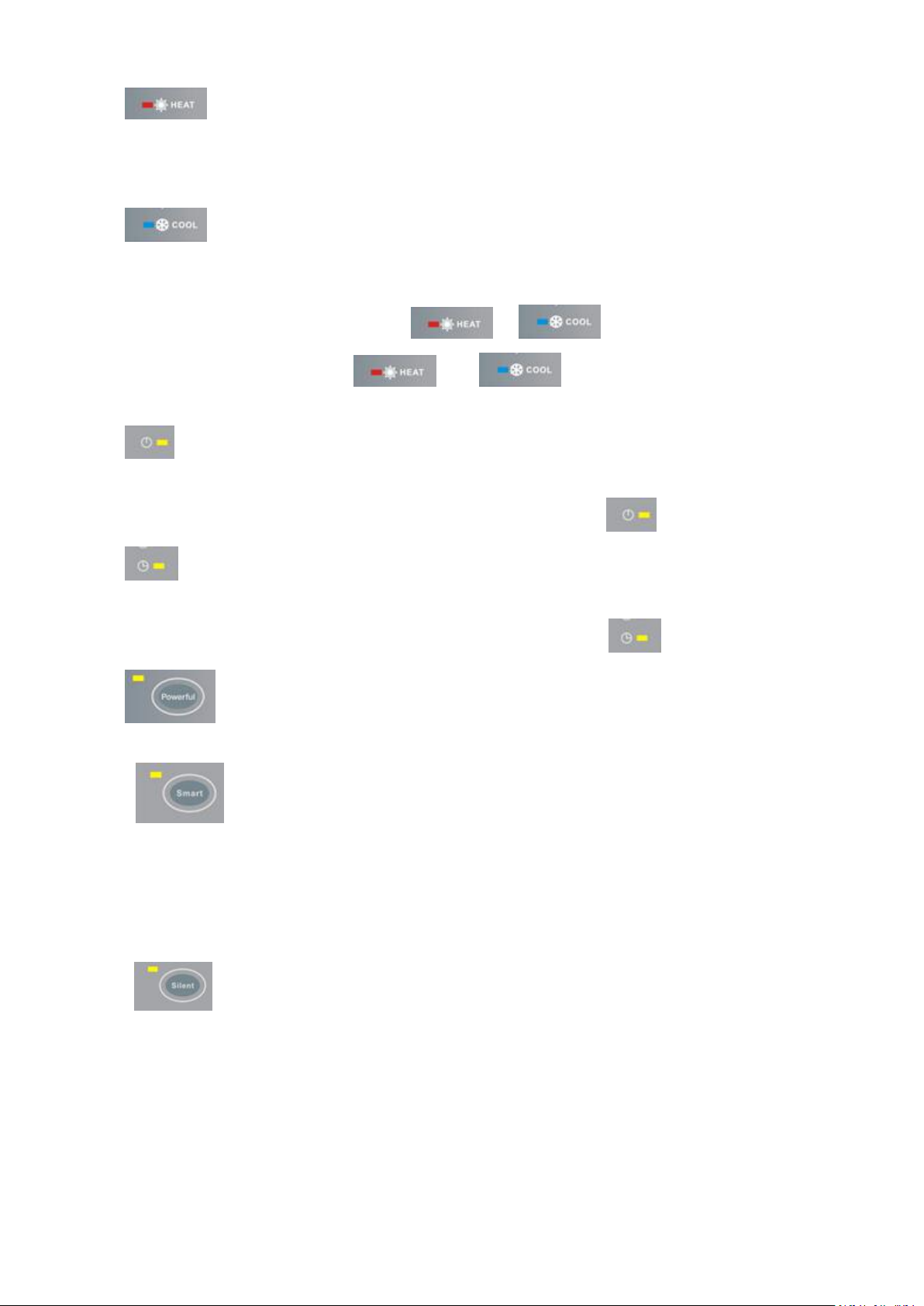
6.2.5
Symbol of heating, the light will be on when it is in operation.
When defrosting, the light will flash.
6.2.6
Symbol of cooling, the light will be on when it is in operation.
Note: When parameter P1 is on checking/adjusting, and will be flashing at the same time.
When there is on Automatic mode, and will be lighting at the same time.
6.2.7
Symbol of automatic stop, the light will be on when it is in operation.
Note: When parameter P6 is on checking/adjusting, Symbol of automatic stop light will be flash.
6.2.8
Symbol of automatic start, the light will be on when it is in operation.
Note: When parameter P5 is on checking/adjusting, Symbol of automatic start light will be flash.
6.2.9
Press this button, the light will be flash, the heat pump will operate in ‘Full output’ only.
6.2.10
While you choose the Smart, the heat pump will just operate in ‘Small output’ , ‘Medium output’ and ‘Full
output’
When in ‘Small output’, the lamp of Smart is lighting, the Silent of Powerful will be flash.
When in ‘Medium output’, the light of Smart will flash.
When in ‘Full output’, the lamp of Smart is lighting, the lamp of Powerful will be flash.
6.2.11
While you choose the Silent , the heat pump will just operate in ‘Medium output’ and ‘Small output’
When in ‘Small output’, the light of Silent will flash.
When in ‘Medium output’, the lamp of Silent is lighting, the lamp of Smart will be flash

22
7. Troubleshooting
Error Code
Malfunction
Reason
Solution
EE 01
High pressure
failure
1. High pressure switch in bad
connection or failure
2. Ambient temperature is too
high
3. Water temperature is too
high
4. Water flow is too low
5. Fan motor speed is abnormal
or fan motor has damaged
1. Check the wiring for high pressure
switch or change a new one
2.Check the water flow or water pump
3. Check the fan motor
4. Check and repair the piping system
EE 02
Low pressure failure
1. Low pressure switch in bad
connection or failure
1. EEV has blocked or pipe
system is jammed
2. Motor speed is abnormal or
motor has damaged
3. Gas leakage
1. Check the wiring for low pressure
switch or change a new one
2. Check the EEV and piping system
Check the motor
3. Through the high pressure gauge to
check the pressure value
EE 03
Water flow failure
1. Water flow switch is in bad
connection
2. Water flow switch is
damaged
3. No/ Insufficient water flow.
1. Check the wiring for water flow switch
2. Change the water flow switch
3. Check the water pump or the
waterway system
EE 04
Over heating
protection for water
temperature (T2) in
heating mode
1. Low water flow
2. Water flow switch is stuck
and the water supply is cut off
3. T2 sensor is abnormal
1. Check the water way system
2. Check the water pump or water flow
switch
3. Check T2 sensor or change another one
EE 05
Exhaust
temperature (T6)
too high protection
1. Lack of gas
2. Low water flow
3. Piping system has been
blocked
4. Exhaust temp. Sensor failure
1. Check the high pressure gauge, if too
low, fill with some gas
2. Check the waterway system and water
pump
3. Check the piping system if there was
any block
4. Change a new exhaust temp. sensor
EE 06
Controller
malfunction
1. Wire connection is not good
or damaged signal wire
2. Controller failure
1. Check and re-connect the signal wire
2. Change a new signal wire
3. Turn off electricity supply and restart
machine
4. Change a new controller
EE 07
Compressor current
protection
1. The compressor current is
too large momentary
2. Wrong connection for
compressor phase sequence
1. Check the compressor
2. Check the waterway system
3. Check if the power in the normal range
4. Check the phase sequence connection
7.1 Error code display on LED wire controller

23
3. Compressor accumulations
of liquid and oil lead to the
current becomes larger
4. Compressor or driver board
damaged
5. The water flow is abnormal
6. Power fluctuations within a
short time
EE 08
Communication
failure between the
controller and the
main board
1. Poor signal wire connection
or damaged signal wire
2. Controller malfunction
1. Check and re-connect the signal wire
2. Change a new signal wire
3. Turn off electricity supply and restart
machine
4. Change a new controller
EE 09
Communication
failure between
Main board and
driver board
1. Poor connection of
communication wire
2. The wire is damaged
1. Check the wire connection
2. Change a new wire
EE 10
VDC voltage too
high protection
1. Mother line voltage is too
high
2. Driver board is damaged.
1. Check if the power is in the normal
range
2. Change driver board or main board
EE 11
IPM module
protection
1. Data mistake
2. Wrong compressor phase
connection
3. Compressor liquid and oil
accumulation lead to the
current becomes larger
4. Compressor or driver board
damaged
1. Program error, turn off electricity
supply and restart after 3 minutes
2. Change driver board
3. Check compressor sequence
connection
EE 12
VDC voltage too low
protection
1. Mother line voltage is too
low
2. Driver board is damaged.
1. Check if the power is in the normal
range
2. Change driver board
EE 13
Input current over
high protection.
1. The compressor current is
too large momentary
2. The water flow is abnormal
3. Power fluctuations within a
short time
4. Wrong PFC inductor
1. Check the compressor
2. Check the waterway system
3. Check if the power is in the normal
range
4. Check if the correct PFC inductor is
used
EE 14
IPM module
thermal circuit is
abnormal
1. Output abnormity of IPM
module thermal circuit
2. Fan motor is abnormal or
damaged
3. Fan blade is broken
1. Change a driver board
2. Check if the motor speed is too low or
fan motor damaged, change another one
3. Change another fan blade

24
EE 15
Temperature of IPM
module is too high
1. Output exception of IPM
module thermal circuit
2. Motor is abnormal or
damaged
3. Fan blade is broken
1. Change a driver board
2. Check if the fan motor speed is too low
or fan motor damaged, change another
one
3. Change another fan blade
EE 16
PFC module
protection
1. Output exception of PFC
module
2. Motor is abnormal or
damaged
3. Fan blade is broken
4. Input voltage leap, input
power is abnormal
1. Change a driver board
2. Check if the motor speed is too low or
fan motor damaged, change another one
3. Change another fan blade
4. Check the input voltage
EE 17
DC fan motor failure
1. DC motor is damaged
2. Main board is damaged
3. The fan blade is stuck
1. Detect DC motor, replace with a new
one
2. Change a new main board
3. Find out the barrier and work it out
EE 18
PFC module
thermal circuit is
abnormal
The driver board is damaged
1. Change a new driver board
2. Check if the fan motor speed is too low
or fan motor damaged, change another
one
EE 19
PFC module high
temperature
protection
1. PFC module thermal circuit
output abnormal
2. Motor is abnormal or
damaged
3. Fan blade is broken
4. The screw in the driver board
is not tight
1. Change a new driver board
2. Check if the motor speed is too low or
fan motor damaged, change another one
3. Change another fan blade
4. Check if the screw is loose
EE 20
The input power
failure
Power supply voltage fluctuates
too much
Check whether the voltage is stable
EE 21
Software control
exception
1. Compressor run out of step
2. Wrong program
3. Impurity inside compressor
causes the unstable rotate
speed
1. Check the main board or change a new
one
2. Enter correct program
EE 22
Current detection
circuit failure
1. Voltage signal abnormal
2. Driver board is damaged
1. Check the main board or change a new
one
2. Change a new driver board
EE 23
Compressor startup
failed
1. Main board is damaged
2. Compressor wiring error or
poor contact or unconnected
3. Liquid accumulation inside
4. Wrong phase connection for
compressor
1. Check the main board or change a new
one
2. Check the compressor wiring according
to the circuit diagram
Check the compressor or change a new
one
EE 24
Ambient
Temperature device
failure on Driver
Ambient Temperature device
failure
Change driver board or main board

25
board
EE 25
Compressor phase
failure
Compressors U, V, W are
connected to one phase or two
phases
Check the actual wiring according to the
circuit diagram
EE 26
Four-way valve
reversal failure
1. Four-way valve reversal
failure
2. Lack of refrigerant (no detect
when T3 or T5 malfunction)
1. Switch to Cooling mode to check the
4-way valve if it has been reversed
correctly
2. Change a new 4-way valve
3. Fill with gas
EE27
EEPROM data read
malfunction
1. Wrong EEPROM data in the
program or failed input of
EEPROM data
2. Main board failure
1. Re-enter correct EEPROM data
2. Change a new main board
EE28
The inter-chip
communication
failure on the main
control board
Main board failure
1. Turn off electricity supply and restart it
2. Change a new main board
PP 01
Inlet water
temperature sensor
failure
1. The sensor failure or short
circuit
2. The wiring of sensor is loose
1. Re-fix the wiring of the sensors
2. Change the sensor
PP 02
Outlet water
temperature sensor
failure
1. The sensor failure or short
circuit
2. The wiring of sensor is loose
1. Re-fix the wiring of the sensors
2. Change the sensor
PP 03
Heating piping
sensor failure
1. The sensor failure or short
circuit
2. The wiring of sensor is loose
1. Re-fix the wiring of the sensors
2. Change the sensor
PP 04
Gas return sensor
failure
1. The sensor failure or short
circuit
2. The wiring of sensor is loose
1. Re-fix the wiring of the sensors
2. Change the sensor
PP 05
Ambient
temperature sensor
failure
1. The sensor failure or short
circuit
2. The wiring of sensor is loose
1. Re-fix the wiring of the sensors
2. Change the sensor
PP 06
Exhaust piping
sensor failure
1. The sensor failure or short
circuit
2. The wiring of sensor is loose
1. Re-fix the wiring of the sensors
2. Change the sensor
PP 07
Antifreeze
protection in
Winter
Ambient temperature or water
inlet temperature is too low
Normal protection
PP 08
Low ambient
temperature
protection
1. Beyond the scope of using
environment
2. Sensor abnormality
1. Stop using, beyond the scope of using
2. Change the sensor
PP 10
Piping temperature
too high protection
under cooling mode
1. Ambient temperature is too
high or the water temperature is
too high in cooling mode
2. Refrigeration system is
abnormal
1. Check the scope of using
2. Check refrigeration system

26
PP 11
Water temperature
(T2) too low
protection under
cooling mode
1. Low water flow
2. T2 temperature sensor
abnormal
1. Check water pump and waterway
system
2. Change T2 temperature sensor
7.2 Other Malfunctions and Solutions (No display on LED wire controller)
Malfunctions
Observing
Reasons
Solution
Heat pump is
not running
LED wire controller
no display.
No power supply
Check cable and circuit
breaker if it is connected
LED wire controller.
displays the actual time.
Heat pump under standby
status
Startup heat pump to run.
LED wire controller
displays the actual
water temperature.
1. Water temperature is
reaching to setting value, HP
under constant temperature
status.
2. Heat pump just starts to
run.
3. Under defrosting.
1. Verify water temperature
setting.
2. Startup heat pump after a
few minutes.
3. LED wire controller should
display "Defrosting".
Water
temperature is
cooling when HP
runs under
heating mode
LED wire controller displays
actual water temperature
and no error code displays.
1. Choose the wrong mode.
2. Figures show defects.
3. Controller defect.
1. Adjust the mode to proper
running
2. Replace the defect LED wire
controller, and then check the
status after changing the
running mode, verifying the
water inlet and outlet
temperature.
3. Replace or repair the heat
pump unit
Short running
LED displays actual water
temperature, no error code
displays.
1. Fan NO running.
2. Air ventilation is not
enough.
3. Refrigerant is not enough.
1. Check the cable connections
between the motor and fan, if
necessary, it should be
replaced.
2. Check the location of heat
pump unit, and eliminate all
obstacles to make good air
ventilation.
3 Replace or repair the heat
pump unit.
water stains
Water stains on heat pump
unit.
1. Concreting.
2. Water leakage.
1. No action.
2. Check the titanium heat
exchanger carefully if it is any
defect.
27
Too much ice on
evaporator
Too much ice on
evaporator.
1. Check the location of heat
pump unit, and eliminate all
obstacles to make good air
ventilation.
2. Replace or repair the heat
pump unit.
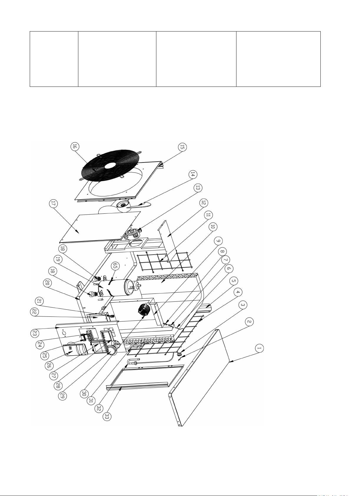
8. Exploded Diagram and Maintenance
8. 1 Exploded Diagram
Hydro-S Inverter 5/6/9
 Loading...