

HYDRO-RAIN HRC 100-C 96054, HRC 100-C 96057, HRC 100-C 96058, HRC 100-C 96059 User Manual
PN 96054-24 rB
USER'S MANUAL
RESET
PROGRAM
RAIN DELAY
AUTO
OFF
SET
CLOCK
SET
DATE
BUDGET
HOW
OFTEN
RUN
TIME
START
TIME
Models:
HRC 100-C (96054) 4-Station Update all titles to Indoor/Outdoor Mount, Irrigation Controller
HRC 100-C (96057) 6-Station Update all titles to Indoor/Outdoor Mount, Irrigation Controller
HRC 100-C (96058) 9-Station Update all titles to Indoor/Outdoor Mount, Irrigation Controller
HRC 100-C (96059) 12-Station Update all titles to Indoor/Outdoor Mount, Irrigation Controller

2

Table of Contents
Section 1: Get to know your HRC 100 C.............4
Section 2: Installation ...........................5
Section 3: Programming with Easy-Set Logic™.......9
Section 4: Additional Features ...................11
Section 5: Reference ...........................13
3
Congratulations on selecting your new
Hydro-Rain irrigation controller! With
Hydro-Rain’s exclusive Easy-Set Logic™,
simple programming and setup are
combined with the latest controller
technology and versatility.
Your HRC 100 C provides convenience
and flexibility, letting you run a fully
automatic, a semi-automatic, or a manual
watering program for all your watering
needs. Although this controller is so easy
to program that you likely will not need
instructions, we recommend that you read
this manual fully before installation so that
you understand all of the advanced features.
4
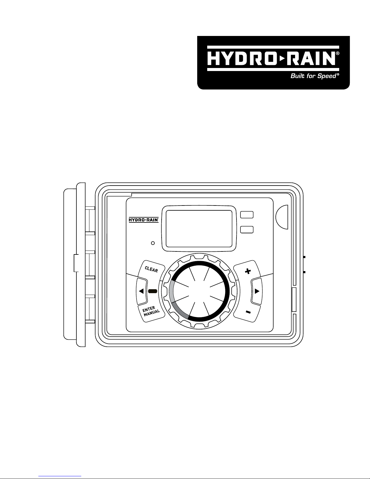
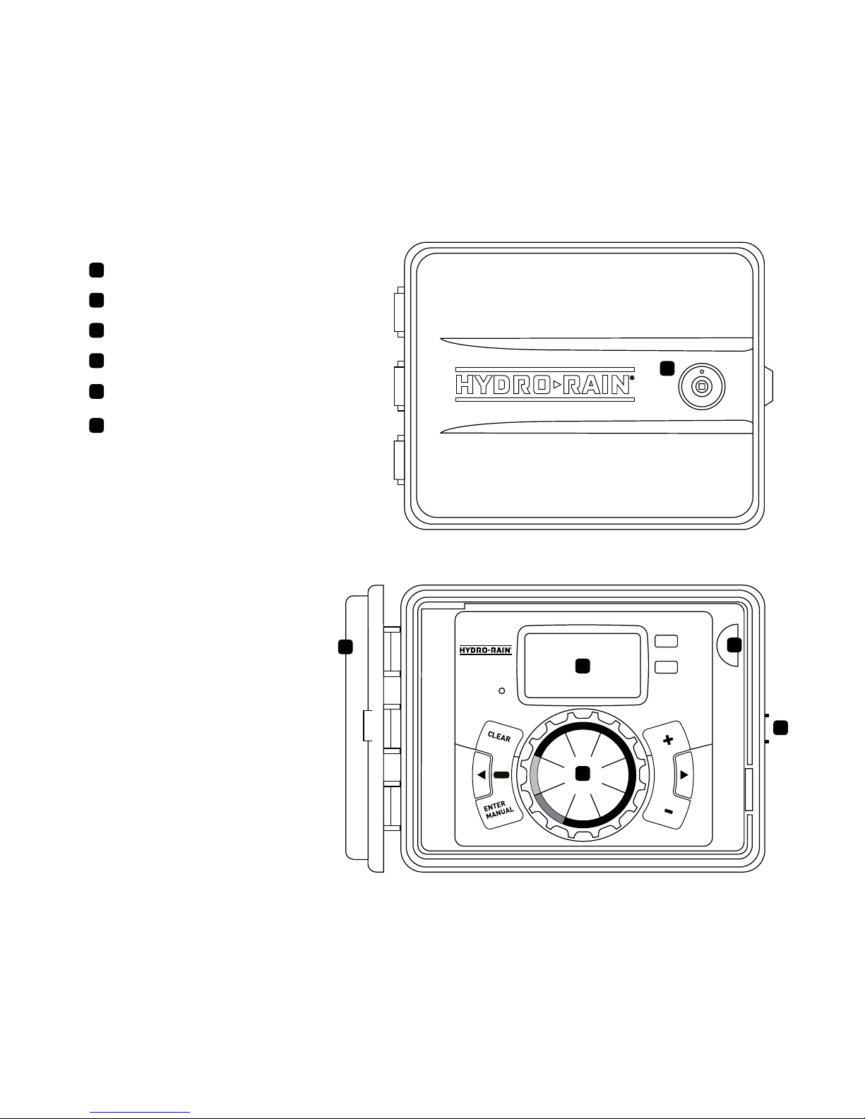
A
B
C
D
E
Lock and latch
Weather Resistant Cover
Dial
Digital Display
Battery Compartment
Swing Door panel
F
RESET
PROGRAM
RAIN DELAY
AUTO
OFF
SET
CLOCK
SET
DATE
BUDGET
HOW
OFTEN
RUN
TIME
START
TIME
Section 1: Get to know your HRC 100 C
A
B
C
D
E
F
5
Buttons Function
ENTER
MANUAL
To confirm a new setting
To water manually
CLEAR To clear a setting
PROGRAM To move to different programs: A, B, and C
ARROW [ ]
To skip to the next setting / watering station
or move to other programs/settings
ARROW [ ]
To go back to the previous setting / watering
station or move to other programs/settings
RAIN DELAY
To pause operation for 24-72 hours due
to rain or other factors
[ + ] To increase a numeric setting
[ – ]
To decrease a numeric setting and to
select “Manual TEST ALL” programming
(see instructions)
Dial Position Function
RUN Set Program is operating automatically
SET CLOCK Set current time
SET DATE Year, Month, and Day
START TIME Set time to begin watering
RUN TIME Set watering duration for each station
HOW OFTEN Set frequency of watering days
BUDGET Adjust overall watering as a percentage
OFF Turn all stations/functions off
Section 2: Installation
Required Tools
• Phillips Screwdriver
• Wire Strippers
Installation Steps
1. Select a Location
2. Mount the Controller
3. Connect Valve Wires to Controller
4. Connect Electrical Power
5. Activate Battery
6
1. Select a Location
When choosing a location for your HRC 100 C,
consider the following:
• Choose location near a power source (if hard wiring) or
electrical outlet when using the supplied power cord.
• Ensure operating temperatures are not below 0° Celsius
or above 70° Celsius.
• Place it away from direct sunlight if possible.
• Ensure at least 23 cm of space to the left of the
sprinkler controller box for the door to swing open after
installation.
• Locate the controller where there is easy access to
sprinkler wire (from valves). If mounted in an outdoor
location, shut the compartment door to keep the
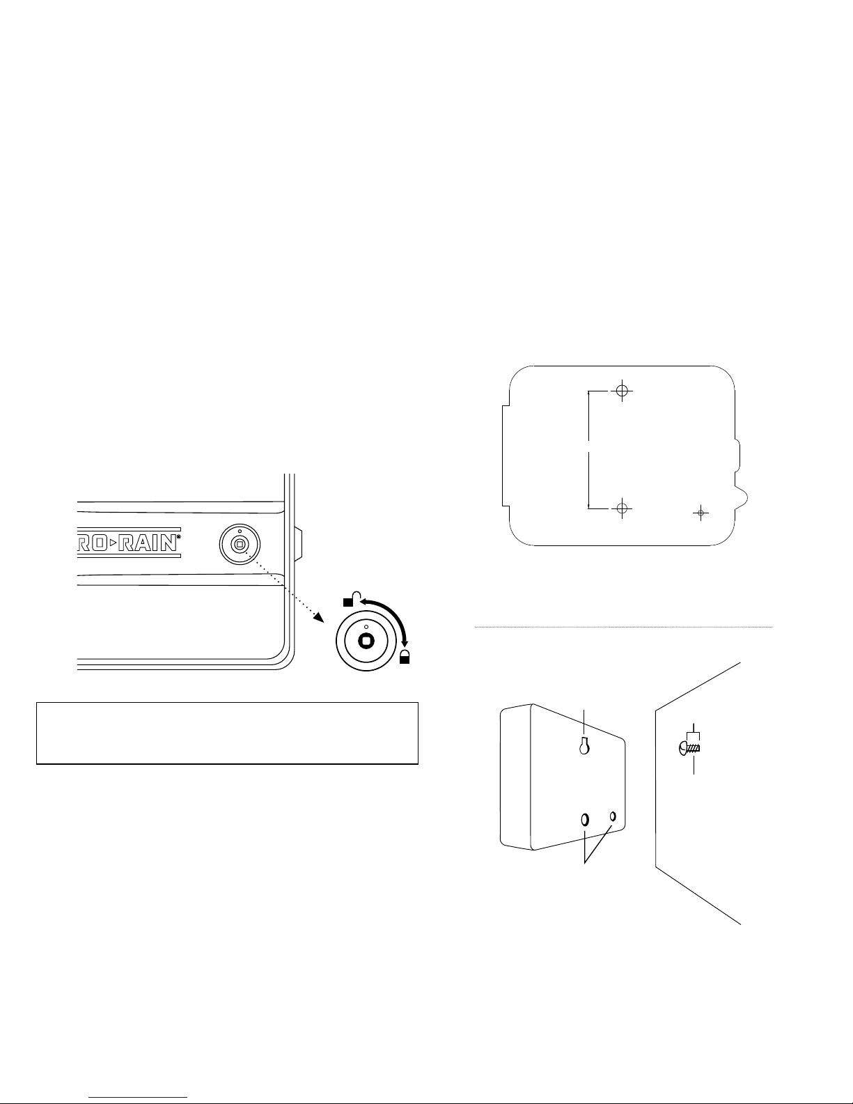
controller safe from weather damage. To lock: insert the
key and turn clockwise to the locked position.
Note: Sprinkler controllers are weather-resistant to UL-50
and ETL® Listings, but should not be placed in areas where
continuous water could cause damage.
2. Mount the Controller
• Use the mounting template (included) to mark the
mounting screw location on the wall. See Figure 1
• Install a No. 8 screw (included) into wall in the upper
template location. Leave the screw head protruding
3 mm from wall. Use expanding anchors (included) in
plaster or masonry, if necessary, for a secure hold.
• Slip the HRC 100 C over protruding screw (using keyhole
slot in back). See Figure 2
• Drive a No. 8 screw through one of the two pre-formed
holes located in lower back cabinet. See Figure 2
Figure 2: Hang timer on screw using keyhole
Keyhole
Pre-formed
mounting holes
No. 8 Screw
Wall
3 mm
MOUNTING TEMPLATE
106 mm
Figure 1: Use Mounting Template (included)
 Loading...