

HydroQuip ES8848A, ES8848C, ES8848D, ES8848E, ES8848J Installation & Operation Manual
...
Outdoor Series
INSTALLATION
& OPERATIONS
MANUAL
Covers the following CS & ES Models:
ES8848A, ES8848B, ES8848C, ES8848D, ES8848E,
ES8848J, ES8848H, ES8848J, ES8850A, ES8850B,
ES8850C, ES8850D, ES8850E, ES8850F, ES8850G,
ES8850H, ES8850J, CS8800A, CS8800B, CS8800C
JL
To ensure that the system is installed
properly, provide your electrician with
these instructions.
8800 BP Series

TABLE OF CONTENTS
Getting Started 1
Terms / Glossary 2-3
System Requirements & Considerations 4-5
NEC Guidelines & Gas/Electric Combination Systems 6-7
Electrical System Sizing 8
GFCI Breaker Wiring 9
Connecting Power to the System 10-14
Wiring Individual Components 15
Gas Heater Options 16
Pump Cord Connections 17
Air Blower Installation & System Configuration 18
Spa Light Wiring 19
Plus Ozone™ / Ozonator / Installation 20-21
Spaside Control Installation 22
Wi-Fi Module Installation 23
System Configuration Options 24-25
Your Spaside Control / Menu Navigation 26-27
System Start Up 28
System Functions, Features & Programming 29-32
Locking and Unlocking Spaside 33
Spaside Messages, Error Codes & Troubleshooting 34-41
System Data Label 42
Warranty Information 43

GETTING STARTED
For the best installation possible, review all the provided instruction materials, and share
with your electrician/installer for advanced planning. A complete understanding of what's
needed before starting work will make things go smoothly, and at the lowest possible
cost.
This manual includes complete instructions for electrical and plumbing connections,
including the addition of pumps, gas heaters, lights, system startup, troubleshooting,
and your warranty guidelines.
First identify the Equipment System (ES) or Control System (CS) from your product
label. Refer to this code when using the GFCI breaker sizing matrix, and wiring diagrams
in this manual
ES series controls include a plastic mounting base, and main system pump. The
separate quick –start sheet #85-0115-4 has detailed instructions for pack assembly, and
pump cord installation
CS series controls are designed for a wall mount application. Your electrician must follow
all local codes and restriction pertaining to placement of an accessible electrical service.
* Copies of this manual are available online at www.hydroquip.com
Your Hydro-Quip 8000 series control has a factory pre set program. Details for changing
system behavior and/or adding new components will be found in this manual.
ATTENTION!
This manual includes instructions for all options available on the ES/CS systems.
Depending on how your system is equipped, some options like Plus Ozone™, Wi,
blowers, gas heaters etc may not apply to your installation.
Warning! Make no attempt to modify, disconnect, damage or adjust the safety devices
contained in this equipment system. Alteration of safety devices can cause serious
component damage, and/or result in unsafe operation leading to personal injury or death
Save a copy of this manual
1

TERMS / GLOSSARY
AC Connection
Additional Panel Button
Amperage Requirement
AUX PCB
Auxiliary Pump
Blower
Bonding Wire
™
BWA APP
Copper Conductors
Dedicated Circuit
Default Programming
Dip Switch
Dip Switch Banks
Discharge
Alternating Current connection point (typically high voltage)
Refers to HQ PT# 34-0224. Required for 3rd pump operation
The accumulated total amperage of all items to be placed on a
single breaker
Smaller daughter board connected to main PCB
A pump that has been added to the original equipment system (ie Aux
pump #2 & #3)
Appliance providing compressed air for the purpose of massage therapy
Continuous bare copper wire connecting all metallic object and electrical
components to the equipment & ground rod
Downloadable Balboa Water Application for wireless system control
Electrical wires made from copper alloy materials
An electrical supply to a remote location, having breaker protection and
no additional branch or service connections
The standard position or programming in which the system is tested
and leaves the factory
Movable programming switch located within a switch-bank (on PCB)
Set of switches used to change operational logic and system behavior
(on PCB)
Pump exit side (piping placed on pressure side of pump)
Dual Source Wiring
Gas Heater Control Circuit
GFCI Breaker
GFCI breaker #1
GFCI breaker #2
Heater Input Leads
Jumper Pins
Electrical power supplied by two individual wiring sources (two breakers)
Wiring provided inside gas heaters, that can be connected to 8000
systems for operational control. Commonly called a fireman circuit
Ground Fault Circuit Interrupter. Specialty breaker with a detection and
reaction device to interrupt power when current leaking is detected to
ground
Main 8000 system breaker, required 4 wires with incorporated “Neutral”
Optional breaker for independent heater operation. Required 3-wire
connection, without “Neutral”
Provided wires for connection of heaters in the dual source
configuration
Circuit board electrical posts for logic changes.
2

TERMS / GLOSSARY
KW
Line of Sight
Logic Jumper
Liquid Tight Conduit
Main Control
Main Pump or Pump #1
NEC
PCB
Persistent Memory
Plus Ozone™/Ozonator
Priming
Pump Amperage
Pump Pot/Basket
Single Source Wiring
Kilowatt. Heater resistance rating used for identifying energy consumption.
A clear and unobstructed path, in which an object or item can be spotted from
or near the spas edge.
Movable coupling located on the jumper pins for changing operational
behavior
Tubing that resists water and debris penetration, made specifically for
wiring
In reference to the 8000 series control box, with factory provided components
System provided pump used for heating and filtration
National Electrical Code. Regulations for design and materials on electrical
installation.
Printed Circuit Board (refers to main board)
Programming that remains unchanged, until the power is turned off and back
on
Appliance designed for spa water sanitation
Initial pump operation until the air is evacuated from the pump and supply
lines
The highest amperage measured, when the pump is under full load
condition
Reservoir mounted to the pump with removable lid and strainer basket
Electrical power supplied by a single wiring source and breaker
(one breaker)
Sub Panel
Suction
System Data Label
System Disconnect
Terminal Strip
Total System Amps
Wi-Fi Enabled
An electrical service box mounted remotely from the main house power panel
Pump front inlet side (piping between spa suctions and pump pot)
Label placed on control box providing serial identification, and vital data
An easy and safe means of 100% electrical disconnection, without
obstruction or the need for tools. See NEC and UL qualifications for approved
devices.
Electrical connection point for components within the PCB cabinet
Highest amperage measured when all components are operating
simultaneously
Having the capacity to control using a wireless connection
3
SYSTEM INSTALLATION REQUIREMENTS
The Hydro-Quip 8000 Series Solid-State Systems were designed for indoor or outdoor installations.
This equipment may be used for both inground and above ground spas/hot tubs.
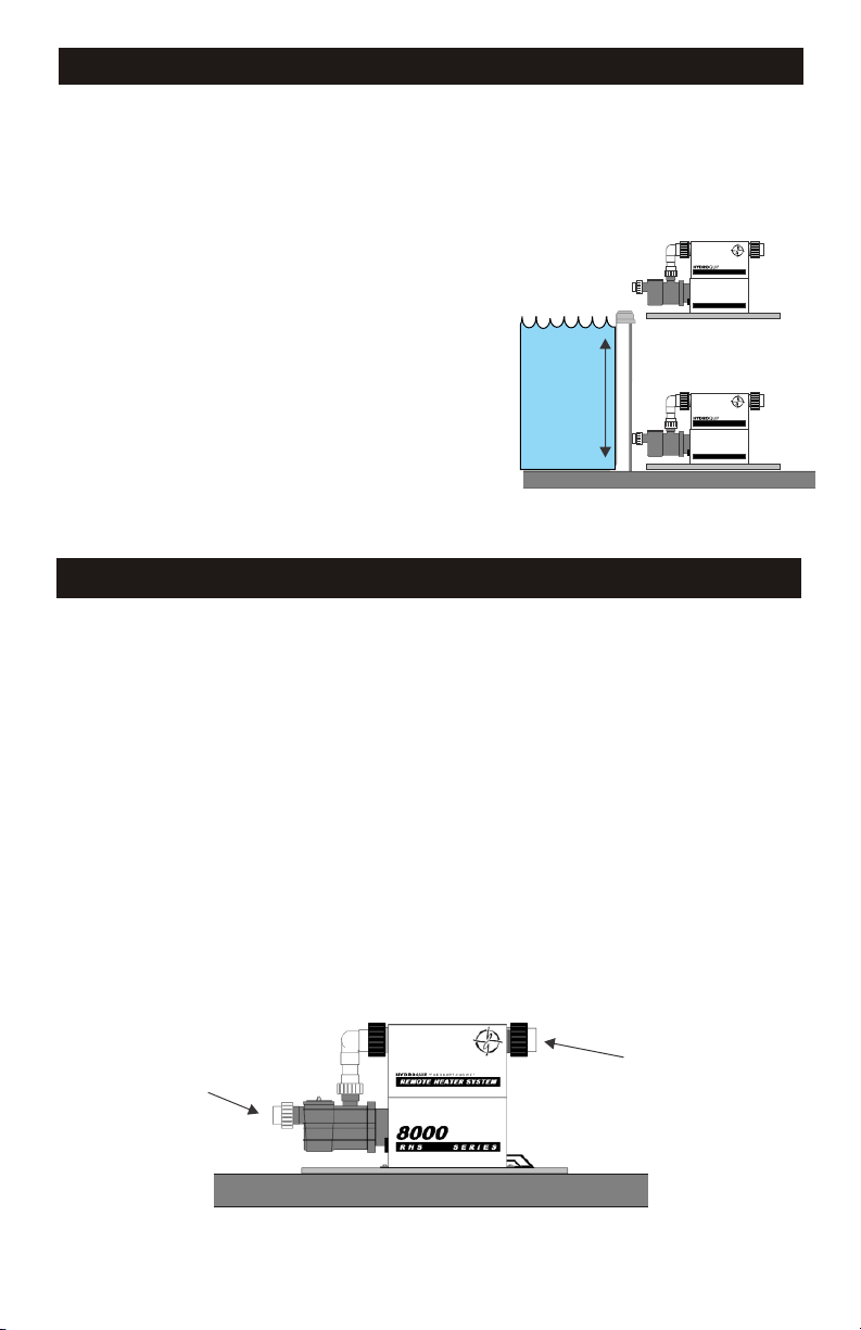
The Equipment System must be installed on a firm, level
surface (ie: concrete or plastic base)
The area where the system is installed must have adequate
Above Water Level
drainage to prevent flooding of the equipment under all
circumstances.
For performance reasons locate the system as close to the
spa/hot tub as practical. (Consult local codes for minimum
REMOTE HEATER SYSTEM
8000
RHS SERIES
distance between equipment and spa)
Provide adequate access around and above the System for
service and maintenance. Three (3’) of clearance around the
equipment is recommended.
The pump(s) provided with the system may or may not be
self-priming. Pumps that are NOT self priming must be
installed BELOW water level or they will not prime.
The Spaside control has a 50’ cord length. Plan routing
distance between the equipment and vessel to be less than
44ft.
Water Level
REMOTE HEATER SYSTEM
8000
RHS SERIES
Below Water Level
(Flooded Suction)
PLUMBING INSTALLATION INSTRUCTIONS
To assure adequate performance, the use of 2” piping is recommended.
There may be 3 or 4 separate plumbing systems in the spa. Verify the function of each pipe.
1) Suction System Plumbing - this plumbing will connect to the spa’s skimmer, main drain and
suction fittings. This plumbing connects to the front end of each pump.
2) Discharge System Plumbing - this plumbing will go to the spa’s hydrotherapy jet and massage
fittings. This plumbing connects to the open end of the heater on your Equipment System.
3) Air Blower Plumbing - this plumbing will go to an air channel under the floor, or to an air distribution
manifold of the spa. This plumbing connects only to an air blower.
4) Aux Pump Plumbing - When more pumps are added, this piping will not interconnect with the
heater control system. Follow the spa/hot tub manufactures instruction for connection, and safety
suction requirement
5) Understand in advance the spa manufactures plumbing design for ozone delivery and make
accommodation in your plumbing plan.
To allow for safe operation of the spa/hot tub, the suction fittings must be agency approved and rated
Max Flow capacity.
After plumbing is complete, secure the Hydro-Quip Equipment System with the appropriate
hardware.
Suction
Discharge
Refer to plumbing schematic Fig.1 on page 15
4

INSTALLATION CONSIDERATIONS
The Hydro-Quip 8000 series incorporates the most advanced controls in the industry, and
are designed for years of trouble free operation. However, for year round success, review
these design recommendations for extreme weather areas.
*For best results, review this manual completely before starting your project.
Hot weather conditions
Water temperatures can be elevated from high outside “ambient” temperatures. If this
occurs, remove the insulating cover and add cool water until the heat has dissipated to a
safe level
Hot temperatures and/or direct sunlight to the equipment system can cause temporary
operational problems.
Pumps are equipped with special overload devises to self protect when encountering
extreme heat conditions. All motors are equipt with an automatic reset device, and will
resume operation when they become cool. Pumps can be enclosed, but require adequate
ventilation
Direct sunlight on equipment can bring temperatures beyond the allowable point for
circuits to function correctly. The system will shut off into a protection mode (see
troubleshooting guide.) To prevent this condition, plan an equipment cover that
incorporates shade, access and ventilation
Freezing weather conditions
If you wish to utilize/operate your system during seasons that may experience freezing
temperatures, please incorporate pipe insulation, draining capabilities and incorporate
an equipment cover that protects from snow and freezing rain. In all cases standing water,
and snow should not be allowed to accumulate in or around the equipment.
If you wish to winterize your spa/hot tub, please contact your spa/hot tub manufacturer or
local area pool/spa/hot tub professional for details.
In all cases make a plan for system draining in case of a power loss. Where possible,
design plumbing drains and disconnects to evacuate water before it becomes frozen and
does system damage.
Note the 8000 systems incorporate a freeze sensing technology, that will automatically
operate the pumps when temperatures drop below 43F. Moving the water will not allow
pipes and equipment to form ice.
5

ELECTRICAL INSTALLATION
NOTICE! Before attempting installation of this equipment system, read all the
information contained in this manual, and confirm the installing electrician understands
and follows all national and local codes and safety instructions.
All connections must be made by a qualified and licensed electrician in accordance with
the National Electrical Code (NEC article 680 Canadian Electric Code, and with any local
codes in effect at the time of installation.
All connections must be made according to the electrical installation label on the outside
of the system box (see page 33) Follow all instructions provided in this manual, and at
labeled connections. If your electrician in unclear on how to correctly connect this
equipment, call your system supplier. Note that damage caused by mistakes can be
costly, and invalidate your warranty.
A GFCI (Ground fault circuit interrupter) breaker is a mandatory electrical device required
for installation on all pool/spa applications as specified in the National Electrical Code
Article 680-42.
The GFCI must be properly sized, and be connected with the appropriate sized wire per
NEC Code Table 310-16. All ground wires must be connected per NEC Table 250-122
Follow the instructions provided in this manual (see pages 7-9) for proper location and
connection of this safety device
This equipment requires a dedicated electrical supply circuit, with no other appliances or
lights connected.
IMPORTANT – The NEC and most local codes require that an electrical “disconnect” be
installed within “line of site” of the spa
Use copper conductors only, with grounding wire properly sized per the National Electric
Code table 250-95.
A bonding lug has been provided on the control box, allowing connection to local ground
points. To reduce the risk of electrical shock, use only a properly sized copper bonding
wire from this lug to all metal ladders, water pipes and other metallic objects within 5 feet
of the spa/hot tubs edge.
CAUTION: Do not connect or disconnect any components while the power is on.
All connections must be done with the power off as it may cause damage to the
system.
**Any resulting damages are not covered under manufacturer’s warranty**
CAUTION: Damage may occur to the circuit board and spaside if the spaside
plug is not properly aligned to the receptacle on the circuit board or if the
spaside plug is connected or disconnected while the power is on.
**Any resulting damages are not covered under manufacturer’s warranty**
6

ELECTRICAL INSTALLATION
This equipment system has been100% factory tested for quality and reliability prior to
shipping. Care should be taken on all electrical connections to avoid damage to the system
circuit board, and added components. Damage caused by accidents, improper wiring
configurations and/or abuse voids your warranty.
Start by having your electrician select a wiring configuration that best fits your total system
needs. (see the GFCI breaker sizing matrix on page 8)
Due to the availability of GFCI breaker sizes, and your electrical supply requirement, some
systems require a second independent or “dual” power source, to supply the electric heater
separately. Diagrams for independent heater wiring are provided in this manual.
Note; 5.5kw systems using a single source power supply will not allow electric heater
operation when pumps are in high speed. See system programming to change operation if
available.
System Type Heater size Connection type
Gas heat none Single source power supply
Electrical heat 5.5kw Single source power supply
Electrical heat 5.5kw Dual source power supply
Electrical heat 11.0kw Dual source power supply
Gas/Electric Combo 5.5 or 11kw/Gas Single Source power supply
All Hydro-Quip 8000 series control systems require a 4 wire electrical supply, incorporating
a “Neutral” wire for operation. Electric heaters being powered independently in the “dual”
circuit configuration do not require a neutral wire supply. This is clearly explained in the
wiring diagrams.
For gas heaters electrical connection, consult your gas heaters supplier manual, and note
in this manual contains important wiring instructions for control and operation of the gas
heaters fireman circuit.
Gas and electric heater combination
When faster heat recovery is desired, or a redundant heat source is a priority, it’s possible
to install both a gas and electric heater on the same 8000 series system.
Default programming allows both the gas heater control circuit (page 15) and electric
heater circuit to operate simultaneously. Input from both heat sources will speed up heating
times, and also provide an operating alternate if one source becomes disabled. You must
follow all installation instructions for both the gas heater, and electric heater plumbing and
wiring requirements to successfully connect. No PCB programming change is required.
7
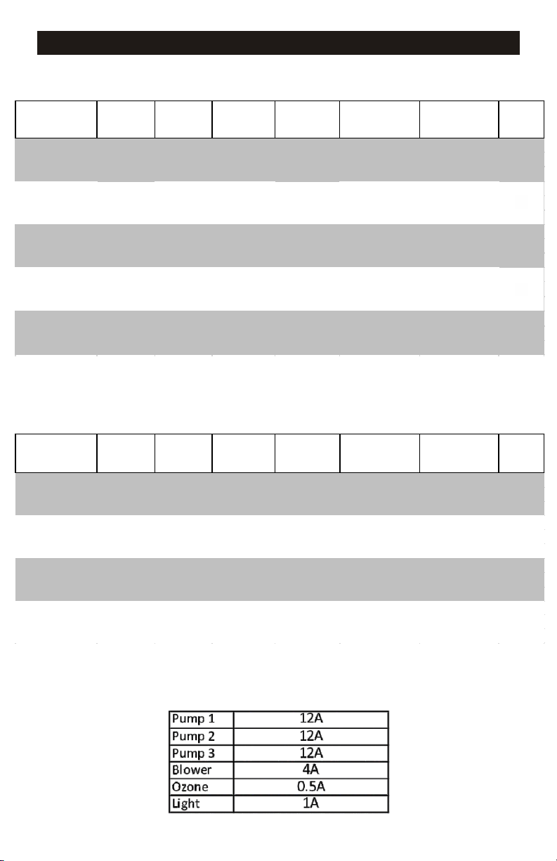
GFCI BREAKER SIZING MATRIX
240V Single source wiring (One breaker required)
Syste m or de r
code on labe l
ES8848G, H, J
ES8850G, H, J
CS8800C
ES8848G, H, J
ES8850G, H, J
CS8800C
ES8848G, H, J
ES8850G, H, J
CS8800C
ES8848D, E
ES8850D, E
CS8800B
ES8848D, E
ES8850D, E
CS8800B
Syste m
heater type
Gas x _ _ 17
{
Gas x
{
Gas x x x
{
5.5kw x _ _
{
5.5kw x x _
{
240V Dual source wiring with separate heater electrical supply
(Two breakers required)
System orde r
code on labe l
ES8848D, E x x x 43amp s yste m 50 am p #1
ES8850D, E, F 5.5k w _ _ _ 24amp h e ate r 30 am p #2
CS8800B
ES8848A, B, C x _ _ 17amp s yste m 20 am p #1
ES8850A, B, C 11kw _ _ 46am p he ater 60 am p #2
CS8800A
ES8848A, B, C x x _ 30amp sys tem 40 amp #1
ES8850A, B, C 11kw _ _ _ 46amp he ate r 60 am p #2
CS8800A
ES8848A, B, C x x x 43amp sys tem 50 am p #1
ES8850A, B, C 11kw _ _ _ 46amp he ate r 60 am p #2
CS8800A
System
he ate r type
{
{
{
{
Pump 1 &
Syste m
17A Max
Pum p 1 &
System
17A Max
Aux. pum p- 2
12A max
Aux. pu m p- 2
12A m ax
Aux. pum p- 3
12A max
x _ 30
Aux. pu m p- 3
12A m ax
Total s yste m
Am ps
43 50 amp #1 13
41 50 amp #1 12
54 60 amp #1 12
Total sys tem
Am ps
GFCI Break e r Page
20 amp #1
30 amp #1 13
GFCI Bre ak e r Page
13
14
14
14
13
13
11
12
10
10
10
**IMPORTANT NOTE**
Max Amp Per Circuits
8
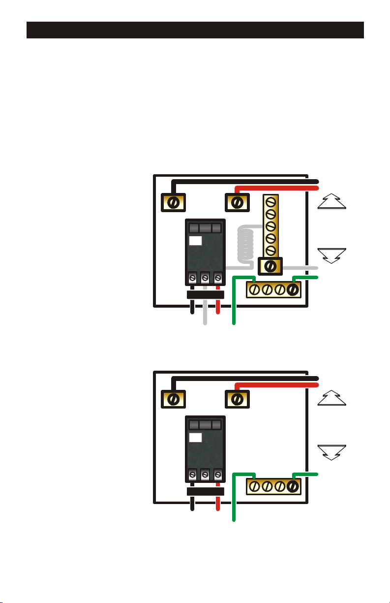
GFCI BREAKER WIRING DETAIL
Improperly wired GFCI breakers are the leading cause of immediate GFCI tripping. It
is important that your system be wired properly, reference the illustrations below for
guidelines.
WARNING: Refer to the circuit breaker manufacturer’s installation instructions. This
illustration is meant to be a guideline, and not meant to override or substitute the
instructions supplied by the breaker manufacturer
LINE 1
LINE 2
GFCI BREAKER #1
(240v 4-wire with neutral)
GFCI BREAKER #2
(240v 3-Wire)
For Independent Heater
LINE LUG #1
LINE LUG #1
LINE LUG #2
TEST
GFCI
(Ground Fault Circuit Interrupter)
CIRCUIT BREAKER
LO A D
LOAD
LOAD
NEUTRAL
GROUND
TO SPA EQUIPMENT
LINE LUG #2
TEST
GFCI
(Ground Fault Circuit Interrupter)
CIRCUIT BREAKER
LO A D
NEUTRAL PIGTAIL
GROUND BUS BAR
GROUND BUS BAR
CONDUCTORS
NEUTRAL BUS BAR
CONDUCTORS
INCOMING
SERVICE
FROM
MAIN
PANEL
NEUTRAL
GROUND
LINE 1
LINE 2
INCOMING
SERVICE
FROM
MAIN
PANEL
GROUND
LOAD LOAD
GROUND
TO SPA EQUIPMENT
9
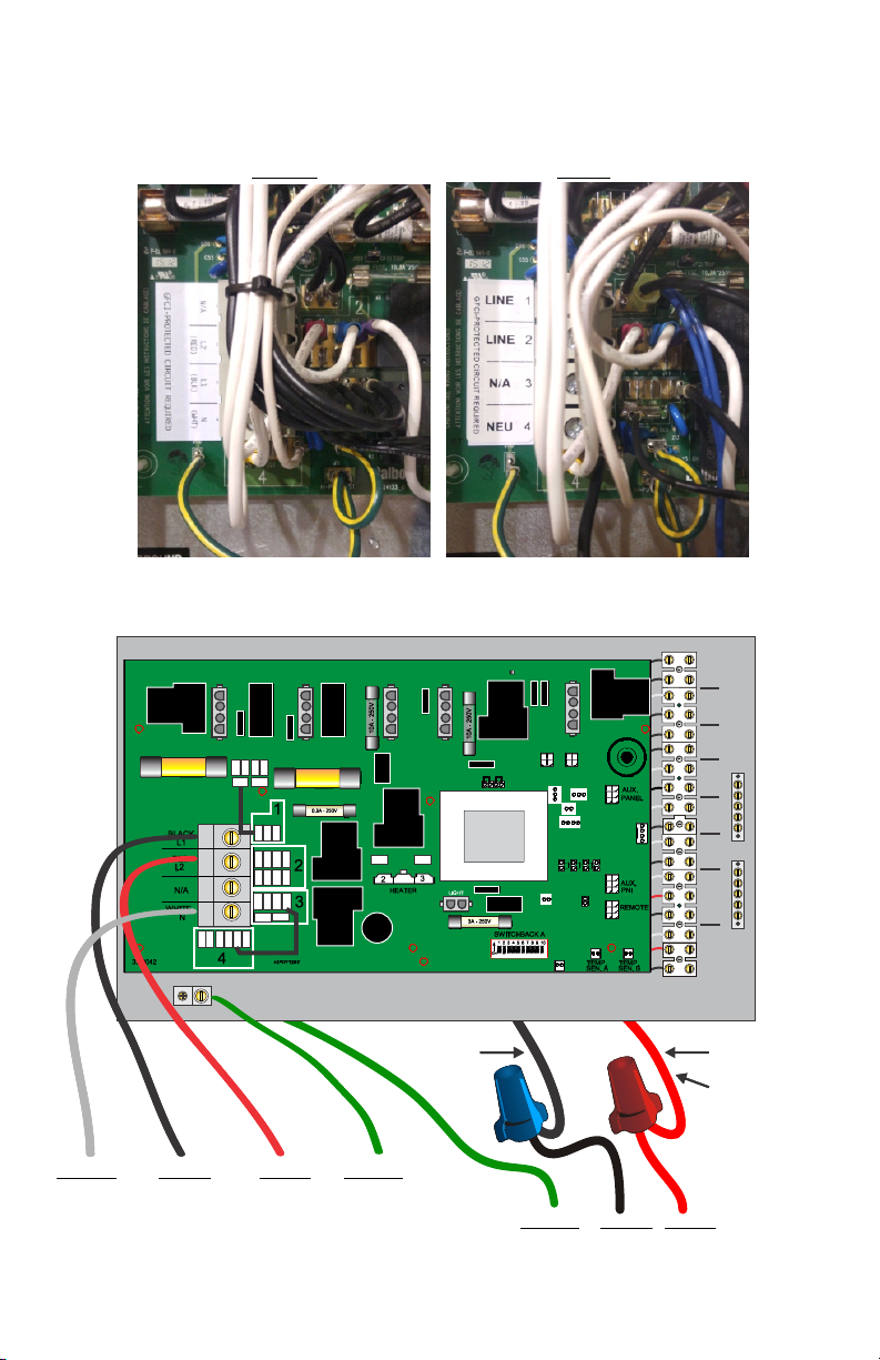
208V ELECTRICAL CONNECTIONS CONSIDERATIONS
IMPORTANT 208V INFORMATION
The system has the capability to operate on 208V provided certain changes are made
to the circuit board transformer and input wiring. When operating on 208V a compatible
pump must be used. A compatible pump would be either 120V or marked specically
for use with 208V.
**240V pumps provided by Hydro-Quip are NOT 208V compatible**
Below is an illustration of the system wiring as shipped from Hydro-Quip. Follow the
instructions on page #X and the illustration on page #X to make the system compatible
with 208V incoming power.
SWITCH
FIREMANS
L L
120V
LIGHT
J35
FUSE 30A
J34
J56
J57
J55
J59
FUSE 30A
J41J60
J51
J52
J98
J72
J42J3J61
J37J4J1
J47
J36
J12
J88
J62
J58J53
J45
J79
J54
J77
J75
J78
J49 J48
MAINMAIN
L C
L C
H L C
H L C L C L L L C
LIGHT
OZONE 12V
GROUNDGROUND
BLOWER
PUMP 3
PUMP 1 PUMP 2
GROUND
Neutral Line 1 Line 2 Ground
GFCI BREAKER #1
(240v 4-Wire only)
see page 8 for breaker sizing
Fig. A
SwtichBank ON:
A2: Add 1 HS Pump with heat
A3: Add 2 HS pumps with heat
A4: Add 4 HS pumps with heat
Move dip switch #2 - #4 to the ON position
to allow high speed pump(s) and heater to
function simultaneously
10
Black
Red
Heater main wires
electric heater models
only
Ground Line 1 Line 2
GFCI BREAKER #2
(240v 3-Wire only)
see page 8 for breaker sizing

Instruction
Wiring Instruction from 220-240v. to 208v. power supply
Ÿ Information provided for Balboa BP-2000 system board only
Ÿ 1 logic jumper P/N 34-20564 is included with this instruction
Ÿ Terminal Block wiring label
Ÿ New diagram# 5195-5197
WARNING! System power must be off when removing or installing logic jumpers
Logic jumper(s) must be programmed to match incoming power supply voltage.
Use these steps if a programming change is required
Step #1 Disconnect power
Step #2 Locate transformer programing bank at position J24 on PCB
Step #3 Conrm system supply voltage with your electrician.
Step #4 Use diagrams below to correctly place logic jumper(s) to match system supply voltage
(Dia #1 = 220-240V. ) (Dia #2 = 208V)
Step #5 Remove and Discard the jumper wire connecting J41 to J12
Step #6 Remove and Discard the jumper wire connecting J51 to J88
Step #7 The wire currently connected to J36 must be relocated to J51
Step #8 The wire currently connected to J52 must be relocated to J75
Step #9 The wire currently connected to J58 must be relocated to J52
Step #10 The wire currently connected to J49 must be relocated to J98
BEFORE AFTER
...connued from previous page
Step #11 New Incoming Power label provided must be applied to circuit board (illustraon below)
Step #12 This instrucon sheet and new diagram must be inserted in the faceplate slip if one is not
currently present
Below is an illustration of the system transformer and wiring converted and ready
for 208V use.
SWITCH
SWITCH
FIREMANS
FIREMANS
L L
L L
120V
120V
LIGHT
LIGHT
J35
J34
J35
FUSE 30A
FUSE 30A
J56
J57
J55
J59
J56
J57
J55
J59
FUSE 30A
FUSE 30A
J41J60
J41J60
J51
J52
J98
J51
J52
J98
J49 J48
J72
J42J3J61
J72
J42J3J61
J37J4J1
J47
J37J4J1
J47
J36
J12
J88
J62
J36
J12
J88
J62
J58J53
J58J53
J45
J45
J79
J54
J77
J75
J78
J79
J54
J77
J75
J78
J49 J48
J34
MAINMAIN
MAINMAIN
L C
L C
L C
L C
H L C
H L C
H L C L C L L L C
H L C L C L L L C
LIGHT
LIGHT
OZONE 12V
OZONE 12V
GROUNDGROUND
GROUNDGROUND
BLOWER
BLOWER
PUMP 3
PUMP 3
PUMP 1 PUMP 2
PUMP 1 PUMP 2
GROUND
GROUND
Neutral Line 1 Line 2 Ground
GFCI BREAKER #1
(208v-240v 4-Wire only)
see page 8 for breaker sizing
10
Black
Ground Line 1 Line 2
GFCI BREAKER #2
(208v-240v 3-Wire only)
see page 8 for breaker sizing
Red
Heater main wires
Heater main wires
electric heater models
electric heater models
only
only
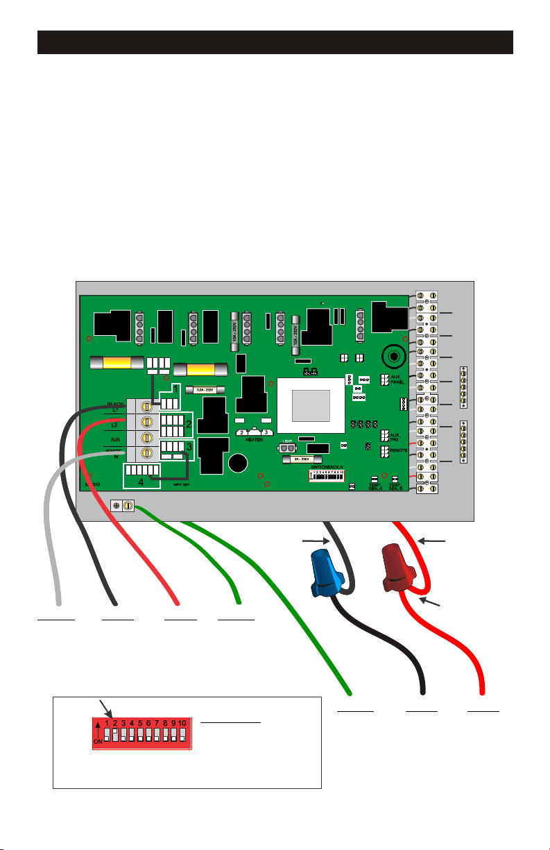
208V ELECTRICAL CONNECTIONS CONSIDERATIONS
Below is an illustration of the system transformer and wiring converted and ready for
Below is an illustration of the system transformer and wiring converted and ready for
208V use.
208V use.
Note wiring changes at the input terminal block and at the voltage conversion jumper(s)
Note wiring changes at the input terminal block and at the voltage conversion jumper(s)
above the transformer.
above the transformer.
SWITCH
SWITCH
FIREMANS
FIREMANS
L L
L L
120V
120V
LIGHT
LIGHT
J35
J34
J35
FUSE 30A
FUSE 30A
J34
MAINMAIN
J56
J57
J55
J59
J56
J57
J55
J59
FUSE 30A
FUSE 30A
J41J60
J41J60
J51
J52
J98
J51
J52
J98
J49 J48
J72
J42J3J61
J72
J42J3J61
J37J4J1
J47
J37J4J1
J47
J36
J12
J88
J62
J36
J12
J88
J62
J58J53
J58J53
J45
J45
J79
J54
J77
J75
J78
J79
J54
J77
J75
J78
J49 J48
MAINMAIN
L C
L C
L C
L C
H L C
H L C
H L C L C L L L C
H L C L C L L L C
LIGHT
LIGHT
OZONE 12V
OZONE 12V
GROUNDGROUND
GROUNDGROUND
BLOWER
BLOWER
PUMP 3
PUMP 3
PUMP 1 PUMP 2
PUMP 1 PUMP 2
GROUND
GROUND
Neutral Line 1 Line 2 Ground
Neutral Line 1 Line 2 Ground
GFCI BREAKER #1
GFCI BREAKER #1
(208v-240v 4-Wire only)
(208v-240v 4-Wire only)
see page 8 for breaker sizing
see page 8 for breaker sizing
Fig. A
SwtichBank ON:
A2: Add 1 HS Pump with heat
A3: Add 2 HS pumps with heat
A4: Add 4 HS pumps with heat
Move dip switch #2 - #4 to the ON position
to allow high speed pump(s) and heater to
function simultaneously
10
Black
Black
Red
Red
Heater main wires
Heater main wires
electric heater models
electric heater models
only
only
Ground Line 1 Line 2
Ground Line 1 Line 2
GFCI BREAKER #2
GFCI BREAKER #2
(208v-240v 3-Wire only)
(208v-240v 3-Wire only)
see page 8 for breaker sizing
see page 8 for breaker sizing
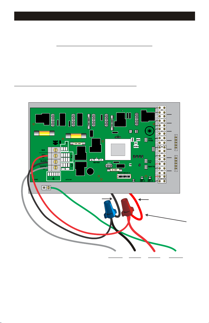
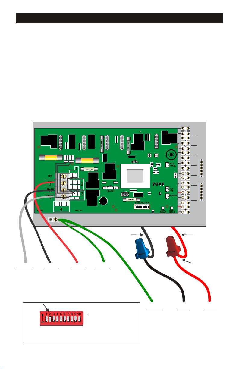
11KW ELECTRICAL CONNECTIONS
11KW electric heat “Main” control system wiring diagram
SINGLE SOURCE WIRE CONNECTION
For correct wire and GFCI breaker sizing, Reference the GFCI breaker sizing matrix
page in this manual
Factory programming will prevent the heater and high speed pump from operating
simultaneously.
FOR SYSTEM MODEL CODES (Label located on outside of box)
ES8848A ES8848B ES8848C CS8800A
ES8850A ES8850B ES8850C
SWITCH
FIREMANS
L L
120V
LIGHT
J35
FUSE 30A
FUSE 30A
J34
MAINMAIN
L C
L C
H L C
LIGHT
OZONE 12V
GROUNDGROUND
BLOWER
PUMP 3
GROUND
Black
Red
HEATER MAIN WIRES
Neutral Line 1 Line 2 Ground
GFCI BREAKER #1
(240v 4-Wire only)
see page 8 for breaker sizing
11
H L C L C L L L C
PUMP 1 PUMP 2
 Loading...