


SpaDepot.com
CS/ES9700Y SERIES
Operation Manual
Covers the following CS & ES series:
9700Y, 9704Y, 9707Y, 9708Y, 9709Y
GECKO
By
Y SERIES
TM

Introduction
This manual covers electrical and installation details on the following
product series. Some photos and instructions may not apply to the
product you have purchased.
-U Series "Fixed" Heater configuration: This series is designed to fit
the most common heater position. Depending upon the actual control
being replaced, you may still need to modify the plumbing to achieve
proper alignment.
-US Series "Slide" Heater configuration: This series is designed to
allow the heater to be positioned within 20" of the control to provide an
installation with a minimum of plumbing modifications. Depending upon
the actual control being replaced, you may still need to modify the
plumbing to achieve proper alignment.
-VH Series "Versi-Heat" Heater configuration: This series is designed
to allow the heater to be positioned within 60" of the control to provide an
installation where there may not be enough room in the immediate
equipment area and to minimize plumbing modifications. Depending
upon the actual control being replaced, you may still need to modify the
plumbing to achieve proper alignment.
-LH Series "Less Heater" configuration: This series allows the use of
customer supplied custom heater configurations which may not have
been available from Hydro-Quip. Please refer to the "LH" wiring diagram
enclosed with the "LH" wiring harness for specific wiring connections and
details NOT covered within this manual.
-LF Series "Lo-Flo” heater configuration: This series allows the use of
Lo-Flo style heater assemblies.

Table of Contents
Important Safety Instructions.............................3-4
Electrical Installation..........................................5-7
GFCI Wiring Detail................................................7
Heater Installation.................................................8
Versi-Heat / Optional Heaters...............................8
Power Connection................................................9
Circuit Board Configurations...............................10
Pump Cord Connections.....................................10
WiFi Module Installation Kit.................................11
Spaside Control Installation................................12
Spaside Functions/Features..........................13-15
Power Up & Breaker Settings.............................16
Changing Low-Level Configuration.....................16
Spaside Messages.........................................17-18
Operation Considerations....................................19
Trouble Shooting............................................20-21
System Data Label..............................................22
Warranty Information...........................................22

IMPORTANT SAFETY INSTRUCTIONS
!
DANGER To reduce the risk of injury, do not permit children to use this product
unless they are closely supervised at all times.
!
WARNING - RISK OF CHILD DROWNING. Extreme caution must be exercised to
prevent unauthorized access by children. To avoid accidents, ensure that children
cannot use a spa or hot tub unless they are supervised at all times.
!
DANGER To reduce the risk of injury to persons, do not remove suction fittings.
Spa location must accommodate sufficient drainage of water around the base of the
structure, as well as the power source compartment.
Prolonged immersion in water that is warmer than normal body temperature can result
in a dangerous condition known as HYPERTHERMIA. The causes, symptoms,
and effects of hyperthermia may be described as follows: Hyperthermia occurs
when the internal temperature of the body reaches a level several degrees above
the normal body temperature of 98.6BF. The symptoms of hyperthermia include
dizziness, fainting, drowsiness, lethargy, and an increase in the internal
temperature of the body. The effects of hyperthermia include (1) unawareness of
impending hazard, (2) failure to perceive heat, (3) failure to recognize the need to
exit spa, (4) physical inability to exit spa, (5) fetal damage in pregnant women, (6)
unconsciousness resulting in danger of drowning. WARNING The use of alcohol,
drugs or medication can greatly increase the risk of fatal hyperthermia in hot tubs
and spas.
!
DANGER - RISK OF ELECTRICAL SHOCK.
A spa may be installed within 5 feet of metal surfaces if each
permanently connected by a solid copper conductor attached to the wire connector
on the terminal box . Refer to NEC and local codes
installation.)
A bonding lug is provided on the control box to permit connection of a
solid copper bonding conductor between this point and any equipment, metal
enclosures of electrical equipment, metal water pipe, or conduit within 5 feet
(1.5m) of the unit as needed to comply with local requirements.
Bond accessible metal to the dedicated connector on the equipment grounding bus,
bond the equipment ground bus to the local common bonding grid as part of the
installation in the form of (1) a reinforced concrete slab for support, (2) a ground
plate provided beneath the hot tub or spa, or (3) a permanent ground connection
that is acceptable to the local inspection authority.
!
DANGER RISK OF ELECTRICAL SHOCK. Do not permit any electrical appliance,
such as a light, telephone, radio, or television, within 5 feet (1.5m) of a spa or hot
tub.
To reduce the risk of injury:
The water in a spa or hot tub should never exceed 104BF (40BC). Water temperatures
between 100BF (38BC) and 104BF (40BC) are considered safe for a healthy adult.
Lower water temperatures are recommended for extended use (exceeding 10-15
minutes) and for young children.
Excessive water temperatures have a high potential for causing fetal damage during
the early months of pregnancy, pregnant or possibly pregnant women should limit
spa or hot tub water temperatures to 100BF(38BC).
Before entering the spa or hot tub, the user should measure the water temperature
with an accurate thermometer.
The use of alcohol, drugs, or medication before or during spa or hot tub use may lead
to unconsciousness with the possibility of drowning.
Persons suffering from obesity or with a medical history of heart disease, low or high
blood pressure, circulatory system problems, or diabetes should consult a
physician before using a spa or hot tub.
in effect at the time of
metal surface is
3

IMPORTANT SAFETY INSTRUCTIONS
Persons using medication should consult a physician before using a spa or hot tub
since some medication may affect heart rate, blood pressure, and circulation.
For Cord and Plug Connected Units
Must be connected to a grounded, grounding type receptacle only. NEVER connect
the spa to an extension cord.
Do not bury the cord.
For Permanently Installed Units
A terminal marked “G” or “ground” is provided in the wiring box located inside the
equipment compartment. To reduce the risk of electric shock, connect the
terminal or connector to the grounding terminal of your electrical service or supply
panel with a continuous green insulated copper wire in accordance with National
Electric Code Table 250-95 and any other local codes in effect at the time of the
installation.
For Permanently Installed Units not Provided with an Internal Disconnecting Method
The electrical supply for this product must include a suitably rated switch or circuit
breaker to open all ungrounded supply conductors to comply with Section 422-30
of the National Electric Code, ANSI/NFPA 70 1987. The disconnecting means
must be readily accessible to the tub occupant but installed at least 5 feet (1.5m)
from the tub water.
For Units with Gas Heaters
WARNING - Do not install indoors. This unit uses a gas heater that requires proper
ventilation and is intended for outdoor use only.
High Voltage Warning
HIGH VOLTAGE CAN SERIOUSLY INJURE OR KILL!
ONLY EXPERIENCED TECHNICIANS SHOULD SERVICE THIS EQUIPMENT.
DO NOT remove the protective covers from any electrical enclosure, or
attempt to service any related electrical device, unless you are a qualified
electrician or service professional.
DANGER
Risk of electric shock. Before working with any electrical connections,
make certain that the Main Power breaker from the house breaker box has
been turned off.
WARNING
All electrical work must be performed by a qualified electrician and must
conform to all local codes.
IMPORTANT
Due to the danger of severe electrical shock, locate all power disconnects
before servicing a spa. Precautions must be taken whenever working with
breaker boxes, G.F.C.I.’s, or service disconnects.
4
Electrical Installation
A licensed electrician must accomplish the electrical installation in accordance with
the National Electric Code(NEC) Article 680, and any local codes in effect at the
time of installation.
Refer to the System Data Label for equipment voltage and maximum amperage
draws.
The GFCI (Ground Fault Circuit Interrupter) is a mandatory electrical safety device
required for all portable spas and hot tubs as specified in the National Electrical
Code Article 680-42. The GFCI in your particular installation may be installed at the
electrical service panel or a separate sub-panel.
Use copper conductors ONLY. The ground must be sized following the National
Electric Code, Table 250-122. For Power conductor size, refer to the National
Electric Code Table 310-16.
A bonding lug has been provided on the control box to allow connection to local
ground points. To reduce the risk of electrical shock, a solid copper bonding wire
should be connected from this lug to any metal objects within 5 feet of the spa.
The NEC and most local codes require that a “disconnect” be installed within
“line-of-site” of the spa.
Circuit & Breaker
Rating
Maximum Amps
Minimum Wire
Size
The above table is a wiring chart representation.
IMPORTANT- If your electrician is not absolutely sure how to connect
your system correctly, call your local dealer. Any mistake may be costly
and void your equipment warranty.
CAUTION: Do not connect or disconnect any components while the power is on.
All connections must be done with the power off as it may cause damage to the
system.
**Any resulting damages are not covered under manufacturer’s warranty**
CAUTION: Damage may occur to the circuit board and spaside if the spaside
plug is not properly aligned to the receptacle on the circuit board or if the
spaside plug is connected or disconnected while the power is on.
**Any resulting damages are not covered under manufacturer’s warranty**
15A 20A 30A 40A 50A 60A
12A
16A 24A
14 12 10
32A 40A 48A
8
6 4
5
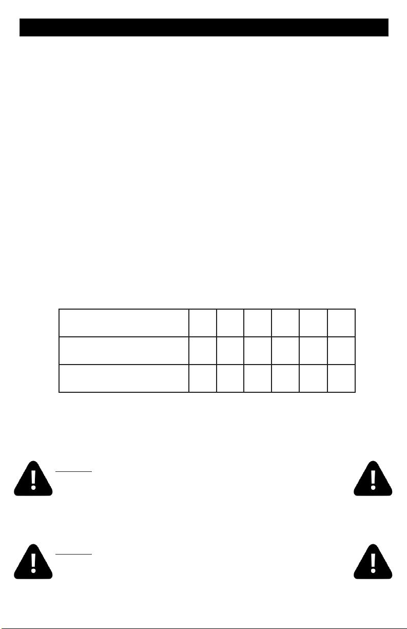
Electrical Installation
ELECTRICAL CONNECTIONS
OPTION 1
20-60AMP HARDWIRED
MAIN BREAKER PANEL
LINE 1
N
LINE 2
Option 1 shows the power from GFCI breaker installed into main service panel to a
service disconnect within line-of-site of the spa. If the manufacturer of your homes main
breaker panel makes a GFCI breaker, you may be able to add it to an open slot in the
panel.
GFCI Installed in Main Service Panel
INLINE SPA DISCONNECT
PORTABLE SPA
REFER TO GFCI WIRING DETAIL ON PAGE 8
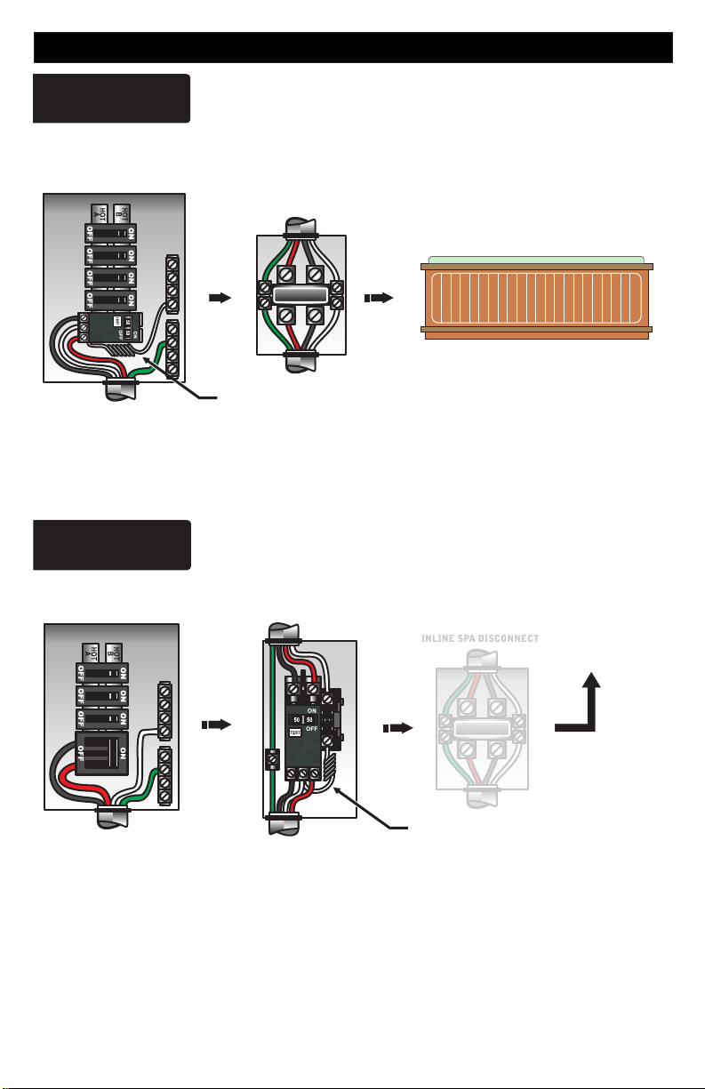
OPTION 2
20-60AMP HARDWIRED
MAIN BREAKER PANEL
Subpanel GFCI Installed
GFCI DISCONNECT
INLINE SPA DISCONNECT
TO PORTABLE SPA
LINE 1NLINE 2
REFER TO GFCI WIRING DETAIL ON PAGE 8
Option 2 shows the power from main service panel to a GFCI subpanel within line-of-site
of the spa. (Note: Most local codes will allow a GFCI subpanel to be a disconnect. If this is
not the case in your installation, a disconnect must be provided.)
6
Electrical Installation
If your system was configured to include a 120VAC power cord, ensure that the proper
receptacle has been installed (a dedicated circuit is required). DO NOT under any
circumstances modify a 20 Amp plug to fit into a 15 Amp receptacle or use an extension
cord. Doing so will create hazardous conditions and/or invalidate the warranty.
OPTION 3
15/20AMP CORD END GFCI
MAIN BREAKER PANEL
Units with 15A / 20A GFCI Plug Connection
DEDICATED
15A / 120V OUTLET
PORTABLE SPA
This illustration depicts a typical 15 AMP, cord-end GFCI installation.
(The spa must be installed on a dedicated circuit.)
GFCI Wiring Detail
It is important that the GFCI circuit breaker is installed correctly. Often this
component has been improperly installed causing the breaker to instantly trip
when the system is turned on. Below is an illustration of a typical GFCI breaker
installation.
WARNING: Refer to the circuit breaker manufacturers installation
instructions. This illustration is meant to be a guide for Field Technicians
and is not intended to override or substitute the instructions supplied with
the circuit breaker.
LINE 1
LINE 2
LINE LUG #1
TEST
GFCI
(Ground Fault Circuit Interrupter)
CIRCUIT BREAKER
LOAD
LINE 1
NEUTRAL
TO SPA CONTROL SYSTEM
LINE LUG #2
LINE 2
GROUND
INCOMING
SERVICE
CONDUCTORS
FROM
MAIN
NEUTRAL PIGTAIL
GROUND BUS BAR
NEUTRAL BUS BAR
LOAD NEUTRAL MUST BE CONNECTED
DIRECTLY TO GFCI AS SHOWN
PANEL
NEUTRAL
GROUND
7

Heater Installation
The "U" Series Fixed Heater and "US" Series Slide Heater systems will arrive from the factory with the
heater mounted in the bottom location as pictured in Step 1. The "US" Series Slide Heater can be used in
this configuration or you can move the Slide Heater to the back of the control as shown below to align
easily with your particular plumbing arrangement.
Slide heaters are using the Gecko in.flo technology so it may be installed on either the
pressure or vacuum side of the pump.
Step 1
Remove the control system from the carton and
verify contents for completeness. If the
application is a bottom mount installation then
you are ready to go directly to step 6.
Step 3
Adjustable
Clamp
Adjustable
Clamp
When the adjustable clamps are mounted to the
heater, adjust the stud locations to align with the
slide brackets on one end. Do not tighten nuts
yet.
Step 5 Step 6
Step 2
EZ-Access
Heater Retainer
If you n eed to r elocate the heate r for your
installation, simply remove the EZ-Access Heater
Retainers and remove the heater from under the
box. To utilize the slide brackets, install adjustable
stud clamps that are provided in the installation kit to
the heater assembly.
Step 4
Align the other studded clamp and attach to the
other slide bracket. Now determine the proper
alignment for the heater and tighten the nuts and
clamps
Adjustable
Clamp
Ground/Bond the heater directly to the control
box using #8 solid bonding wire. (not included)
Connect the power control cords from the heater
to the matching receptacles on the control box.
Versi-Heat / Optional Heaters
The Versi-Heat series heaters are supplied with a 60” cord which allows for versatile installations and
locations. BE SURE HEATER IS INSTALLED HORIZONTALLY.
Versi-Heat heaters are pressure switch controlled. They must be installed on the
pressure side of the pump.
IMPORTANT - Heater pump must provide a minimum flow of 18 GPM through the heater.
8

Power Connection
IMPORTANT: Always refer to the product data label (located on top of the
control box) for specific electrical information.
Ÿ Use copper conductors only as required by the NEC.
Ÿ Secure wires as defined by the NEC and in compliance with any local
codes in effect at the time of installation.
240-VOLT ELECTRICAL SERVICE REQUIREMENTS
P9 (240V)
INPUT
VOLTAGE
240V
RED
WHITE
BLACK
L2
N
L2
L1
4
3
N
2
1
L1
GREEN
GR
Heater Voltage (P12) Brown Wire:
Moves to P9 for 240V (Default)
120-VOLT ELECTRICAL SERVICE REQUIREMENTS
INPUT
VOLTAGE
120V
---
WHITE
BLACK
GREEN
N
L1
---
L1
4
3
N
2
1
GR
P5 P7
P79
P2
P5 P7
P79
P2
P9
P10
P14
P15
F1
P11
P13
P6
P78
P12
P12
P10 (120V)
P9
P10
P14
P15
F1
P11
P13
P6
P78
P12
P25
FUSE 30A
P18
P19
P25
FUSE 30A
P18
P19
P17
P17
P21
P21
Heater Voltage* (P12) Brown Wire:
Moves to P10 for 120V
*Heater wattage is rated at 240V. When running 120V to heater, output is approximately 25%.
IMPORTANT- All equipment must be rated for 120VAC.
9

Circuit Board Configurations
Component Volts Amps Wire End Color Code From To
P1 2-SPD 240V 12A Red
N L2
Pump 2 240V 12A Violet / Blue
N L2
Pump 3 240V 10A Violet
N L2
Blower 240V 8A Violet
N L2
Ozone 240V 1A Yellow
N L2
Circ Pump 240V 2A Blue
N L2
All component outputs are pre-configured for 120V. If 240V output is required, please
utilize the illustration below and the wiring diagram that was included with your unit for
the correct component location to properly convert to 240V.
Neutral & L2
Sections
K2
K4
K6
G N
P47
P48P49P50P51P52
P53
P56
P57
P58
P59
P60
P61
P62
P55
L2
P67P68P69P70P71P72
P73
P77
120V
Neutral Section
N
240V
L2 Section
L2
Voltage Selection Chart for 240V Conversion
2-SPEED PUMP CORD CONFIGURATION
The following wiring configuration is for two-speed pump circuits.
System
Pump Cord Connections
Black = High Speed
Red = Low Speed
White = Common
Green = Ground
SINGLE SPEED PUMP / ACCESSORY CORD CONFIGURATION
The following wiring configuration is for single-speed pump circuits, circulation
pumps, ozones, blowers and accessories.
Black = Hot/Line
System
White = Common
Green = Ground
Pump
Single Speed
Device / Acc
10

Wi-Fi Module Installation Kit (Optional)
Your new system has the capability to connect with the internet by using a Wi-Fi
Module Kit (sold separately).
If using this option with your system, please make sure to install the module kit
following these few steps:
Step 1 - Insert the wi-fi module cable connector (MODULE “CO”) into the empty
connection on the system circuit board marked “CO” (Fig.1)
Step 2 - Connect the other module (MODULE “EN”) directly to a wi-fi router
utilizing the included network cable and power adapter. (Fig.2)
Wi-Fi Module Kit
PT# 34-0216G
INTERNET
Fig.1
K6
P45
CO Port (Wi-Fi)
P46
P55
P77
CO C1CO
MODULE “CO” MODULE “EN”
Status
Indicator
Fig.2
WI-FI ROUTER
NETWORK CABLE
Circuit Board
Step 3 - Please follow the detailed instructions provided with the wi-fi module kit
to properly install your Gecko (in.Touch 2) App and control the spa.
Note: If you experience poor connection performance it may be necessary to
relocate the modules closer together.
Status Light Indicator
Spa Transmitter (CO)
Pairing mode Yellow (Blinking)
Spa controller not detected Red
in.touch 2 server detected
Module is fully functional
Blue
Home Transmitter (EN)
Pairing mode Yellow (Blinking)
Router not detected Red
Router detected Green
in.touch 2 server detected
Module is fully functional
* When the LED status is blinking (blue, green or red) this
indicates communication between the modules has not
been established
Blue
11

Spaside Control Installation
A optional placard has been provided with each control to eliminate problems
encountered when the spaside access hole is too large. Use the illustrations and
instructions below to install the spaside control provided with your system.
TAB LOCK
ADHESIVE
GASKET
IN IN
EXISTING HOLE
Step 1 - (If control cutout already exists,
determine if placard must be used. If existing
cutout is sufficient, disregard step 1.) Choose
a location for the spaside control. Using the
template provided, cut out a 2 5/8” X 6 3/8”
hole. Clean area and insert spaside control
making sure tab locks are rotated inward. (If
placard is required, position and secure using
the provided adhesive gasket.)
Step 3 - Remove protective film from display
window then clean the face of the spaside.
Now carefully align and apply the label. (Fig.3)
Overlay may vary
Fig. 3
PLACARD
OUT OUT
Step 2 - Rotate lock tab screws on face of
control clockwise to engage locks and secure
control into place.
Step 4 - Connect spaside to PCB
connection marked C1. (Fig.4)
K6
P45
MAIN KEYPAD
P46
P55
P77
CO C1CO
Fig. 4
12

Power
CS970XY Spaside Functions / Features
Pump 1 Pump 2 Blower Light
Program Temp Up Temp Dwn
Pump 1 - Press o nce to turn
Pump 1
Indicator
on low speed. Press a second time to turn pump to high
Pump 2
Indicator
Blower
Indicator
Filtration
Light
Indicator
Indicator
Heater
Indicator
speed
(with a dual-speed pump). A third time turns pump off.
A built-in timer automatically turns the pump off after 20 minutes unless manually deactivated
first.
The “Pump 1” indicator lights
up when Pump 1 is on. With
will fl ash when Pump 1 is on at
low speed.
dual-speed pump, indicator
Pump2 - Press once to turn on pump on, press a second will turn the pump off unless
Two speed pump. Two speed pump functions as Low, High, Off
A built-in timer automatically turns the accessory off after 20 minutes unless manually deactivated
first.
The “Pump 2” indicator lights
ey
Blower k
-
Press Blower key to turn blower on. Press Blower Key again
up when Pump 2
is on.
to turn
off.
A built-in timer automatically turns the accessory off after 20 minutes unless manually deactivated
first.
blower
The “
Light -
” indicator lights up
when Blower is on.
Press once to turn light on. Press Light key a second time to
turn light off.
A built-in timer automatically turns the light off after 2 hours unless manually deactivated first.
The “Light” indicator lights up
when light is on.
Temp Up - Use Up key to raise the temperature Set Point. The temperature setting will
be displayed for 5 seconds to confirm your new selection.
The "Set Point" icon indicates that the display shows the
desired temperature,
NOT the current water temperature!
Temp Down - Use Up key to lower the temperature Set Point. The temperature setting
will be displayed for 5 seconds to confirm your new selection.
The "Set Point" icon indicates that the display shows the
desired temperature,
NOT the current water temperature!
13

Spaside Functions / Features (Cont.)
Power Key - This key provides access to:
Manual Economy Mode - When active this mode forces the system to maintain a
temperature 20F° less than the set temperature. The display will toggle between “E ”
the clock and the water temperature. Press the power button again to disable economy
mode.
E = Economy mode active
E = Economy mode not active
FILTER/PROGRAM Key: A quick press of the Filter key will allow you to display the
clock. A long press of 5 seconds will allow you to enter the program menu. In the
program menu, the following parameters can be set: the clock, the filter cycles or the
purge cycles, the economy mode and the temperature units. While you are in the
program menu, use the up or down keys to adjust the parameters and use the Filter key
jump to the next parameter.
Note: Changes will be saved after the confirmation of the last parameter only. If
there is no key press for 10 seconds, the system will exit the program menu
without saving the changes.
Setting the Clock: Enter the programming menu by pressing and
holding the FILTER key for 5 seconds. The current time will be
displayed with the hours flashing.
Press the UP or DOWN key to adjust the hours accordingly making
sure the PM indicator is set properly.
* PM indicator
Press the PROGRAM key to advance to changing the minutes
Press the UP or DOWN key to adjust the hours accordingly making
sure the PM indicator is set properly.
Setting the Filter Cycle: Enter the programming menu by pressing
and holding the FILTER key for 5 seconds. The current time will be
displayed with the hours flashing. If adjusting the clock is necessary
do it now, otherwise press the FILTER key repeatedly until FS## is
displayed. “FS” represents FILTER START “##” represents the
start time hour.
Press the UP or DOWN key to adjust the hours accordingly making
sure the PM indicator is set properly.
Press the FILTER key until F ## is displayed. “F ” represents
FILTER DURATION “##” represents the run time for the filter cycle
in hours.
0 = No Filtration
24 = Continuous Filtration
P
P
14

Spaside Functions / Features (Cont.)
Setting the Filter Cycle Frequency: - Enter the programming menu
by pressing and holding the FILTER key for 5 seconds. The current
time will be displayed with the hours flashing. If adjusting the clock is
necessary do it now, otherwise press the FILTER key repeatedly until
FF## is displayed. “FF” represents FILTER FREQUENCY “##”
represents the number of cycles per day, 1 - 4 cycles per day.
Press the UP or DOWN key to adjust the cycles as required.
Setting the Economy Mode: Enter the programming menu by
pressing and holding the FILTER key for 5 seconds. The current time
will be displayed with the hours flashing. If adjusting the clock is
necessary do it now, otherwise press the FILTER key repeatedly until
EP## is displayed. “EP” represents ECONOMY PROGRAM
“##” represents cycle enabled or not
1 = On / Cycle Enabled
0 = OFF / Cycle Disabled
Press the UP or DOWN key to adjust the setting as required.
Setting the Economy Start Time: Enter the programming menu by
pressing and holding the FILTER key for 5 seconds. The current time
will be displayed with the hours flashing. If adjusting the clock is
necessary do it now, otherwise press the FILTER key repeatedly until
ES## is displayed. “ES” represents ECONOMY START, “##”
represents hour the cycle starts
Press the UP or DOWN key to adjust the setting as required paying
close PM indicator.
Setting the Economy Duration: Enter the programming menu by
pressing and holding the FILTER key for 5 seconds. The current time
will be displayed with the hours flashing. If adjusting the clock is
necessary do it now, otherwise press the FILTER key repeatedly until
PP
e ## is displayed. “e ” represents ECONOMY DURATION,
“##” represents the active time in hours.
Press the UP or DOWN key to adjust the hours as required
0 = No Economy
24 = Continuous Economy
Changing the Temperature Readout: Enter the programming menu
by pressing and holding the FILTER key for 5 seconds. The current
time will be displayed with the hours flashing. If adjusting the clock is
necessary do it now, otherwise press the FILTER key repeatedly until
F or C is displayed.
Press the UP or DOWN key to adjust as required
F = Farenheit
C = Celcius
15

Power Up & Breaker Setting
Power-up & breaker setting
Boot up display sequence (Each parameter is displayed for 2 seconds)
8.8.8
Lamp test
All the segments and
LEDs light up.
260
Software number
Software Part Number Revision of the Software
2
Software Revision
Low-level selection
Low-level selected
from Low-level menu
It’s important to specify the current rating of the GFCI used to ensure safe and efficient
current management (and reduce nuisance GFCI trippings).
98
Thevalues displayed by the system
correspond
amperage capacity of
Use
desired value.
modified typically from10to 48
AMP.
to 0.8 of the maximum
Down button to select the
Up /
the GFCI.
The valuecan be
safe
the
and
It'simportant to specify
current rating of the GFCI
usedto ensure
efficient
(and reduce nuisanceGFCI
trippings)
Press and hold Filter button
until you access the breaker
setting menu.
NOTE: If all installed components do not operate or only one
component can be operated at a time it may be caused by this
setting. Set breaker size accordingly to allow components to run.
current management
.
Changing System Low-Level Program Configuration
Although every system has been factory set, in certain cases when servicing or replacing a
unit in the field, it may be necessary to set a new pre-determined low-level program
configuration. Follow these simple steps to re-enter the low-level programming using the
spaside control.
Then press Filter button to set breaker
rating. This table shows typicalsettings
for different
of b
one that matches your breaker.
GFCI b
60 Amp 48 Amp
50 Amp 40 Amp
40Amp 32Amp
30Amp 24
20Amp
GFCI ratings. Select the
Amp
Amp
16
98
Pressand hold the Pump 1
key for 30 seconds
The spaside display will show L xx
configuration number
Use the
Temp Up/Down
number and press the
the configuration selectionchart below).
If the Filter key is not pressed within 25 seconds, the unit will exit this menu
without changing any settings.
registered in the system.
keytochoose the new desired
Filter key to confirm the selectedconfiguration (referto
where "xx" representsthe previous
low-level configuration
Low-Level Configuration Number Chart
If at power-up of the system and spaside display shows the following message: , it
means that all low-level configurations have been downloaded, but no configuration
number has been chosen.
L __
16

Smart Winter Mode
Smart Winter Mode (SWM) protects the spa and equipment by monitoring the
temperature within the equipment bay. When a freezing condition is detected SWM
becomes active for the next 24 hours. During this period the system will start the Pump(s)
and Blower for a minimum of 1 minute at preset intervals becoming more frequent the more
severe the freezing condition becomes.
The Filtration Icon “Blinks” when
“Smart Winter Mode” is active
Spaside Messages
An internal hardware error has been detected in the spapack
Temperature sensor malfunction
This error will occur when a problem with the temperature sensor exists.
Contact your local spa dealer
Water has exceeded 108F at the temperature sensor.
The heater, pump and accessory will be deactivated until the water
cools. Be sure to check the actual water temperature with an accurate
thermometer.
DO NOT ENTER SPA WATER!!
The spa water has exceeded 119F at the high-limit sensor.
The heater will deactivate while the pump and accessory will still
operate. The blower (if equipped) can be activated to help cool the
water. Water must be below 119F and power must be reset to clear the
“HL” error
DO NOT ENTER SPA WATER!!
1. A dirty spa filter can also cause a restricted flow of water, be sure the
filter is cleaned regularly and ensure all water shutoff valves are open.
2. If the system has been operating normally until now, the pump may
be overheating the spa. Refer to “Programing Filtration” on page 18 and
reduce the duration and/or number of cycles per day.
3. If you’ve eliminated items 1 & 2 as problems, the high-limit sensor
may have malfunctioned.
Contact your local spa dealer
The system did not detect any water flow while the heater pump was
running.
Make sure that the low-level programming has been properly set, with
or without circulation pump (depending on your system configuration)
Make sure water valves are open and proper water level
Check and remove anything obstructing the filter
17

Spaside Messages Cont’d
The system detected water flow when the heater main pump was
or is off.
Make sure that the low-level programming has been properly set, with
or without circulation pump (depending on your system configuration)
If present while heater pump is off pressure/flow switch may be stuck
shut or need replacement and/or adjustment.
Ground
RED:
Pump 1 / 2-Speed
PINK:
Pump 2 or 3 / 1-Speed
Ground
Brown:
Pump 2 / 2-Speed
No low-level
configuration software
has been downloaded
intothe system.
Temperature inside the spa skirt istoo high, causing the
internal temperature in the spa pack to go above normal
limits .
System Plug Pinouts
High Speed / Black
Low Speed / Red
Common / White
Hot / Black
Ground
Common / White
Low Speed / Red
High Speed / Black
Common / White
PURPLE:
Air Blower / 1-Speed
YELLOW:
Ozone
BLUE:
Circ. Pump
Note flat sides in connector
Low Speed / Red
High Speed / Black
Common / White
Ground / Green
Ground
Hot / Black
Common / White
Common / White
Ground
Hot / Black
Ground
Hot / Black
Common / White
Testing / Replacing the Sensor Set
18

Operation Considerations
The following describes situations you may encounter and situations to be
aware of.
Warm Weather Conditions
Since your spa will normally be expected to maintain warm to hot water ready for use, a great deal of
attention has been directed to the energy conservation detail of insulation to keep electrical cost down.
Energy conservation efficiency may be achieved by extensive insulation of the spa cabinet, plumbing,
spa shell and in some climates full foam insulation may have been provided. This energy conservation
feature may cause an inconvenience during warmer times of the year. During warm periods of the year,
the temperature within the equipment compartment can elevate to a point that the pump will automatically
turn off for a short amount of time (15-30 minutes) to allow the pump to cool down before automatically
restarting. This cool down feature will not harm your spa, but serves only to protect the pump from
damage ad as and indicator that it is too hot. To minimize this occurrence, refrain from using your
Hydrotherapy Jets for prolonged periods of time during warm seasons. The jet pump chosen for your spa
has been specifically sized for maximum performance and your Hydrotherapy enjoyment.
Filtration System
Please refer to your Spa Manufactures Owner’s Manual regarding the operation, maintenance and
cleaning of your filtration system.
IMPORTANT - Heater pump must provide a minimum flow of 23 GPM through heater.
Winterizing
When freezing weather and/or power losses are expected, contact your local spa dealer for freeze
protection or winterizing recommendations for both the spa and the equipment system. Freeze
related damage is not covered by the warranty.
Chemical Water Treatment
Your dealer is familiar with local water conditions and which chemicals are compatible with and designed
specifically for your spa. This is the best person to advise you on proper water quality management. The
one thing you can do to insure years of trouble free equipment operations is to maintain proper water
chemistry.
Two basic goals of the chemical water treatment are sanitizing and balancing the water. Sanitizing simply
means keeping the water free from microorganisms including algae, bacteria and viruses. The current
most popular chemicals for sanitizing include chlorine, bromine and ozone.
Balancing water means establishing a balance among pH, total alkalinity and total hardness. Water that is
unbalanced can corrode the spa and it’s support equipment or leave deposits of minerals. Properly
balanced water is essential to allow the sanitizing chemical to work effectively. There are numerous
chemical additives to help you in controlling pH, total hardness and alkalinity. Never use softened water
when filling you spa. Softened water is extremely corrosive to the metal parts of the spa equipment and
may lead to an unforeseen failure. Sometimes, despite your most diligent efforts, your water may become
to far out of balance to be managed chemically. At this point it is probably better to drain and clean the spa
and start over with fresh water. Equipment failure caused be improper water chemistry will not be covered
under warranty. Saltwater purification systems can potentially damage your equipment. Any related
failures will not be covered under warranty.
19

Troubleshooting
The following describes situations and possible solutions to common problems you may
encounter as a spa owner.
Nothing Operates
Main Breaker is OFF - Set to On.
Sub-Panel Breaker Off - Set to On.
Equipment GFCI Off - Set to On.
Power switch in Off position - Set to On.
Components not plugged in - Plug in components.
Power cord not plugged in - Plug in power cord.
Over or High Temperature Protection On - Refer to Spa Side Messages.
No, Low or Surging Water Flow
Air Lock in Plumbing System - “Bleed” the system.
Restricted Flow - Insure that the water shut-off valves are open and that suction
fittings are not blocked by debris.
Dirty Filter - Clean or replace filter.
Low Water Level - Increase water level to recommended level.
Low Speed Pump Not Operational
Circuit board configuration is Incorrect - Contact your local dealer.
Pump Not Plugged-In - Plug in the Pump.
Blown Fuse - Contact your local dealer.
Jets or Blower Not Operational
Blower or Pump Not Plugged-In - Plug in the Blower or Pump.
Blown Fuse - Contact your local dealer.
Over or High Temperature Protection On - Refer to Spa Side Messages.
TroubleShooting
20

Troubleshooting
Therapy Jet Not Operational
Water Shut-Off Valves are Closed - Open Shut-Off valves.
Dirty Filter - Clean or replace filter.
Jets Not Properly Adjusted - Adjust Jets properly.
Diverter Valve Not Properly Adjusted - Adjust diverter valve properly.
Thermal Overload Tripping - Check for restricted flow of water.
Water Leaks
Spa Overfilled - Adjust water level.
Too Many People in the Spa - Adjust water level.
Drain-Valve Left Open - Close drain valve.
Couplings or Unions Loose - Tighten or contact your local dealer.
Pump Seal Leaking - Contact your local dealer.
Plumbing / Connections Leaking - Contact your local dealer.
Water Leaking from Spaside Control - Contact your local dealer.
Water in Air Blower Plumbing - Contact your local dealer.
No Heat
Temperature Not Set Correctly - Adjust Set Point.
Over or High Temperature Protection On - Refer to Spa Side Messages
Current Limiting On - 120V Systems will not heat if High Speed or Blower is on.
Contact your local dealer.
No Power - Reset breaker at service panel.
Low Water Flow - Clean or Replace filter.
System is in Rest Mode - Refer to Modes on page 19.
Light Not Operation
Light Bulb Defective - Replace bulb or contact your local dealer.
Reflector has Fallen Off - Replace deflector or contact your local dealer.
Light Not Plugged-In - Plug in the Light.
High Heat
Filter Cycles Running Too Long - Adjust filter cycles down.
Temperature Set Too High - Adjust Set Point.
High Ambient Temperature - Remove spa cover.
GFCI Breaker Trips Occasionally
Lightning / Electrical Storm or Power Surge
NOTE: The GFCI breaker must be properly installed by a licensed electrician.
GFCI Breaker Trips Immediately
Defective Component or Improper GFCI Breaker Installation - Contact a qualified
service technician or the factory for assistance.
Temp/Hi-Limit sensor not connected - Connect Temp/Hi-Limit to P38 on PCB
- Reset GFCI Breaker.
21

System Data Label
Note: This information will be necessary if you should ever have to request warranty or
any other type of service.
The system data label is located on the control box. This label is very important and
contains information you will need to establish your electrical service. The voltage and
amperage ratings are shown on the bottom of the label. Product, Model, Serial and Code
numbers are also shown on the label.
Corona, CA 92880 | www.hydroquip.com
SAMPLE
E99812
Warranty Information
Hydro-Quip warrants its products to the original purchaser to be free from defects in
material and workmanship for a period of 1 year (12 months) from the original date of
purchase, except as noted below.
Products which become defective within the warranty period will be repaired or replaced (at
the option of Hydro-Quip) except for damage due to freezing, water chemistry, negligence,
abuse, misuse, misapplication, unauthorized modification, improper installation, normal wear
and tear or chemical attack.
This warranty extends only to normal, personal (non-commercial) usage by the original
purchaser. Pump seals, o-rings, gaskets, air blower brushes are only covered for 90 days
from original date of purchase.
Hydro-Quip will not be responsible for labor incurred in removing, inspecting or reinstalling of
warrantable products. Hydro-Quip will not be responsible for any travel related charges or
labor costs attributable to disassembly and reassembly of the spa, skirt, decking or any other
materials enclosing the product, or attributable to difficulties in gaining access to the product.
Hydro-Quip will not be responsible for labor incurred for routine maintenance, adjustments or
alterations to the calibration of electrical devices.
Any products which are claimed to be defective must be shipped freight prepaid to HydroQuip and the repaired or replaced product will be returned to the sender freight collect. When
sent to Hydro-Quip, the product must be accompanied by the sales receipt or other proof of
the purchase date as well as the sender's name, mailing address, daytime phone number and
a detailed description of the defect as well as any other information relating to this claim.
Unless state law expressly provides otherwise, Hydro-Quip will only be responsible for repair
or replacement of any of its products that are found to be defective as provided above, and will
not bear the cost of any consequential damages. This warranty gives you specific legal rights
but you may have other rights which vary from state to state.
22

85-
0127B
Rev.03.1 07/19
 Loading...