

HydroQuip CS7100, CS6100, CS9220, CS6230, CS6500 Installation Instructions Manual
...
To ensure that the system is
installed properly, provide
your electrician with these
instructions.
INSTALLATION INSTRUCTIONS
Solid-State Series
!! NOTE !!
Covers the following models:
" CS6100 - CS7100
" CS6200 - CS9200
" CS6220 - CS9220
" CS6230 - CS9230
" CS6500 - CS7500
" CS6330 - CS9300
" CS9400 - CS9700
Refer to INSERT for additional information
A qualified and licensed electrician in accordance with the National Electric Code (NEC)
Article 680, Canadian Electric Code, and with any local codes must accomplish the
electrical installation.
All connections must be made according to the electrical installation label on the outside
of the control box (see page 12). Follow the instructions from the label if they are different
than the instructions in this manual. If your electrician is not absolutely sure how to
connect your system correctly, call your local dealer. Any mistake may be costly and void
your equipment warranty.
The GFCI (Ground Fault Circuit Interrupter) is a mandatory electrical safety device
required for all portable spas and hot tubs as specified in the National Electrical Code
Article 680-42. The GFCI in your particular installation may be installed at the
electrical service panel, a separate sub-panel or built into your Hydro-Quip System.
Your spa equipment requires a DEDICATED CIRCUIT. No other appliances or lights
can be on this circuit. Refer to equipment data label for power supply requirements of
your spa equipment.
Use copper conductors ONLY. The ground must be sized following the National
Electric Code, Table 250-95.
For Power conductor size, refer to the National Electric Code Table 310-16.
NOTE: Due to the electrical requirements of some models, it may be required to
SPLIT the incoming electrical service to accommodate the GFCI Circuit Breaker
limits. Contact your electrician if you need additional information on this topic.
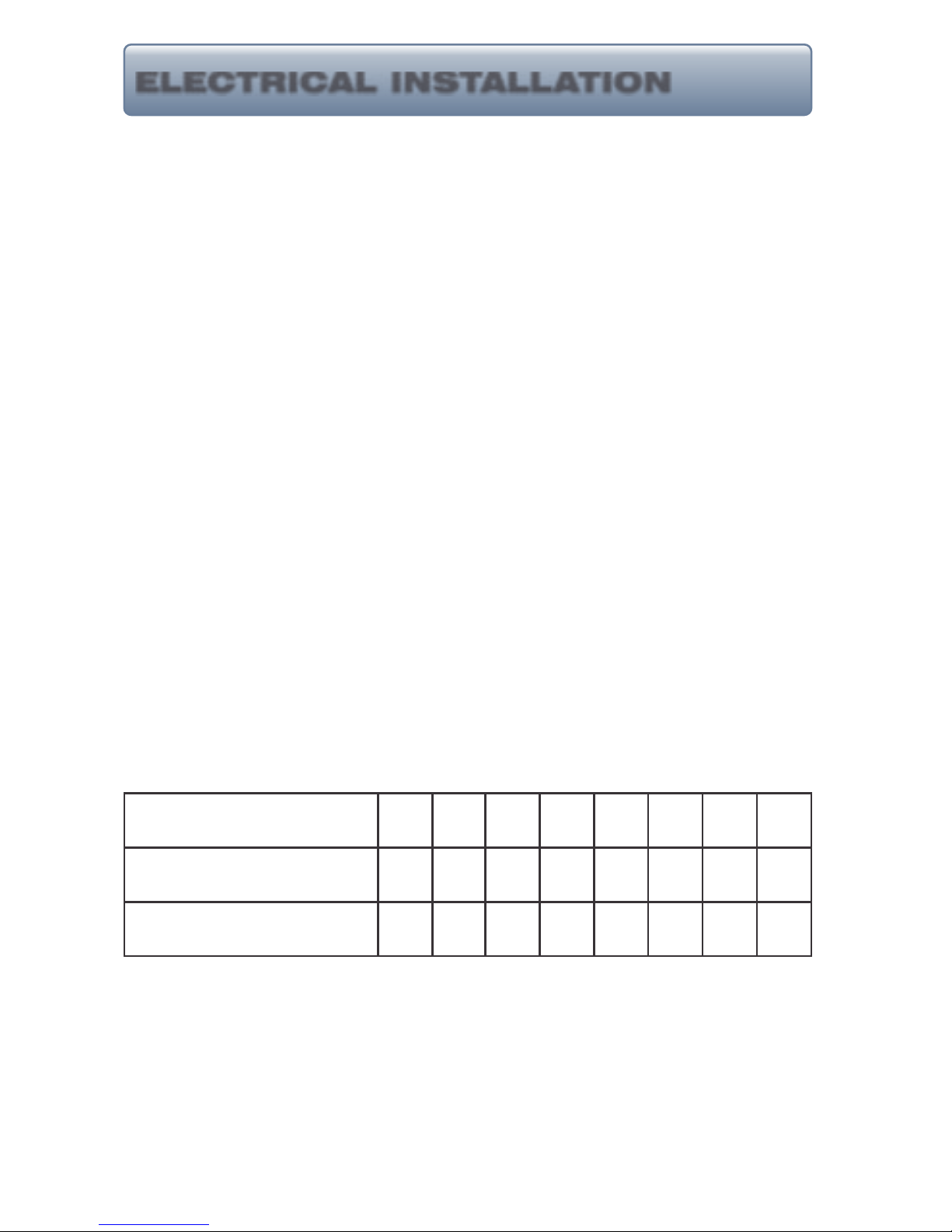
15A 20A 30A 40A 50A 60A 70A 80A
12A
16A 24A
32A 40A 48A 56A 64A
14 12 10
8
6 4
4
4
Circuit & Breaker
Rating
Maximum Amps
Minimum Wire
Size
Universal Systems require a Neutral wire therefore the service required is as follows: 120-volt
systems require a three-wire electrical service including ground, consisting of Line 1 (Black),
Neutral (White) and Ground (Green). 240-volt systems require a four wire electrical service
including ground, consisting of Line 1 (Black), Line 2 (Red), Neutral (White) and Ground
(Green).
1
ELECTRICAL INSTALLATION
2
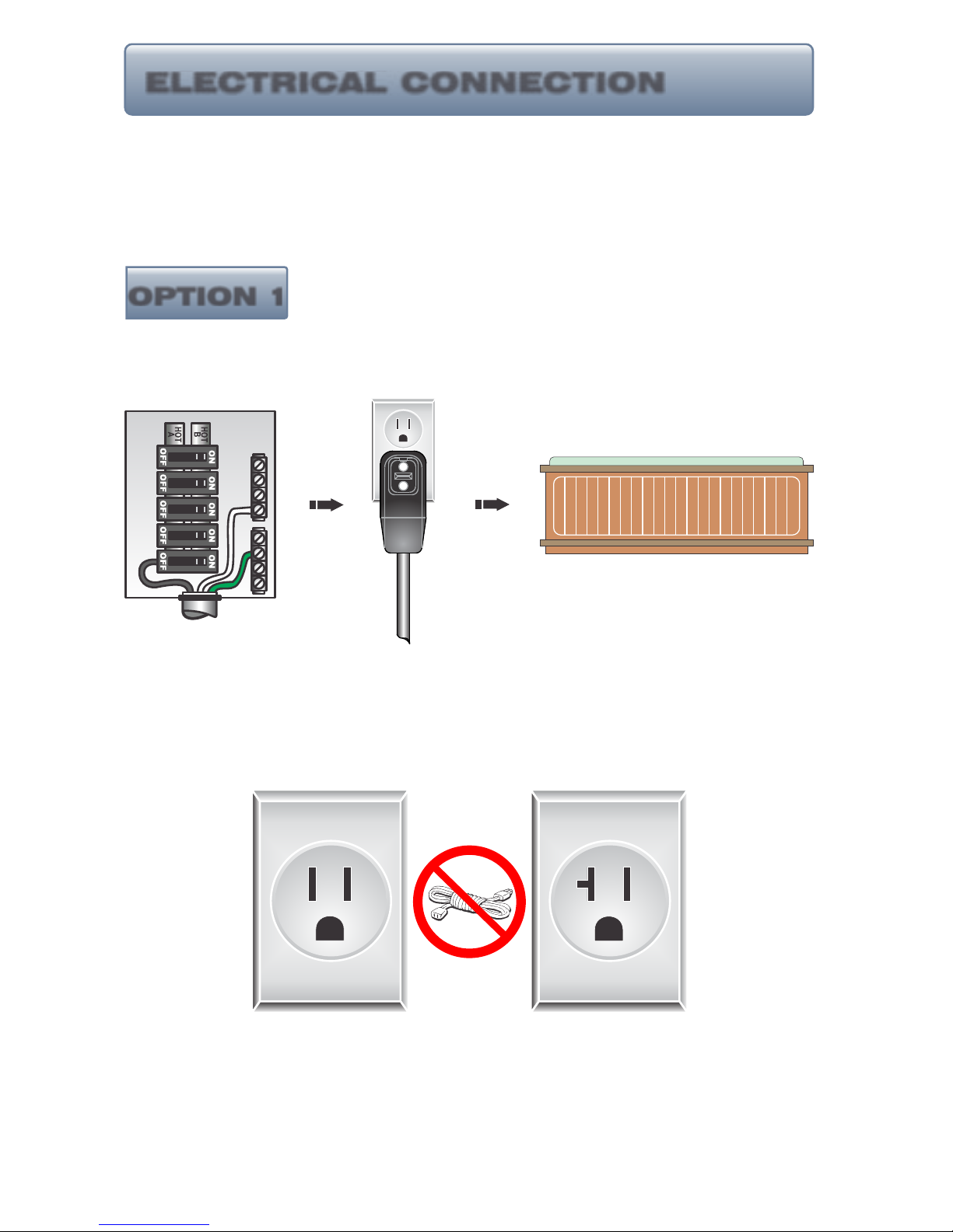
If your system was configured to include a 120VAC power cord, ensure that the proper
receptacle has been installed (a dedicated circuit is required). DO NOT under any
circumstances modify a 20 Amp plug to fit into a 15 Amp receptacle or use an extension cord.
Doing so will create hazardous conditions and/or void the warranty.
OPTION 1
20AMP CORDEND GFCI
PORTABLE SPA
DEDICATED
15A/120V OUTLET
This illustration depicts a typical 20 AMP, cord-end
GFCI installation.
(The spa must be installed on a dedicated circuit.)
DO NOT
USE AN
EXTENSION
CORD
15 AMP
RECEPTACLE
20 AMP
RECEPTACLE
Units with 15A GFCI Plug Connection
MAIN BREAKER PANEL
ELECTRICAL CONNECTION
3
PORTABLE SPA
INLINE SPA DISCONNECT
GFCI DISCONNECT
LINE 1NLINE 2
INLINE SPA DISCONNECT
20-60AMP HARDWIRED
Power from GFCI breaker installed into main service panel to a service
disconnect within line-of-site of the spa.
Power from main service panel to a GFCI subpanel within line-of-site of the
spa. (Note: Most local codes will allow a GFCI subpanel to be a disconnect.
If this is not the case in your installation, a disconnect must be provided.)
TO PORTABLE SPA
REFER TO GFCI WIRING DETAIL
REFER TO GFCI WIRING DETAIL
MAIN BREAKER PANEL
LINE 1
N
LINE 2
20-60AMP
HARDWIRED
If the manufacturer of your homes main breaker panel makes a GFCI breaker, you
may be able to add it to an open slot in the panel.
GFCI Installed in Main Service Panel
Subpanel GFCI Installed
MAIN BREAKER PANEL
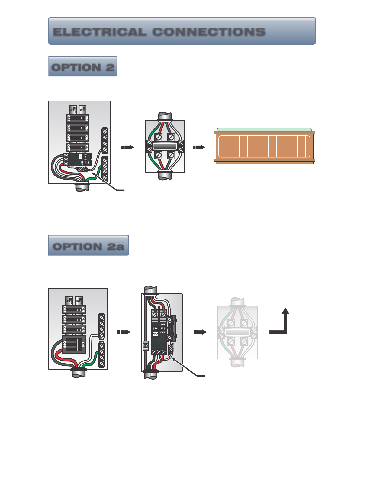
ELECTRICAL CONNECTIONS
OPTION 2
OPTION 2a
HEATER
ON
POWER
CONTROL
SWITCH
Refer to Operation
Manual for testing
and operational
procedures
Pump 1
*Pump 2
Air
*Pump 3
*Aux.
Light
Ozone
*Circ.
*Aux.
SOLID-STATE
CONTROL SYSTEM
*Optional
MAIN BREAKER PANEL
PORTABLE SPA CONTROL w/BUILT-IN GFCI
INLINE SPA DISCONNECT
BUILT-IN SYSTEM GFCI
Power from main breaker panel to service disconnect within line-of-site of the
spa to portable spa control equipped with buit-in GFCI.
Refer to the System Data Label for equipment voltage and maximum amperage draws.
Install proper size Ground Fault Circuit Interrupter (GFCI) or circuit breaker, then proper sized
wiring and bonding wire. For Power conductor size, refer to the National Electric Code Table
310-16. For Ground conductor size, refer to the National Electric Code Table 250-122.
A bonding lug has been provided on the control box to allow connection to local ground points.
To reduce the risk of electrical shock, a solid copper bonding wire should be connected from this
lug to any metal ladders, water pipes or other metal object within 5 feet of the spa.
WARNING - BE SURE THAT YOUR POWER SUPPLY CIRCUIT CAN ADEQUATELY HANDLE
THE AMPERAGE YOU SELECT.
The control input power wiring may have been provided. Following NEC and local codes in
effect at the time of installation, connect (refer to wiring diagram located on the inside of control
hinged cover) the Black wire to input Line 1, Blue wire to input Line 2 (if applicable), White wire
to Neutral and the Green wire to ground.
ELECTRICAL INSTALLATION DETAILS
!
IMPORTANT - The NEC and most local codes require that a “disconnect” be
installed within “line-of-site” of the spa.
ON
OFF
RESET
TEST
Located on left side of control box.
N
Systems with GFCI Included
Your system may have an integrated GFCI located on the left side of the control
box as shown below. If a GFCI is present there is NO need for additional GFCI
protection illustrated in options 2 & 2a.
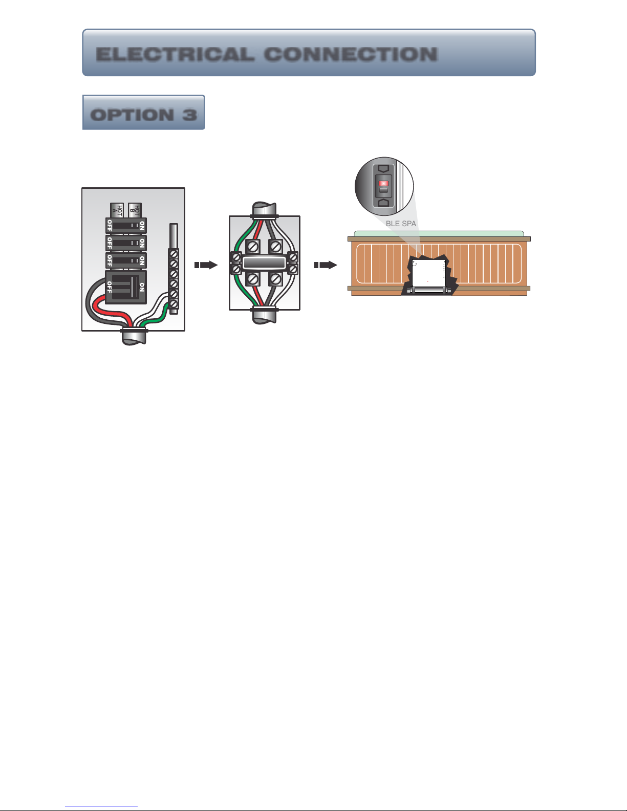
ELECTRICAL CONNECTION
OPTION 3
4
5
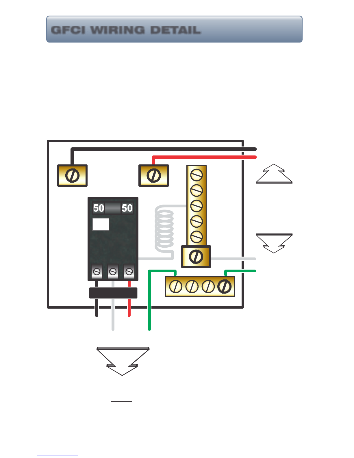
When a GFCI circuit breaker is used in the installation of your spa, it is important that it has
been properly installed. Often this component has been improperly installed causing the breaker
to trip the instant the system is turned on. Below is an illustration of a typical GFCI breaker
installation.
WARNING: Refer to Circuit Breaker Manufacturers installation instructions.
This illustration is meant to be a guide for Field Technicians and is not
intended to override or substitute the instructions supplied with the circuit
breaker.
GFCI
TEST
(Ground Fault Circuit Interrupter)
CIRCUIT BREAKER
NEUTRAL PIGTAIL
NEUTRAL BUS BAR
LINE 1
NEUTRAL
LINE 2
GROUND
GROUND BUS BAR
LINE LUG #1
LINE LUG #2
LINE 1
LINE 2
INCOMING
SERVICE
CONDUCTORS
FROM
MAIN
PANEL
NEUTRAL
GROUND
TO SPA CONTROL SYSTEM
LOAD
LOAD NEUTRAL MUST BE CONNECTED
DIRECTLY TO GFCI AS SHOWN
GFCI WIRING DETAIL
 Loading...