


Outdoor Series
INSTALLATION
& OPERATIONS
MANUAL
Covers the following CS & ES Models:
ES8848A, ES8848B, ES8848C, ES8848D, ES8848E,
ES8848J, ES8848H, ES8848J, ES8850A, ES8850B,
ES8850C, ES8850D, ES8850E, ES8850F, ES8850G,
ES8850H, ES8850J, CS8800A, CS8800B, CS8800C
JL
To ensure that the system is installed
properly, provide your electrician with
these instructions.
8800 BP Series

TABLE OF CONTENTS
Getting Started 1
Terms / Glossary 2-3
System Requirements & Considerations 4-5
NEC Guidelines & Gas/Electric Combination Systems 6-7
Electrical System Sizing 8
GFCI Breaker Wiring 9
Connecting Power to the System 10-14
Wiring Individual Components 15
Gas Heater Options 16
Pump Cord Connections 17
Air Blower Installation & System Configuration 18
Spa Light Wiring 19
Plus Ozone™ / Ozonator / Installation 20-21
Spaside Control Installation 22
Wi-Fi Module Installation 23
System Configuration Options 24-25
Your Spaside Control / Menu Navigation 26-27
System Start Up 28
System Functions, Features & Programming 29-32
Locking and Unlocking Spaside 33
Spaside Messages, Error Codes & Troubleshooting 34-41
System Data Label 42
Warranty Information 43

GETTING STARTED
For the best installation possible, review all the provided instruction materials, and share
with your electrician/installer for advanced planning. A complete understanding of what's
needed before starting work will make things go smoothly, and at the lowest possible
cost.
This manual includes complete instructions for electrical and plumbing connections,
including the addition of pumps, gas heaters, lights, system startup, troubleshooting,
and your warranty guidelines.
First identify the Equipment System (ES) or Control System (CS) from your product
label. Refer to this code when using the GFCI breaker sizing matrix, and wiring diagrams
in this manual
ES series controls include a plastic mounting base, and main system pump. The
separate quick –start sheet #85-0115-4 has detailed instructions for pack assembly, and
pump cord installation
CS series controls are designed for a wall mount application. Your electrician must follow
all local codes and restriction pertaining to placement of an accessible electrical service.
* Copies of this manual are available online at www.hydroquip.com
Your Hydro-Quip 8000 series control has a factory pre set program. Details for changing
system behavior and/or adding new components will be found in this manual.
ATTENTION!
This manual includes instructions for all options available on the ES/CS systems.
Depending on how your system is equipped, some options like Plus Ozone™, Wi,
blowers, gas heaters etc may not apply to your installation.
Warning! Make no attempt to modify, disconnect, damage or adjust the safety devices
contained in this equipment system. Alteration of safety devices can cause serious
component damage, and/or result in unsafe operation leading to personal injury or death
Save a copy of this manual
1

TERMS / GLOSSARY
AC Connection
Additional Panel Button
Amperage Requirement
AUX PCB
Auxiliary Pump
Blower
Bonding Wire
™
BWA APP
Copper Conductors
Dedicated Circuit
Default Programming
Dip Switch
Dip Switch Banks
Discharge
Alternating Current connection point (typically high voltage)
Refers to HQ PT# 34-0224. Required for 3rd pump operation
The accumulated total amperage of all items to be placed on a
single breaker
Smaller daughter board connected to main PCB
A pump that has been added to the original equipment system (ie Aux
pump #2 & #3)
Appliance providing compressed air for the purpose of massage therapy
Continuous bare copper wire connecting all metallic object and electrical
components to the equipment & ground rod
Downloadable Balboa Water Application for wireless system control
Electrical wires made from copper alloy materials
An electrical supply to a remote location, having breaker protection and
no additional branch or service connections
The standard position or programming in which the system is tested
and leaves the factory
Movable programming switch located within a switch-bank (on PCB)
Set of switches used to change operational logic and system behavior
(on PCB)
Pump exit side (piping placed on pressure side of pump)
Dual Source Wiring
Gas Heater Control Circuit
GFCI Breaker
GFCI breaker #1
GFCI breaker #2
Heater Input Leads
Jumper Pins
Electrical power supplied by two individual wiring sources (two breakers)
Wiring provided inside gas heaters, that can be connected to 8000
systems for operational control. Commonly called a fireman circuit
Ground Fault Circuit Interrupter. Specialty breaker with a detection and
reaction device to interrupt power when current leaking is detected to
ground
Main 8000 system breaker, required 4 wires with incorporated “Neutral”
Optional breaker for independent heater operation. Required 3-wire
connection, without “Neutral”
Provided wires for connection of heaters in the dual source
configuration
Circuit board electrical posts for logic changes.
2

TERMS / GLOSSARY
KW
Line of Sight
Logic Jumper
Liquid Tight Conduit
Main Control
Main Pump or Pump #1
NEC
PCB
Persistent Memory
Plus Ozone™/Ozonator
Priming
Pump Amperage
Pump Pot/Basket
Single Source Wiring
Kilowatt. Heater resistance rating used for identifying energy consumption.
A clear and unobstructed path, in which an object or item can be spotted from
or near the spas edge.
Movable coupling located on the jumper pins for changing operational
behavior
Tubing that resists water and debris penetration, made specifically for
wiring
In reference to the 8000 series control box, with factory provided components
System provided pump used for heating and filtration
National Electrical Code. Regulations for design and materials on electrical
installation.
Printed Circuit Board (refers to main board)
Programming that remains unchanged, until the power is turned off and back
on
Appliance designed for spa water sanitation
Initial pump operation until the air is evacuated from the pump and supply
lines
The highest amperage measured, when the pump is under full load
condition
Reservoir mounted to the pump with removable lid and strainer basket
Electrical power supplied by a single wiring source and breaker
(one breaker)
Sub Panel
Suction
System Data Label
System Disconnect
Terminal Strip
Total System Amps
Wi-Fi Enabled
An electrical service box mounted remotely from the main house power panel
Pump front inlet side (piping between spa suctions and pump pot)
Label placed on control box providing serial identification, and vital data
An easy and safe means of 100% electrical disconnection, without
obstruction or the need for tools. See NEC and UL qualifications for approved
devices.
Electrical connection point for components within the PCB cabinet
Highest amperage measured when all components are operating
simultaneously
Having the capacity to control using a wireless connection
3
SYSTEM INSTALLATION REQUIREMENTS
The Hydro-Quip 8000 Series Solid-State Systems were designed for indoor or outdoor installations.
This equipment may be used for both inground and above ground spas/hot tubs.
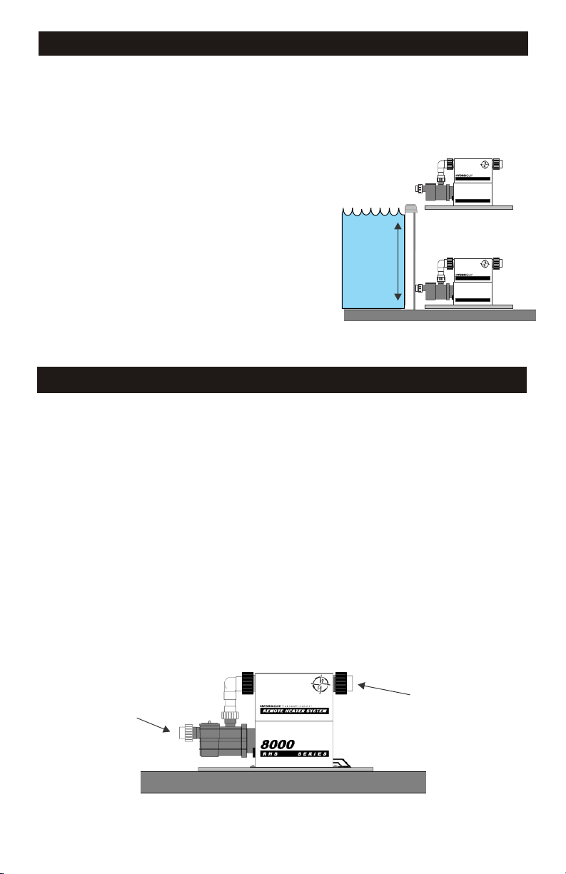
The Equipment System must be installed on a firm, level
surface (ie: concrete or plastic base)
The area where the system is installed must have adequate
Above Water Level
drainage to prevent flooding of the equipment under all
circumstances.
For performance reasons locate the system as close to the
spa/hot tub as practical. (Consult local codes for minimum
REMOTE HEATER SYSTEM
8000
RHS SERIES
distance between equipment and spa)
Provide adequate access around and above the System for
service and maintenance. Three (3’) of clearance around the
equipment is recommended.
The pump(s) provided with the system may or may not be
self-priming. Pumps that are NOT self priming must be
installed BELOW water level or they will not prime.
The Spaside control has a 50’ cord length. Plan routing
distance between the equipment and vessel to be less than
44ft.
Water Level
REMOTE HEATER SYSTEM
8000
RHS SERIES
Below Water Level
(Flooded Suction)
PLUMBING INSTALLATION INSTRUCTIONS
To assure adequate performance, the use of 2” piping is recommended.
There may be 3 or 4 separate plumbing systems in the spa. Verify the function of each pipe.
1) Suction System Plumbing - this plumbing will connect to the spa’s skimmer, main drain and
suction fittings. This plumbing connects to the front end of each pump.
2) Discharge System Plumbing - this plumbing will go to the spa’s hydrotherapy jet and massage
fittings. This plumbing connects to the open end of the heater on your Equipment System.
3) Air Blower Plumbing - this plumbing will go to an air channel under the floor, or to an air distribution
manifold of the spa. This plumbing connects only to an air blower.
4) Aux Pump Plumbing - When more pumps are added, this piping will not interconnect with the
heater control system. Follow the spa/hot tub manufactures instruction for connection, and safety
suction requirement
5) Understand in advance the spa manufactures plumbing design for ozone delivery and make
accommodation in your plumbing plan.
To allow for safe operation of the spa/hot tub, the suction fittings must be agency approved and rated
Max Flow capacity.
After plumbing is complete, secure the Hydro-Quip Equipment System with the appropriate
hardware.
Suction
Discharge
Refer to plumbing schematic Fig.1 on page 15
4

INSTALLATION CONSIDERATIONS
The Hydro-Quip 8000 series incorporates the most advanced controls in the industry, and
are designed for years of trouble free operation. However, for year round success, review
these design recommendations for extreme weather areas.
*For best results, review this manual completely before starting your project.
Hot weather conditions
Water temperatures can be elevated from high outside “ambient” temperatures. If this
occurs, remove the insulating cover and add cool water until the heat has dissipated to a
safe level
Hot temperatures and/or direct sunlight to the equipment system can cause temporary
operational problems.
Pumps are equipped with special overload devises to self protect when encountering
extreme heat conditions. All motors are equipt with an automatic reset device, and will
resume operation when they become cool. Pumps can be enclosed, but require adequate
ventilation
Direct sunlight on equipment can bring temperatures beyond the allowable point for
circuits to function correctly. The system will shut off into a protection mode (see
troubleshooting guide.) To prevent this condition, plan an equipment cover that
incorporates shade, access and ventilation
Freezing weather conditions
If you wish to utilize/operate your system during seasons that may experience freezing
temperatures, please incorporate pipe insulation, draining capabilities and incorporate
an equipment cover that protects from snow and freezing rain. In all cases standing water,
and snow should not be allowed to accumulate in or around the equipment.
If you wish to winterize your spa/hot tub, please contact your spa/hot tub manufacturer or
local area pool/spa/hot tub professional for details.
In all cases make a plan for system draining in case of a power loss. Where possible,
design plumbing drains and disconnects to evacuate water before it becomes frozen and
does system damage.
Note the 8000 systems incorporate a freeze sensing technology, that will automatically
operate the pumps when temperatures drop below 43F. Moving the water will not allow
pipes and equipment to form ice.
5

ELECTRICAL INSTALLATION
NOTICE! Before attempting installation of this equipment system, read all the
information contained in this manual, and confirm the installing electrician understands
and follows all national and local codes and safety instructions.
All connections must be made by a qualified and licensed electrician in accordance with
the National Electrical Code (NEC article 680 Canadian Electric Code, and with any local
codes in effect at the time of installation.
All connections must be made according to the electrical installation label on the outside
of the system box (see page 33) Follow all instructions provided in this manual, and at
labeled connections. If your electrician in unclear on how to correctly connect this
equipment, call your system supplier. Note that damage caused by mistakes can be
costly, and invalidate your warranty.
A GFCI (Ground fault circuit interrupter) breaker is a mandatory electrical device required
for installation on all pool/spa applications as specified in the National Electrical Code
Article 680-42.
The GFCI must be properly sized, and be connected with the appropriate sized wire per
NEC Code Table 310-16. All ground wires must be connected per NEC Table 250-122
Follow the instructions provided in this manual (see pages 7-9) for proper location and
connection of this safety device
This equipment requires a dedicated electrical supply circuit, with no other appliances or
lights connected.
IMPORTANT – The NEC and most local codes require that an electrical “disconnect” be
installed within “line of site” of the spa
Use copper conductors only, with grounding wire properly sized per the National Electric
Code table 250-95.
A bonding lug has been provided on the control box, allowing connection to local ground
points. To reduce the risk of electrical shock, use only a properly sized copper bonding
wire from this lug to all metal ladders, water pipes and other metallic objects within 5 feet
of the spa/hot tubs edge.
CAUTION: Do not connect or disconnect any components while the power is on.
All connections must be done with the power off as it may cause damage to the
system.
**Any resulting damages are not covered under manufacturer’s warranty**
CAUTION: Damage may occur to the circuit board and spaside if the spaside
plug is not properly aligned to the receptacle on the circuit board or if the
spaside plug is connected or disconnected while the power is on.
**Any resulting damages are not covered under manufacturer’s warranty**
6

ELECTRICAL INSTALLATION
This equipment system has been100% factory tested for quality and reliability prior to
shipping. Care should be taken on all electrical connections to avoid damage to the system
circuit board, and added components. Damage caused by accidents, improper wiring
configurations and/or abuse voids your warranty.
Start by having your electrician select a wiring configuration that best fits your total system
needs. (see the GFCI breaker sizing matrix on page 8)
Due to the availability of GFCI breaker sizes, and your electrical supply requirement, some
systems require a second independent or “dual” power source, to supply the electric heater
separately. Diagrams for independent heater wiring are provided in this manual.
Note; 5.5kw systems using a single source power supply will not allow electric heater
operation when pumps are in high speed. See system programming to change operation if
available.
System Type Heater size Connection type
Gas heat none Single source power supply
Electrical heat 5.5kw Single source power supply
Electrical heat 5.5kw Dual source power supply
Electrical heat 11.0kw Dual source power supply
Gas/Electric Combo 5.5 or 11kw/Gas Single Source power supply
All Hydro-Quip 8000 series control systems require a 4 wire electrical supply, incorporating
a “Neutral” wire for operation. Electric heaters being powered independently in the “dual”
circuit configuration do not require a neutral wire supply. This is clearly explained in the
wiring diagrams.
For gas heaters electrical connection, consult your gas heaters supplier manual, and note
in this manual contains important wiring instructions for control and operation of the gas
heaters fireman circuit.
Gas and electric heater combination
When faster heat recovery is desired, or a redundant heat source is a priority, it’s possible
to install both a gas and electric heater on the same 8000 series system.
Default programming allows both the gas heater control circuit (page 15) and electric
heater circuit to operate simultaneously. Input from both heat sources will speed up heating
times, and also provide an operating alternate if one source becomes disabled. You must
follow all installation instructions for both the gas heater, and electric heater plumbing and
wiring requirements to successfully connect. No PCB programming change is required.
7
GFCI BREAKER SIZING MATRIX
240V Single source wiring (One breaker required)
Syste m or de r
code on labe l
ES8848G, H, J
ES8850G, H, J
CS8800C
ES8848G, H, J
ES8850G, H, J
CS8800C
ES8848G, H, J
ES8850G, H, J
CS8800C
ES8848D, E
ES8850D, E
CS8800B
ES8848D, E
ES8850D, E
CS8800B
Syste m
heater type
Gas x _ _ 17
{
Gas x
{
Gas x x x
{
5.5kw x _ _
{
5.5kw x x _
{
240V Dual source wiring with separate heater electrical supply
(Two breakers required)
System orde r
code on labe l
ES8848D, E x x x 43amp s yste m 50 am p #1
ES8850D, E, F 5.5k w _ _ _ 24amp h e ate r 30 am p #2
CS8800B
ES8848A, B, C x _ _ 17amp s yste m 20 am p #1
ES8850A, B, C 11kw _ _ 46am p he ater 60 am p #2
CS8800A
ES8848A, B, C x x _ 30amp sys tem 40 amp #1
ES8850A, B, C 11kw _ _ _ 46amp he ate r 60 am p #2
CS8800A
ES8848A, B, C x x x 43amp sys tem 50 am p #1
ES8850A, B, C 11kw _ _ _ 46amp he ate r 60 am p #2
CS8800A
System
he ate r type
{
{
{
{
Pump 1 &
Syste m
17A Max
Pum p 1 &
System
17A Max
Aux. pum p- 2
12A max
Aux. pu m p- 2
12A m ax
Aux. pum p- 3
12A max
x _ 30
Aux. pu m p- 3
12A m ax
Total s yste m
Am ps
43 50 amp #1 13
41 50 amp #1 12
54 60 amp #1 12
Total sys tem
Am ps
GFCI Break e r Page
20 amp #1
30 amp #1 13
GFCI Bre ak e r Page
13
14
14
14
13
13
11
12
10
10
10
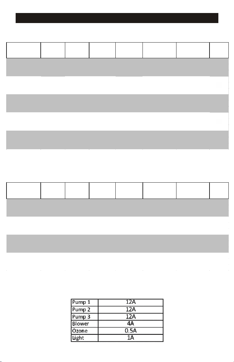
**IMPORTANT NOTE**
Max Amp Per Circuits
8
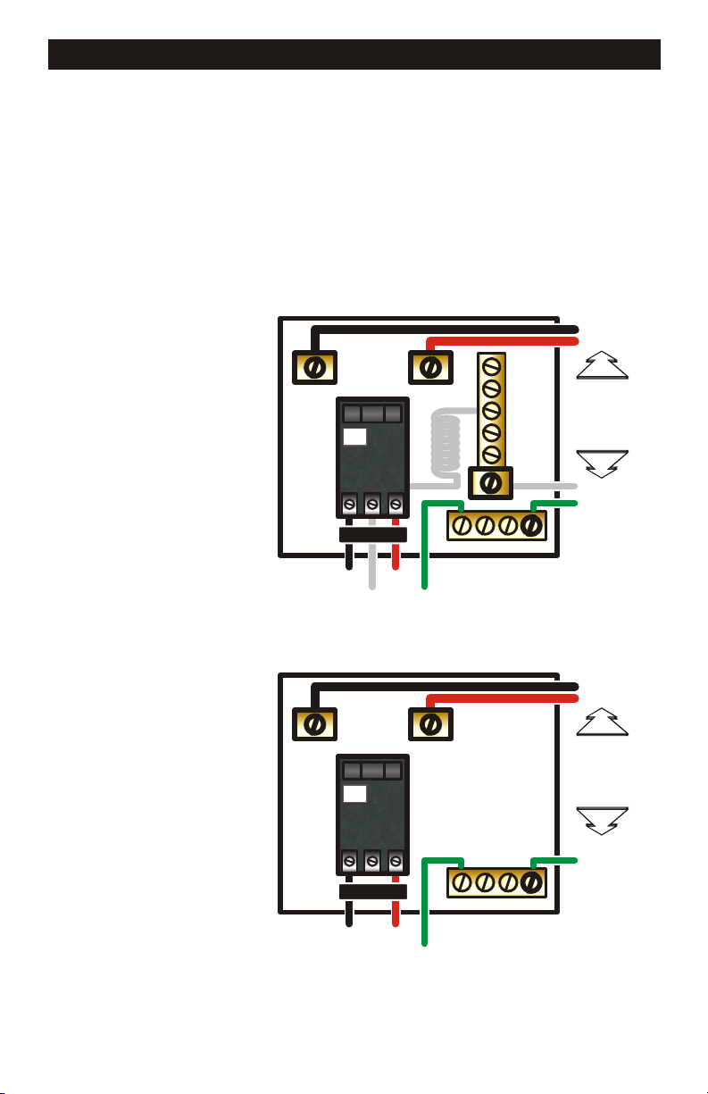
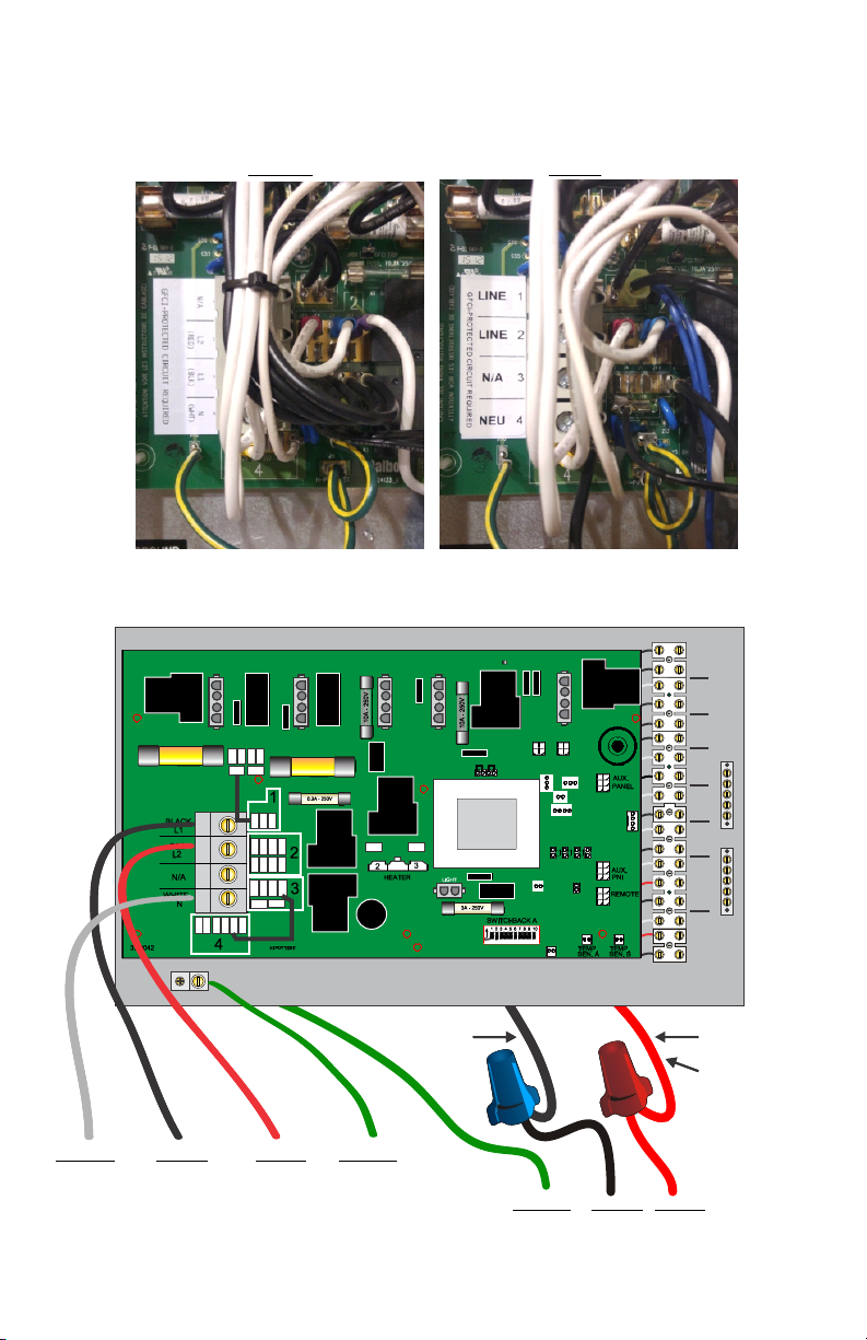
GFCI BREAKER WIRING DETAIL
Improperly wired GFCI breakers are the leading cause of immediate GFCI tripping. It
is important that your system be wired properly, reference the illustrations below for
guidelines.
WARNING: Refer to the circuit breaker manufacturer’s installation instructions. This
illustration is meant to be a guideline, and not meant to override or substitute the
instructions supplied by the breaker manufacturer
LINE 1
LINE 2
GFCI BREAKER #1
(240v 4-wire with neutral)
GFCI BREAKER #2
(240v 3-Wire)
For Independent Heater
LINE LUG #1
LINE LUG #1
LINE LUG #2
TEST
GFCI
(Ground Fault Circuit Interrupter)
CIRCUIT BREAKER
LO A D
LOAD
LOAD
NEUTRAL
GROUND
TO SPA EQUIPMENT
LINE LUG #2
TEST
GFCI
(Ground Fault Circuit Interrupter)
CIRCUIT BREAKER
LO A D
NEUTRAL PIGTAIL
GROUND BUS BAR
GROUND BUS BAR
CONDUCTORS
NEUTRAL BUS BAR
CONDUCTORS
INCOMING
SERVICE
FROM
MAIN
PANEL
NEUTRAL
GROUND
LINE 1
LINE 2
INCOMING
SERVICE
FROM
MAIN
PANEL
GROUND
LOAD LOAD
GROUND
TO SPA EQUIPMENT
9
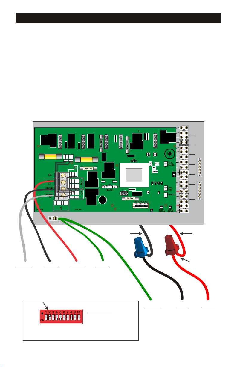
208V ELECTRICAL CONNECTIONS CONSIDERATIONS
IMPORTANT 208V INFORMATION
The system has the capability to operate on 208V provided certain changes are made
to the circuit board transformer and input wiring. When operating on 208V a compatible
pump must be used. A compatible pump would be either 120V or marked specically
for use with 208V.
**240V pumps provided by Hydro-Quip are NOT 208V compatible**
Below is an illustration of the system wiring as shipped from Hydro-Quip. Follow the
instructions on page #X and the illustration on page #X to make the system compatible
with 208V incoming power.
SWITCH
FIREMANS
L L
120V
LIGHT
J35
FUSE 30A
J34
J56
J57
J55
J59
FUSE 30A
J41J60
J51
J52
J98
J72
J42J3J61
J37J4J1
J47
J36
J12
J88
J62
J58J53
J45
J79
J54
J77
J75
J78
J49 J48
MAINMAIN
L C
L C
H L C
H L C L C L L L C
LIGHT
OZONE 12V
GROUNDGROUND
BLOWER
PUMP 3
PUMP 1 PUMP 2
GROUND
Neutral Line 1 Line 2 Ground
GFCI BREAKER #1
(240v 4-Wire only)
see page 8 for breaker sizing
Fig. A
SwtichBank ON:
A2: Add 1 HS Pump with heat
A3: Add 2 HS pumps with heat
A4: Add 4 HS pumps with heat
Move dip switch #2 - #4 to the ON position
to allow high speed pump(s) and heater to
function simultaneously
10
Black
Red
Heater main wires
electric heater models
only
Ground Line 1 Line 2
GFCI BREAKER #2
(240v 3-Wire only)
see page 8 for breaker sizing

Instruction
Wiring Instruction from 220-240v. to 208v. power supply
Ÿ Information provided for Balboa BP-2000 system board only
Ÿ 1 logic jumper P/N 34-20564 is included with this instruction
Ÿ Terminal Block wiring label
Ÿ New diagram# 5195-5197
WARNING! System power must be off when removing or installing logic jumpers
Logic jumper(s) must be programmed to match incoming power supply voltage.
Use these steps if a programming change is required
Step #1 Disconnect power
Step #2 Locate transformer programing bank at position J24 on PCB
Step #3 Conrm system supply voltage with your electrician.
Step #4 Use diagrams below to correctly place logic jumper(s) to match system supply voltage
(Dia #1 = 220-240V. ) (Dia #2 = 208V)
Step #5 Remove and Discard the jumper wire connecting J41 to J12
Step #6 Remove and Discard the jumper wire connecting J51 to J88
Step #7 The wire currently connected to J36 must be relocated to J51
Step #8 The wire currently connected to J52 must be relocated to J75
Step #9 The wire currently connected to J58 must be relocated to J52
Step #10 The wire currently connected to J49 must be relocated to J98
BEFORE AFTER
...connued from previous page
Step #11 New Incoming Power label provided must be applied to circuit board (illustraon below)
Step #12 This instrucon sheet and new diagram must be inserted in the faceplate slip if one is not
currently present
Below is an illustration of the system transformer and wiring converted and ready
for 208V use.
SWITCH
SWITCH
FIREMANS
FIREMANS
L L
L L
120V
120V
LIGHT
LIGHT
J35
J34
J35
FUSE 30A
FUSE 30A
J56
J57
J55
J59
J56
J57
J55
J59
FUSE 30A
FUSE 30A
J41J60
J41J60
J51
J52
J98
J51
J52
J98
J49 J48
J72
J42J3J61
J72
J42J3J61
J37J4J1
J47
J37J4J1
J47
J36
J12
J88
J62
J36
J12
J88
J62
J58J53
J58J53
J45
J45
J79
J54
J77
J75
J78
J79
J54
J77
J75
J78
J49 J48
J34
MAINMAIN
MAINMAIN
L C
L C
L C
L C
H L C
H L C
H L C L C L L L C
H L C L C L L L C
LIGHT
LIGHT
OZONE 12V
OZONE 12V
GROUNDGROUND
GROUNDGROUND
BLOWER
BLOWER
PUMP 3
PUMP 3
PUMP 1 PUMP 2
PUMP 1 PUMP 2
GROUND
GROUND
Neutral Line 1 Line 2 Ground
GFCI BREAKER #1
(208v-240v 4-Wire only)
see page 8 for breaker sizing
10
Black
Ground Line 1 Line 2
GFCI BREAKER #2
(208v-240v 3-Wire only)
see page 8 for breaker sizing
Red
Heater main wires
Heater main wires
electric heater models
electric heater models
only
only
208V ELECTRICAL CONNECTIONS CONSIDERATIONS
Below is an illustration of the system transformer and wiring converted and ready for
Below is an illustration of the system transformer and wiring converted and ready for
208V use.
208V use.
Note wiring changes at the input terminal block and at the voltage conversion jumper(s)
Note wiring changes at the input terminal block and at the voltage conversion jumper(s)
above the transformer.
above the transformer.
SWITCH
SWITCH
FIREMANS
FIREMANS
L L
L L
120V
120V
LIGHT
LIGHT
J35
J34
J35
FUSE 30A
FUSE 30A
J34
MAINMAIN
J56
J57
J55
J59
J56
J57
J55
J59
FUSE 30A
FUSE 30A
J41J60
J41J60
J51
J52
J98
J51
J52
J98
J49 J48
J72
J42J3J61
J72
J42J3J61
J37J4J1
J47
J37J4J1
J47
J36
J12
J88
J62
J36
J12
J88
J62
J58J53
J58J53
J45
J45
J79
J54
J77
J75
J78
J79
J54
J77
J75
J78
J49 J48
MAINMAIN
L C
L C
L C
L C
H L C
H L C
H L C L C L L L C
H L C L C L L L C
LIGHT
LIGHT
OZONE 12V
OZONE 12V
GROUNDGROUND
GROUNDGROUND
BLOWER
BLOWER
PUMP 3
PUMP 3
PUMP 1 PUMP 2
PUMP 1 PUMP 2
GROUND
GROUND
Neutral Line 1 Line 2 Ground
Neutral Line 1 Line 2 Ground
GFCI BREAKER #1
GFCI BREAKER #1
(208v-240v 4-Wire only)
(208v-240v 4-Wire only)
see page 8 for breaker sizing
see page 8 for breaker sizing
Fig. A
SwtichBank ON:
A2: Add 1 HS Pump with heat
A3: Add 2 HS pumps with heat
A4: Add 4 HS pumps with heat
Move dip switch #2 - #4 to the ON position
to allow high speed pump(s) and heater to
function simultaneously
10
Black
Black
Red
Red
Heater main wires
Heater main wires
electric heater models
electric heater models
only
only
Ground Line 1 Line 2
Ground Line 1 Line 2
GFCI BREAKER #2
GFCI BREAKER #2
(208v-240v 3-Wire only)
(208v-240v 3-Wire only)
see page 8 for breaker sizing
see page 8 for breaker sizing
11KW ELECTRICAL CONNECTIONS
11KW electric heat “Main” control system wiring diagram
SINGLE SOURCE WIRE CONNECTION
For correct wire and GFCI breaker sizing, Reference the GFCI breaker sizing matrix
page in this manual
Factory programming will prevent the heater and high speed pump from operating
simultaneously.
FOR SYSTEM MODEL CODES (Label located on outside of box)
ES8848A ES8848B ES8848C CS8800A
ES8850A ES8850B ES8850C
SWITCH
FIREMANS
L L
120V
LIGHT
J35
FUSE 30A
FUSE 30A
J34
MAINMAIN
L C
L C
H L C
LIGHT
OZONE 12V
GROUNDGROUND
BLOWER
PUMP 3
GROUND
Black
Red
HEATER MAIN WIRES
Neutral Line 1 Line 2 Ground
GFCI BREAKER #1
(240v 4-Wire only)
see page 8 for breaker sizing
11
H L C L C L L L C
PUMP 1 PUMP 2

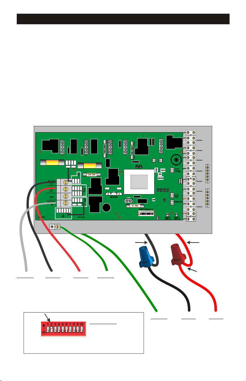
5.5KW ELECTRICAL CONNECTIONS
5.5KW electric heat “Main” control with independent heater wiring
DUAL SOURCE WIRE CONNECTION
For correct GFCI breaker sizing, Reference the GFCI breaker sizing matrix page in
this manual
Programming allowing heater and high speed pump operation simultaneously
requires “dip switch” change on board (see figure below)
FOR SYSTEM MODEL CODES (Label located on outside of box)
ES8848D ES8848E ES8850F
ES8850D ES8850E CS8800B
SWITCH
FIREMANS
L L
120V
LIGHT
J35
FUSE 30A
FUSE 30A
J34
MAINMAIN
L C
L C
LIGHT
OZONE 12V
GROUNDGROUND
BLOWER
PUMP 3
GROUND
Neutral Line 1 Line 2 Ground
GFCI BREAKER #1
(240v 4-Wire only)
see page 8 for breaker sizing
Fig. A
SwtichBank ON:
A2: Add 1 HS Pump with heat
A3: Add 2 HS pumps with heat
A4: Add 4 HS pumps with heat
Move dip switch #2 - #4 to the ON position
to allow high speed pump(s) and heater to
function simultaneously
12
Black
H L C
PUMP 1 PUMP 2
H L C L C L L L C
Blue
Heater main wires
Ground Line 1 Line 2
GFCI BREAKER #2
(240v 3-Wire only)
see page 8 for breaker sizing

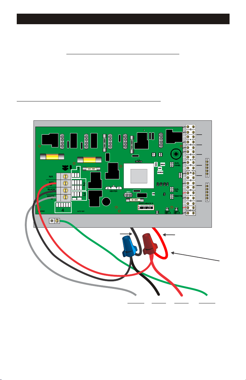
5.5KW ELECTRICAL CONNECTIONS
5.5KW electric heat “Main” control system wiring diagram
SINGLE SOURCE WIRE CONNECTION
For correct wire and GFCI breaker sizing, Reference the GFCI breaker sizing matrix
page in this manual
Factory programming will prevent the heater and high speed pump from operating
simultaneously
FOR SYSTEM MODEL CODES (Label located on outside of box)
ES8848D ES8848E ES8850F
ES8850D ES8850E CS8800B
SWITCH
FIREMANS
L L
120V
LIGHT
J35
FUSE 30A
FUSE 30A
J34
MAINMAIN
L C
L C
H L C
LIGHT
OZONE 12V
GROUNDGROUND
BLOWER
PUMP 3
GROUND
Black
Blue
HEATER MAIN WIRES
Neutral Line 1 Line 2 Ground
GFCI BREAKER #1
(240v 4-Wire only)
see page 8 for breaker sizing
13
H L C L C L L L C
PUMP 1 PUMP 2

GAS ELECTRICAL CONNECTIONS
Remote gas heat “Main” control system wiring diagram
SINGLE SOURCE WIRE CONNECTION
For correct wire and GFCI breaker sizing, Reference the GFCI breaker sizing matrix
page in this manual
FOR SYSTEM MODEL CODES (Label located on outside of box)
ES8848G ES8848H ES8848J CS8800C
ES8850G ES8850H ES8850J
FUSE 30A
FUSE 30A
J35
J34
MAINMAIN
Gas heater
internal control
see page 15
SWITCH
FIREMANS
L L
120V
LIGHT
LIGHT
OZONE 12V
GROUNDGROUND
L C
BLOWER
L C
PUMP 3
GROUND
Neutral Line 1 Line 2 Ground
GFCI BREAKER #1
(240v 4-Wire only)
see page 8 for breaker sizing
14
Fig. A
Move dip switch #7 to the ON position to
allow 5 minute gas heater cool down
H L C
H L C L C L L L C
PUMP 1 PUMP 2

COMPONENT CONNECTION
The system is set up to have components hardwired to a terminal strip inside the upper enclosure.
Liquid tight conduit must be used on all externally added field connections exposed to the weather.
Route and connect the conduit to the knock-outs in the back of the lower box. The wires will then
enter the bottom of the upper box through another set of knock-outs. Connect the component(s)
accordingly to the corresponding position on the terminal strip and tighten securely. Refer to the
included wiring diagram as needed. All components not included with the system are set at the
factory for 120V. Verify the voltage of the additional component(s) and adjust supply voltage if
necessary by referring to System Configuration on page 10.
*Systems equipped with blowers and Plus Ozone options come pre connected to the terminal strip™
SWITCH
FIREMANS
FUSE 30A
FUSE 30A
L L
J35
J34
MAINMAIN
L C
L C
H L C
H L C L C L L L C
120V
LIGHT
LIGHT
OZONE 12V
GROUNDGROUND
BLOWER
PUMP 3
PUMP 1 PUMP 2
Lighting
Lighting
Sanitation
Air Blower
Aux. Pump
Aux. Pump
Primary Pump
GROUND
BLOWER
UPPER BOX
15
LOWER BOX
LIQUID-TIGHT
CONDUIT
TO EXTERNAL
COMPONENT

GAS HEATER CONNECTION
Warning: Do not install a spa that utilizes a natural gas or propane heater without proper
venting. These heaters require adequate ventilation and must be installed according to the
heater manufacturers instructions and to local building codes.
Warning: Gas heaters MUST be installed in the plumbing AFTER the control system as
shown below. Fig.1
Note: Many gas heaters require a separate electrical service for proper
operation, the Hydro-Quip “Gas Heater Control Circuit” does NOT
provide voltage to any gas heater circuits. Always refer to the manual
included with your gas heater for proper installation.
Flow
Spa/Hot Tub
Flow
Jets
Pump 2 Pump 3 Blower
Flow
Jets
Flow
Flow
Equipment System
ANALU & TATA
REMOTE HEATER SYSTEM
8000
RHS SERIES
Pressure Filter
Flow
TYPICAL PLUMBING LAYOUT
Gas Heater Control Circuit
Your control system contains a Gas Heater Control Circuit Fig.2. This circuit is a passive
or “dry contact” circuit, do not apply line voltage to this circuit. Connect this circuit to the
gas heater’s Fireman Switch or Fireman Circuit. Refer to the instructions provided with
your gas heater to identify the circuit / switch and correct wiring connection. Additional
programming may be required to the gas heater to utilize an auxiliary control system.
Gas Heater
Fig.1
Flow
SWITCH
FIREMANS
L L
H L C L C
12V
LIGHT
OZONE
PUMP 1
GROUND
To Gas Heater
Fireman Switch*
or
Fireman Circuit*
Inside control box
Terminal connection.
Fig.2
IMPORTANT: Applying line voltage to Gas Heater Control Circuit voids all
warranty.
16

PUMP CORD INSTALLATION
The equipment system has been provided with a pump power cord and liquid-tight
conduit assembly. This is to be used on the main 2-speed pump supplied with the
system. Any other components or accessories attached to the equipment system
should be attached in a similar manner.
Follow the simple instructions below to quickly attach the cord assy to the pump:
Cord Assy included for Pump 1
1) Remove the terminal cover off the
back off the pump
3) Route the power wires through the conduit hole and pull
toward you to allow for the cord assy to be rotated for tightening.
4) While holding the wires as shown
thread the liquid-tight connector into the
pump until secure then connect the
power wires to the pump per the label
on the pump.
WIRING NOTE:
RED = LOW
BLACK = HIGH
WHITE = COMMON
GREEN = GROUND
17
2) Remove the conduit hole cover
5) Route the other end of the conduit
through the empty knock-out and secure
with lock-nut. The cord inside will route
up to the terminal strip inside the upper
portion of the enclosure.

AIR BLOWER INSTALLATION (Optional)
PUMP 1 RED
PUMP 2 VIOLET
BLOWER BLUE
OZONE YELLOW
CAUTION: The air blower must be connected ONLY to the
spa’s air distribution plumbing. Connecting the air blower to the
air piping associated with the hydrotherapy jets will create a
hazzard by providing a path for high-pressure water to be
forced into the blower motor. This will result in damage to the air
blower, and create an electrical shock hazzard.
18” Above
Maximum Water
Level
Check Valve*
Above
Water
Level
ANALU D.
JASON LUGO
Ÿ The air blower must be installed to ensure that water
cann ot e nte r the air blo we r mot or. Thi s ca n be
accomplished by installing a single or double air loop that
incorporates a check valve.
Below
Water
Level
Check*
Valve
To
Blower
SYSTEM CONFIGURATION
This System was pre-configured by the manufacturer as follows:
Pump 1: 240V Pump 3: 240V Ozone: 120V
Pump 2: 240V Blower: 240V
CHANGING CONFIGURATIONS
Below are illustrations and instructions for converting the universal circuits of your control.
Hydro-Quip utilizes color coded connectors to help identify each circuit. Simply locate the
colored connector on the Neutral (white) wire from each component receptacle on the PCB.
Using the wiring diagram provided with each control (located inside of cover), remove the Neutral
connector from its Block 4 / Neutral position and reconnect to an empty position at the Block 2 /
Line 2 connection block. Once accomplished the conversion is complete, repeat these steps for
each component that operates on 240V.
COMPONENT COLOR CODE
(1) Remove connector from Block 4 connection
(2) Reinstall connector onto Block 2 connection
240V
Block 2
120V
RED AC
Block 4
WHT AC
18

SPA LIGHT INSTALLATION
To offer the most flexibility, Hydro-Quip configures each 8000 Series system so that it can
accept a 120-Volt light and/or 12-Volt light. A terminal block has been provided for connection
purposes.
Connect your light using the
illustration below.
GR-L1-N
120-Volt Light
Connection
19
L1-N
12-Volt Light
Connection

Plus Ozone Option
Systems equipped with the factory installed Plus Ozone™ option are identied with both a visible
green label on the front access door “A” and a generator connection barb extending from the
cabinet bottom. Follow these instructions and diagram to properly connect or disable the Plus
Ozone™ feature
*Refer to diagram #1 below for all locations for this section
8000 ES/CS Series outdoor control
ELECTRICAL CONNECTION:
The Plus Ozone™ generator comes prewired to the 8000 control system, there is no additional
electrical connection required
PLUMBING CONNECTION:
Locate the provided Ozone Check Valve Kit #48-0200 and follow the assembly diagram and
requirements for connecting check valve to tubing and ozone barb
ES SYSTEM WITH LOWER BASE CABINET
1. Select and remove ½” electrical knockout in lower cabinet for ozone tubing exit.
2. Install rubber grommet (provided) into hole for edge protection and insect block
3. Cut rubber grommet center skin open and feed tubing through hole
Your spa manufacturer will provide instructions for connecting the check valve to the spas ozone
vacuum plumbing. NOTE: This Check valve can only be connected to an air vacuum plumbing
DO NOT connect to pressurized water pipes
20

Plus Ozone Option
▲ IMPORTANT! Plus Ozone™ generators operate at high voltage and must never come in
contact with water at any time. The #42-0200 kit includes a one-way check valve that must be installed
correctly to prevent the backow of water into the ozone generator. Failure to install the valve or
installing the valve backwards may cause permanent damage and will void the product warranty.
▲ WARNING! Ozonators exposed to water may cause system electrical problems and
potential harm to the user. DO NOT connect tubing to the ozone generator barb, unless the
check valve has been installed correctly per the instructions
DISABLE PLUS OZONE™ OPTION:
If your spa does not have an ozone vacuum system connection, if you are unsure how to connect
plumbing, or if you choose not to use the Plus Ozone™ it's important to disconnect the electrical
power. To disconnect power, simply disconnect male and female plug connectors as shown in Dia #1,
then coil and store plugs out of the way in the cabinet
OPERATION:
The Plus Ozone™ system is only activated when the main lter pump (pump #1) is operating in low
speed. Reference “Filtration Settings” in this manual to adjust lter cycle duration that will directly
effect the length of time the Plus Ozone™ operates
ABOUT:
Plus Ozone™ is a Corona Discharge (CD) ozone generator that is self- operating, self-regulating and
contains no serviceable parts. Do not attempt to alter, adjust or repair this device. The Plus Ozone™
generator is automatically activated by system programing, to insure there is no operation without a
means of vacuum delivery.
It is normal to encounter a purication smell at the water surface, conrming ozone is being generated
and delivered. Potency has been regulated on this device, and remains non-adjustable for your safety
and convenience. Ozone gas applies an instant sanitation effect to the water, however is does not
build or maintain a lasting residual. Therefore, ozone becomes ineffective shortly after the generator is
turned off
Ozone generated by this device is solely intended for the sanitation of water and the inner walls of the
delivery piping system by means of direct exposure, the effectiveness and expected benet is strictly
limited to the time during operation. IMPORTANT! Consult with your spa manufacturer and/or local
pool and spa professional to establish an additional chemical regiment for water care
SERVICE:
1. The Plus Ozone™ barb has a removable intake lter that must be cleaned annually. Remove the
lter (ref lter on Dia #1) and wash with clean water, allow to dry and re-install.
2. The one way check valve should be visually inspected and tested annually to conrm water is
not getting back to the Plus Ozone™ generator.
WARNING! Disconnect tubing from the generator and electrical connection as described in
“Disable Plus Ozone™ option” immediately if found to have water present in tubing. Contact
your Hydro Quip supplier for replacement valve and tubing.
3. Plus Ozone™ CD generators have a rated life cycle of 9000 hours, after which the output of the
generator is greatly diminished and requires replacement. Calculate your annual operational hours by
multiplying your accumulated daily lter cycle time by 365. This will give you an idea when the
generator will need replacement. Contact you're your Hydro Quip system provider for instructions for
replacement
21

SPASIDE CONTROL INSTALLATION
If required, you may have to cut out a hole in the spa shell to install spaside control.
Ÿ The mounting area must be above the maximum water level of the spa and in an area with
good drainage to prevent any standing water on or around the spaside.
Ÿ The spaside should never be submerged.
Ÿ The spaside should be protected from extended periods of exposure to sunlight.
Ÿ Do not step or stand on the spaside
Step 1 - Clean area and insert spaside
control. (Fig.1)
Step 2 - Remove the double sided adhesive
from the back of the spaside. Make certain
the spaside is straight and adhere to the spa
shell. (Fig.2)
Fig.1
Step 3 - Remove protective film from display
window then clean the face of the spaside.
Now carefully align and apply the label. (Fig.3)
Overlay & Spaside may vary
Fig.3
CONNECTING SPASIDE & EXTENSION
*Must align Locking Clip on spaside plug
with Locking Tab on circuit board for proper
function.
When utilizing a
spaside extension
cord, the clip and
tab must also be
aligned at all
connections. Fig.5
Fig.5
Cord plugs are labeled to insure proper
plug alignment as shown in Fig.6
Fig.2
Step 4 - Connect spaside to an empty
connection marked MAIN. (Fig.4)
Locking Clip*Locking Tab*
Circuit
Board
J23
SERIAL
J108
EXPANDER
MAIN
MAIN
J28 AUX FRZ
Front side
VAC
J22
J29
J16 J17
TEMP SENSORS
HTR
DISBL
Spaside
Back side
Plug
Fig.4
Fig.6
CAUTION: Damage may occur to the circuit board and spaside if the spaside
plug is not properly aligned to the receptacle on the circuit board or if the
spaside plug is connected or disconnected while the power is on.
**Any resulting damages are not covered under manufacturer’s warranty**
ATTENTION! The plug connectors must be placed in a protected area so moisture,
dirt or chemicals are not allowed to infect this link.
22

WIFI MODULE INSTALLATION KIT (OPTIONAL)
You may control your 8000 ES or CS spa system remotely using your smart phone, and/or other
connected mobile device by installing the optional wifi antenna kit #34-0126E.
A yard friendly connection can be established directly from peer to peer, or an intranet
connection can be made through a localized router for premier global control. Review the BWG
information provided with the wifi antenna kit to explain the capabilities and options
Follow these steps for installing the wifi antenna kit
Step 1 - Disconnect power to the control system before performing work
Step 2 - Route the antenna cable through one of the knockouts in the 8000 cabinet. Reference
component connection page in this manual for a diagram showing the knockout locations
Step 3 - Insert the wifi cable plug into any empty connection port on PCB marked “Main” if a
receptacle is unavailable, use the provided “Y” cable splitter for connecting 2 devices to a single
“Main” port
Overlay and
Spaside
may vary
MAIN
J L
MAIN
LUGO
Step 4 - selecting a location for the antenna
Do not mount the wifi antenna inside or attached to the 8000 cabinet or other metal enclosure, as
this will cause a reduction in reception capability. Follow the kit instructions and locate the
antenna as high as possible, away from metal objects, and towards the home router.
The wifi antenna is indoor/outdoor weather resistant and therefore must be located under a visor
that provides shade and/or protection from extreme weather conditions.
Mount the antenna with the arrow facing up, and make sure the cable is protected from objects
and materials that may cause damage
Step 5 – Follow kit instructions for setup and connection of your Smart phone or other wireless
device using the BWA™ APP
Step 6 - testing
Before permanently mounting antenna with the provided screws, confirm the wifi connection is
satisfactory. If you're experiencing problems, it may be necessary to relocate the antenna closer
to the home router (or an improved line of site with a peer to peer only connection)
*A wifi antenna cable extension is available from your Hydro Quip system provider
23

SYSTEM CONFIGURATION (Optional)
Set Up Reference Table
HQ Set Up Set Up #
Default 18
Opt 1 3
Opt 2 2
Opt 3* 5
Pump 1 Pump 2 Pump 3 Blower
2-Speed 1-Speed None 1-Speed
2-Speed 2-Speed None 1-Speed
2-Speed 2-Speed 1-Speed None
2-Speed 1-Speed 1-Speed 1-Speed
Y Splitter Req.
No
No
No
Yes
*See page 23 for Option 3 considerations.
Changing Software Setups
Under the TEST Menu, the Setup screen will allow changing the Setup from 1 to any number established by the
Manufacturer.
When the panel displays RUN PMPS PURG AIR, press any Temperature button ONCE to exit Priming Mode.
You should see “---T” where the T indicates the system is in Test Mode.
You will have 1 minute to complete the setup change after you manually exit Priming Mode.
Immediately after exiting Priming Mode, press this sequence of buttons: Warm, Light, Warm, Warm, Warm, Warm.
Continue to press Warm until the diplay
When the correct setup number is showing, press Light once, and the system will reset,
using the newly-selected Setup from that point on.
Move DIP Switch 1 to the OFF position to take the spa out of Test Mode. °F or °C will replace °T.
NOTE: Changing the Setup may require wiring changes as well - refer to the wiring diagram.
SET
While the system is running, move DIP Switch 1 (on S1 on the Main circuit board) to ON.
shows the Setup Number (S-01, S-02, etc.) you want to switch to.
Main Screen
READ
While the Set Temperature is
R
ANGE
SE
R
ANGE
Y
T
FL
TR
1
still flashing, press Light
TEST will now appear in
the LCD first.
SET
The System will reset and go into Priming Mode if the Light Button
is pressed while anything other than the current setup is flashing.
If there is no change to the Setup Number (S-01, S-02, etc.),
the display returns to the SETP screen.
SE
T
SET
SET
When set to ON, Panel will display
alternate readings from
Senor A and Sensor B
on Main Screen
Several Setups can
exist in in this string
A dash (--) indicates
the current Setup.
Displays Fault Log
or
Approx.
SE
T
SE
T
SE
T
SE
T
SE
T
SE
T
SE
T
SET
SE
T
5 sec.
Approx.
5 sec.
or
Main Screen
READY
R
ANGE
F
L
TR
1
24

OPTION 3 SETUP CONSIDERATIONS
The Y-Splitter (included) is required when choosing Option #3 on the setup menu (see
Pg. #24). You must have a topside control compatible with 3-pumps and a blower.
PUMP 3
VOLTAGE
CONVERSION
SEE PAGE 10
Y - SPLITTER
PUMP 2
Y-SPLITTER
REQUIRED
FOR
OPTION
#3
ONLY
PUMP 3
Please diagram for proper configurations.
25

YOUR SPASIDE CONTROL
Overlay and spaside may vary
JET 1 WARM/UP
JET 2
AUX COOL/DOWN
JET 1
INDICATOR
JET 2
INDICATOR
LIGHT
INDICATOR
HEATER
INDICATOR
Jets 1 Key: Pressing this key when the pump is OFF will turn it ON to Low
Speed, a second press switches the pump to High speed, a third press turns
the pump OFF. If the pump is ON from manual activation, an automatic timer
will turn the pump OFF after 15 minutes of operation. Jet 1 indicator will
illuminate when it is active. If the pump cannot be turned OFF a filter cycle is
active.
Jets 2 Key: Press this key to turn Pump 2 ON and OFF. An automatic timer
will turn the pump off after 15 minutes of operation. Jet 2 indicator will
illuminate when it is active.
Blower / AUX Key: Press this key to turn the blower ON and OFF. An
automatic timer will turn the blower off after 15 minutes of operation.
LIGHT
Light Key: Press this key to turn the light ON and OFF. An automatic timer
will turn the light off after 4 hours of operation. The Light indicator will
illuminate when it is active.
Temperature Set Keys: Press the “Cool/Down” button or “Warm/Up”
button to display the current set water temperature. Pressing either
button while the set temperature is displayed will increase or decrease
the set temperature by 1°F. The temperature is adjustable between 80°F
- 104°F / 26°C - 40°C or 50°F - 99°F / 10°C - 37°C (See Temp Range
Settings Pg.8)
26

MAIN MENU NAVIGATION
Navigation
Navigating the entire menu structure is done with 2 or 3 buttons on the control panel.
Some panels have separate WARM (Up) and COOL (Down) buttons, while
others have a single Temperature button. In the navigation diagrams
Temperature buttons are indicated by a single button icon.
Panels that have two Temperature buttons (Warm and Cool) can
use both of them to simplify navigation and programming where
a single Temperature icon is shown.
The LIGHT Button is also used to
choose the various menus and navigate each section.
Typical use of the Temperature button(s) allows changing the
Set Temperature while the numbers are ashing in the LCD.
Pressing the LIGHT button while the numbers are ashing will
enter the menus.
The menus can be exited with certain button presses. Simply waiting for
Power-up Screens
Each time the System powers up, a series of numbers is displayed.
After the startup sequence of numbers, the system will enter Priming Mode (See Page 4).
Main Screen
several seconds will return the panel operation to normal.
READY
RANGE
SETRANGE
SET
READY
SET
F
LTR
1
If Time of Day is not set
SE
T
“SET TIME” will
appear in this menu.
P
R
ANGE
Main Screen
READY
RANGE
F
LT
R
1
Waiting Several Seconds in the Main Menu
will allow the display to revert to the Main Screen.
Most changes are not saved unless Light is pressed.
Refer to Key above.
While the Temperature is
still ashing, press Light.
SET
1
2
Key
A temperature button, used for “Action”
Light or dedicated “Choose” button, depending on control panel conguration
Waiting time that keeps the last change to a menu item.
Waiting time (depends on menu item) that reverts to original setting and
*****
ignores any change to that menu item.
Indicates a Menu Item that
Depends on a Manufacturer
Conguration and
may or may not appear.
Light Cycle if enabled
27

SYSTEM START-UP
Preparation and Filling
Fill the spa to its correct operating level. Be sure to open all valves and jets in the plumbing system before lling to allow
as much air as possible to escape from the plumbing and the control system during the lling process.
After turning the power on at the main power panel, the top-side panel display will go through specic sequences. These
sequences are normal and display a variety of information regarding the conguration of the hot tub control.
Priming Mode
Regardless of whether the priming mode ends automatically or you manually exit the priming mode, the system will automatically return to normal heating and ltering at the end of the priming mode. During the priming mode, the heater is
disabled to allow the priming process to be completed without the possibility of energizing the heater under low-ow or
no-ow conditions. Nothing comes on automatically, but the pump(s) can be energized by pushing the “Jet” buttons.
If the spa has a Circ Pump, it can be activated by pressing the “Light” button during Priming Mode.
Priming the Pumps
As soon as the above display appears on the panel, push the “Jet” button once to start Pump 1 in low-speed and then
again to switch to high-speed. Also, push the Pump 2 or “Aux” button, if you have a 2nd pump, to turn it on. The pumps
will now be running in high-speed to facilitate priming. If the pumps have not primed after 2 minutes, and water is not
owing from the jets in the spa, do not allow the pumps to continue to run. Turn off the pumps and repeat the process.
Note: Turning the power off and back on again will initiate a new pump priming session. Sometimes momentarily turning
the pump off and on will help it to prime. Do not do this more than 5 times. If the pump(s) will not prime, shut off the
power to the spa and call for service.
Important: A pump should not be allowed to run without priming for more than 2 minutes.
a pump be allowed to run without priming beyond the end of the 4-5 minute priming mode. Doing so may cause damage to
the pump and cause the system to energize the heater and go into an overheat condition.
Under NO circumstances should
Exiting Priming Mode
You can manually exit Priming Mode by pressing a “Temp” button (Up or Down). Note that if you do not manually exit the
priming mode as described above, the priming mode will be automatically terminated after 4-5 minutes. Be sure that the
pump(s) have been primed by this time.
Once the system has exited Priming Mode, the top-side panel will momentarily display the set temperature but the display
will not show the temperature yet, as shown below. This is because the system requires approximately 1 minute of water
owing through the heater to determine the water temperature and display it.
READ
or
R
ANGE
Y
READ
R
ANGE
Y
28

SYSTEM FUNCTIONS / FEATURES
Pumps
Press the “Jets 1” button once to turn pump 1 on or off, and to shift between low- and high-speeds if equipped.
If left running, the pump will turn off after a time-out period. The pump 1 low-speed will time out after 30 minutes. The
high-speed will time out after 15 minutes.
the low-speed of pump 1 runs when the blower or any other pump is on. If the spa is in Ready Mode
(See page 7), Pump 1 low may also activate for at least 1 minute every 30 minutes to detect the spa temperature (polling)
and then to heat to the set temperature if needed. When the low-speed turns on automatically, it cannot be deactivated
from the panel, however the high speed may be started.
Filtration and Ozone
Pump 1 low and the ozone generator will run during ltration.
The system is factory-programmed with one lter cycle that will run in the evening (assuming the time-of-day is properly
set) when energy rates are often lower. The lter time and duration are programmable.
A second lter cycle can be enabled as needed.
At the start of each lter cycle, the blower (if there is one) or Pump 2 (if there is one) will run briey to purge its plumbing to maintain good water quality.
Freeze Protection
If the temperature sensors within the heater detect a low enough temperature (44°F) , then the pump(s) and the blower
automatically activate to provide freeze protection. The pump(s) and blower will run either continuously or periodically
depending on conditions.
SETTING THE TIME-OF-DAY
Setting the time-of-day can be important for determining ltration times and other background features.
When in the TIME menu, SET TIME will ash on the display if no time-of-day is set in the memory.
Main Screen
READY
To next item in
Main Menu
While the Temperature is
still ashing, press Light
P
P
repeatedly until TIME
appears in the LCD.
Several Seconds
SET
Main Screen
READY
F
L
TR
R
ANGE
1
SET
P
If Time of Day is not actually programmed due to a power cycle,
P
SET TIME will appear in the menu instead of just TIME.
R
ANGE
R
ANGE
SE
T
F
L
TR1
SET
Key
A temperature button, used for “Action”
Light or dedicated “Choose” button, depending on control panel conguration
Waiting time that keeps the last change to a menu item.
Waiting time (depends on menu item) that reverts to original setting and
*****
ignores any change to that menu item.
To Set
SET
P
*****
P
Waiting
Several Seconds
Reverts to Original Setting
Main Screen
READ
Y
R
ANGE
F
LTR1
Note:
If power is interrupted to the system, Time-of-Day is not stored. The system will still operate and all other user settings
will be stored. If lter cycles are required to run at a particular time of day, resetting the clock will return the lter times
to the actual programmed periods.
When the system starts up, it defaults to 12:00 Noon, so another way to get lter times back to normal is to start up the
spa at noon on any given day. SET TIME will still ash in the TIME Menu until the time is actually set, but since the spa
started at noon, the lter cycles will run as programmed.
29

TEMPERATURE SETTINGS
Adjusting the Set Temperature
When using a panel with Up and Down buttons (Temperature buttons), pressing Up or Down will cause the temperature to
ash. Pressing a temperature button again will adjust the set temperature in the direction indicated on the button. When
the LCD stops ashing, the spa will heat to the new set temperature when required.
If the panel has a single temperature button, pressing the button will cause the temperature to ash. Pressing the button
again will cause the temperature to change in one direction (e.g. UP). After allowing the display to stop ashing, pressing
the Temperature Button will cause the temperature to ash and the next press will change the temperature in the opposite
direction (e.g. DOWN).
Press-and-Hold
If a Temperature button is pressed and held when the temperature is ashing, the temperature will continue to change
until the button is released. If only one temperature button is available and the limit of the Temperature Range is reached
when the button is being held, the progression will reverse direction.
Dual Temperature Ranges
This system incorporates two temperature range settings with independent set temperatures. The High Range designated in
the display by an “up” arrow, and the Low Range designated in the display by a “down” arrow.
These ranges can be used for various reasons, with a common use being a “ready to use” setting vs. a “vacation” setting.
The Ranges are chosen using the menu structure below. Each range maintains its own set temperature as programmed by
the user. This way, when a range is chosen, the spa will heat to the set temperature associated with that range.
For example:
High Range might be set between 80°F and 104°F.
Low Range might be set between 50°F and 99°F.
Freeze Protection is active in either range.
See Mode Setting on Page 29
for additional heating control information.
Main Screen
Set Temp will Show & Flash
Press a Temp Button repeatedly to change the temperature.
Main Screen
READ
High-Range vs
Low-Range Temp Choice
F
R
LTR
ANGE
Y
1
While
temperature
is ashing...
Toggle the Range arrows in the LCD.
SET
R
ANGE
To next item in Main Menu
Main Screen
READ
Y
R
ANGE
Set Temp will Show & Flash
F
LT
R
1
Key
A temperature button, used for “Action”
Light or dedicated “Choose” button, depending on control panel conguration
Waiting time that keeps the last change to a menu item.
Waiting time (depends on menu item) that reverts to original setting and
*****
ignores any change to that menu item.
SE
T
R
ANGE
SE
T
R
ANGE
SE
T
R
ANGE
OR
Several Seconds
READY
R
ANGE
F
LTR
1
Pressing and holding a Temp Button will also change the temperature.
Main Screen
To Set
SET
R
ANGE
R
ANGE
SE
T
*****
Waiting
Several Seconds
Reverts to Original Setting
READ
R
FL
ANGE
TR1
Y
Press a Temp Button repeatedly to change the temperature.
R
F
LT
R
1
SE
T
ANGE
F
LT
R
1
R
ANGE
SE
T
F
LT
R
1
OR
Several Seconds
Main Screen
READY
R
F
LT
ANGE
R
1
Pressing and holding a Temp Button will also change the temperature.
30

MODE SETTINGS
Setting Modes
In order for the spa to heat, a pump needs to circulate water through the heater. The pump that performs this function is
referred to as the heater pump or main pump as the “heater pump.”
The heater pump can be either a 1 or 2 speed pump.
READY Mode - If the heater pump is a 2-Speed Pump 1, will circulate water every 1/2 hour, using Pump 1 Low, in order to
maintain a constant water temperature, heat as needed, and refresh the temperature display. This is known as “polling.”
REST Mode - Will only allow heating during programmed lter cycles. Since polling does not occur, the temperature display
may not show a current temperature until the heater pump has been running for a minute or two.
Main Screen
While the Temperature is
READY
R
ANGE
SE
T
READ
Y
To next item in
Main Menu
If not toggled
still ashing, press Light
SETRANGE
F
L
TR
1
SE
REST
T
Toggle between READY and REST
Pressing Light when the display is toggled will go to Main Screen.
repeatedly until MODE
appears in the LCD.
To Set
*****
Waiting
Several Seconds
Reverts to Original Setting
Main Screen
REST
R
FL
ANGE
TR1
Key
A temperature button, used for “Action”
Light or dedicated “Choose” button, depending on control panel conguration
Waiting time that keeps the last change to a menu item.
Waiting time (depends on menu item) that reverts to original setting and
*****
ignores any change to that menu item.
Main Screen
1 Hour
R
F
LTR1
ANGE
RE
ST
R
ANGE
REST
The Main Screen will display RUN PUMP FOR TEMP if the ltration pump has not run for over 1 hour.
The Main Screen will display normally during Filter Cycles or when the spa is in use.
If the ltration pump has been off for an hour or more, when any function button, EXCEPT Light, is pressed on the panel,
the pump used in conjuncton with the heater will run so that temperature can be sensed and displayed.
REST
R
ANGE
REST
R
ANGE
REST
RANGE
REST
R
ANGE
Ready-in-Rest Mode
READY/REST appears in the display if the spa is in Rest Mode and Jet 1 is pressed. It is assumed that the spa is being used
and will heat to set temperature. While Pump 1 High can be turned on and off, Pump 1 Low will run until set temperature
is reached, or 1 hour has passed. After 1 hour, the System will revert to Rest Mode. This mode can also be reset by entering
the Mode Menu and changing the Mode.
31

FILTER SETTINGS
Main Filtration
Filter cycles are set using a start time and a duration. Start time is indicated by an “A” (AM) or “P” (PM) in the bottom right
corner of the display. Duration has no “A” or “P” indication. Each setting can be adjusted in 15-minute increments. The
panel calculates the end time and displays it automatically.
Main Screen
READ
R
ANGE
Y
To next item in
Main Menu
While the Temperature is
still ashing, press Light
R
ANGE
SE
F
LTR1
T
1
2
SET
repeatedly until FLTR 1
appears in the LCD.
FLTR1
to show RUN HRS
FLTR
1
to show F1 ENDS xx:xx
To Set
To Set
2
F
LTR
2
F
LTR
to show RUN HRS
2
FL
TR
to show F1 ENDS xx:xx
To Set
Shows/ashes start time
F
LTR1
SET
FLTR
1
2
F
LTR
SET
Shows/ashes start time
2
FLTR
SET
2
FL
TR
Sets start hour
F
LTR
SE
P
Sets Filter 1 length in hours
SET
1PSE
T
FLTR
1
To Set
*****
A
Waiting several seconds
will lose any new Filter 1
Start Time and Run Hours and
revert to the previous Filter 1 settings.
Waiting
Several Seconds
Reverts to Original Setting
To Set
Sets start hour Selects minutes
P
SET
Sets Filter 1 length in hours
SET
2
FLTR
2
F
LTR
P
Selects part of an hour
To Set
*****
Waiting several seconds
A
will lose any new Filter 2 On/OFF,
Start Time and Run Hours and
revert to any previous Filter 2 settings.
Selects minutes
F
T
Selects part of an hour
FLTR
SET
Main Screen
READY
R
FL
ANGE
FLTR
SET
F
LTR
SET
Sets 15-minute increments
LTR1
SE
T
P
Sets 15-minute increments
1
SET
TR1
Sets 15-minute increments
2 P
SET
Sets 15-minute increments
2
SET
Main Screen
READ
R
ANGE
Y
Main Screen
READ
Y
*****
F
LTR
1
P
Wait to
Revert
*****
FLTR1
FLTR1
Waiting
Reverts to Original Setting
*****
2 P
FLTR
Wait to
Revert
*****
2
F
LTR
F
L
R
ANGE
TR
Waiting
Several Seconds
Reverts to Original Setting
Several Seconds
1
Filter Cycle 2 - Optional Filtration
Filter Cycle 2 is OFF by default.
It is possible to overlap Filter Cycle 1 and Filter Cycle 2, which will shorten
overall ltration by the overlap amount.
Purge Cycles
In order to maintain sanitary conditions, secondary Pumps and/or a Blower will
purge water from their respective plumbing by running briey at the
beginning of each lter cycle.
If Filter Cycle 1 is set for 24 hours, enabling Filter Cycle 2 will initiate a purge
when Filter Cycle 2 is programmed to begin.
The Meaning of Filter Cycles
1. The heating pump always runs during the lter cycle*
2. In Rest Mode, heating only occurs during the lter cycle
3. Purges happen at the start of each lter cycle
* For example, if your spa is set up for 24/hour circulation except for shutting
off when the water temperature is 3˚F/1.3˚C above the set temperature, that
shutoff does not occur during lter cycles.
32

LOCKING AND UNLOCKING SPASIDE
The control can be restricted to prevent unwanted use or temperature adjustments.
Locking the panel prevents the controller from being used, but all automatic functions are still active.
Locking the Temperature allows Jets and other features to be used, but the Set Temperature and other programmed
settings cannot be adjusted.
Temperature Lock allows access to a reduced selection of menu items.
These include Set Temperature, FLIP, LOCK, UTIL, INFO and FALT LOG.
Main Screen
READY
F
L
R
TR1
ANGE
SET
To next item in
Main Menu
Panel Locked
Main Screen
READY
FLTR1
R
ANGE
Temperature Locked
Main Screen
READY
LTR1
F
R
ANGE
While the Temperature is
R
SE
ANGE
T
still ashing, press Light
repeatedly until LOCK
appears in the LCD.
Locks all function buttons.Locks Temp. and Settings.
SET
SET
Several Seconds
Any
Button
Press
When the Temperature is locked, the panel will display the Set Temperature
by pressing a Temperature Button, as ususal.
LOCK will appear if an attempt to reset the temperature is made with a subsequent button press.
Adjustable settings in the menus are also locked.
Other function buttons will operate normally.
READ
LTR
F
R
ANGE
1
Y
R
ANGE
Several
Seconds
READY
Main Screen
READY
R
ANGE
Several
Seconds
F
L
TR
R
ANGE
1
Key
Indicates Flashing or Changing Segment
Indicates Alternating or Progressive Message - every 1/2 second
A temperature button, used for “Action”
Light or dedicated “Choose” button, depending on control panel conguration
Waiting time that keeps the last change to a menu item.
Waiting time (depends on menu item) that reverts to original setting and
*****
ignores any change to that menu item.
SET
FLTR1
LOCK will remain on the display
for 3 seconds and then revert to the normal display.
Main Screen
READY
LTR1
F
R
ANGE
To Set
Main Screen
SE
T
*****
Waiting
Several Seconds
Reverts to Original Setting
READ
R
F
LTR
ANGE
1
Y
Unlocking Spaside
This Unlock sequence may be used from any screen that may be displayed on a restricted panel.
While pressing and holding the Temperature Button (or UP button, if available),
Slowly press and release the Light Button two times.
A Few
Seconds
Main Screen
READY
LTR
R
ANGE
F
1
NOTE: If the panel has both an UP and a Down button, the ONLY button that will work in the Unlock Sequence is
the UP button.
33

SPASIDE MESSAGES
General Messages
Priming Mode
pump and manually verify that the pumps are primed (air is purged) and water is owing. This typically requires observing
the output of each pump separately, and is generally not possible in normal operation. Priming Mode lasts 4 minutes, but
you can exit it earlier by pressing any Temp button. The heater is not allowed to run during Priming Mode.
NOTE: If your spa has a Circ Pump, it will turn on with Jets 1 in Priming Mode. The Circ Pump will run by itself when Priming Mode is exited.
READ
Y
or
R
ANGE
READ
R
ANGE
Y
Water Temperature is Unknown
After the pump has been running for 1 minute, the temperature will be displayed.
READ
R
FLTR
ANGE
1
Y
Too Cold - Freeze Protection
A potential freeze condition has been detected, or the Aux Freeze Switch has closed, and all pumps and blower are acti-
vated. All pumps and blower are ON for at least 4 minutes after the potential freeze condition has ended, or when the aux
freeze switch opens.
In some cases, pumps may turn on and off and the heater may operate during Freeze Protection.
This is an operational message, not an error indication.
Water is too Hot (OHS)
auto reset when the spa water temp is below 108°F (42.2°C). Check for extended pump operation or
high ambient temp.
Safety Trip - Pump Suction Blockage*
problem or a possible entrapment situation avoided. (Note: not all spas have this feature.)
* This message can be reset from the topside panel with any button press.
34

SPASIDE MESSAGES
Heater-Related Messages
Heater Flow is Reduced (HFL) – M016
There may not be enough water ow through the heater to carry the heat away from the heating element. Heater start up
will begin again after about 1 min. See “Flow Related Checks” below.
Heater Flow is Reduced (LF)* – M017
There is not enough water ow through the heater to carry the heat away from the heating element and the heater has
been disabled. See “Flow Related Checks” below. After the problem has been resolved, you must press any button to reset
and begin heater start up.
Heater may be Dry (dr)* – M028
Possible dry heater, or not enough water in the heater to start it. The spa is shut down for 15 min. Press any button to
reset the heater start-up. See “Flow Related Checks” below.
Heater is Dry* – M027
There is not enough water in the heater to start it. The spa is shut down. After the problem has been resolved, you must
press any button to reset and restart heater start up. See “Flow Related Checks” below.
Heater is too Hot (OHH)* – M030
One of the water temp sensors has detected 118°f (47.8°C) in the heater and the spa is shut down. You must press any
button to reset when water is below 108°f (42.2°C). See “Flow Related Checks” below.
A Reset Message may Appear with other Messages.
Some errors may require power to be removed and restored.
Flow-Related Checks
Check for low water level, suction ow restrictions, closed valves, trapped air, too many closed jets and pump prime.
On some systems even when spa is shut down, some equipment may occasionally
turn on to continue monitoring temperature or if freeze protection is needed.
* This message can be reset from the topside panel with any button press.
35

SPASIDE MESSAGES
Sensor-Related Messages
READY
R
ANGE
FLT
1
R
Sensor Balance is Poor – M015
The temperature sensors MAY be out of sync by 2°F or 3°F. Call for Service.
Sensor Balance is Poor* – M026
The temperature sensors ARE out of sync. The Sensor Balance is Poor fault has been established for at least 1 hour.
Call for Service.
Sensor Failure – Sensor A: M031, Sensor B: M032
A temperature sensor or sensor circuit has failed. Call for Service.
Miscellaneous Messages
No Communications
The control panel is not receiving communication from the System. Call for Service.
Pre-Production Software
The Control System is operating with test software. Call for Service.
.
READY
LTR
R
ANGE
F
1
°F or °C is replaced by °T
The Control System is in Test Mode. Call for Service.
* This message can be reset from the topside panel with any button press.
36

SPASIDE MESSAGES
System-Related Messages
Memory Failure - Checksum Error* – M022
At Power-Up, the system has failed the Program Checksum Test. This indicates a problem with the rmware (operation
program) and requires a service call.
Memory Warning - Persistent Memory Reset* – M021
Appears after any system setup change. Contact your dealer or service organization if this message appears on more than
one power-up, or if it appears after the system has been running normally for a period of time.
Memory Failure - Clock Error* – M020 - Not Applicable on the BP1500
Contact your dealer or service organization.
Conguration Error – Spa will not Start Up
Contact your dealer or service organization.
GFCI Failure - System Could Not Test/Trip the GFCI – M036
NORTH AMERICA ONLY. May indicate an unsafe installation. Contact your dealer or service organization.
A Pump Appears to be Stuck ON – M034
Water may be overheated. POWER DOWN THE SPA. DO NOT ENTER THE WATER. Contact your dealer or service organization.
A Pump Appears to have been Stuck ON when spa was last powered – M035
POWER DOWN THE SPA. DO NOT ENTER THE WATER.
Contact your dealer or service organization.
* This message can be reset from the topside panel with any button press.
37

TROUBLESHOOTING
The following describes operational problems, and the possible solution. Note
that your system may not include all the components listed in this guide
Warning: Allow only a qualied electrician, service technician or your system
installer to test the electrical components and wiring
NOTHING OPERATES
Set GFCI breakers and quick disconnect to “on” position. If power will not reset,
contact your electrician or installer. If power restores, but there are no lights on
topside, or the system fuse has blown, contact your installer
GFCI TRIPS IMMEDIATELY OR RANDOMLY
Make sure the equipment is not wet internally. Moisture inside equipment, or
malfunctioning parts will cause GFCI Trip. Reset breaker when conditions are dry, and
inspect for water leaks in or around equipment.
Loose wires can cause over amperage, and malfunctioning equipment can also be
the cause of intermittent GFCI tripping. Contact your electrician or installer if tripping
persists
*If a particular component trips the GFCI when operated. This will assist your installer
with faster repairs
PUMP DOESN'T START
Conrm spaside command for pump
Conrm motor is not overheated, and wait for it to cool down.
Recheck pump cord installation was done correctly per instructions
Have electrician or installer check supply fuse and system voltage
MOTOR RUNS/NO FLOW
Conrm gate valves are 100% open & spa is full of water
Conrm pump basket and spa lter are free of debris
Conrm adjustable spa jets are in the open position
Conrm pump is not frozen with ice, or has clogged pipes
Prime pump with water on high speed (see start-up inst)
Have installer conrm pumps have correct voltage supply per instructions
PUMP HAS LOW FLOW
Check for dirty lter or basket, low spa water level, valves partially closed, or all jets in
the off position. Jet system should be plumbed using spa manufactures instruction for
pipe sizing.
38

TROUBLESHOOTING
PUMP STOPS DURING TIMED CYCLE
Motor overheat protection has tripped, allow motor to cool before reactivating
If motor continues to overheat, have an electrician check voltage and connections.
PUMP SURGES OR LOSES PRIME
Check for low water level, loose lid on pump, pipe leaks on suction plumbing, debris in
lter or suction ttings
PUMP MAKES CAVITATION OR “GRAVEL” SOUNDS
Check lter and baskets for debris overload
Check gate valves for full open position
Pump not having baskets or lters removed could clog pump impeller. contact your
installer.
PUMP DOESN’T STOP AFTER FILTER OR JET CYCLE
Pump will continue to run in low speed, if the water is not at the set temperature.
See “standard mode” in operations manual.
If lter cycle programs are overlapped, see operations manual
When freezing weather protection is activated. See “ICE” in operations manual
Main system pump #1 will operate once an hour for a few minutes to sample the
spa/hot tubs vessel temperature.
BLOWER DOESN'T START
Conrm operational command on spaside. Have installer review wire connection and
test fuse.
BLOWER TRIPS GFCI
Blower internals could be wet. Make sure device was placed above water level
and/or incorporates a loop per the installation instructions, so water cannot reach
motor. If motor is conrmed dry and continues to trip GFCI, contact your installer.
BLOWER RUNS, NO AIR
Make sure all blower plumbing is connected, and there is no ice formed in the lines.
The blower will not clear long distance pipes holding too much water. Conrm a
plumbing loop was installed near the spa per the assembly instructions
Conrm correct voltage has been supplied to blower, if added to system. If problem
continues call your installer
39

TROUBLESHOOTING
LIGHT NOT WORKING
Conrm operational command on spaside. Light installed should be 120v. unless
installer used 12v light, and reprogrammed board wiring and logic using this manual
Make sure the bulb is in the correct position in the light assy. Contact your installer or
electrician to conrm wire connection, bulb operation, and light fuse
OZONE NOT WORKING
The ozone circuit will only work when the main pump #1 is in low speed operation.
Conrm with ozone suppliers operations manual for appliance testing. Ozone
circuit supply voltage is factory set at 115V (unless altered), test for correct supply
voltage for ozonator.
NO HEAT
Main pump must be on and pumping water for heater to operate. Low water levels,
dirty lters, or loss of prime will cause the pump to surge, and heater will not function
Conrm the heat light is on the spaside. And there is no error code message on
spaside. Spas heat slowly, so allow the system to run several hours before testing for
temperature rise.
On some system the heater is not allowed to operate when 2 or more pumps are
operating. Reference setup in this manual for programming changes, when power
supply allows.
NO HEAT (GAS HEATER)
Gas heaters have their own operating system, independent from the 8000 series
control. You must have the gas heaters thermostat set to “max” and the reman
electronic control wired to the 8000 system for proper control.
Refer to the gas heater hookup instruction in this guide for proper reman switch
connection, and consult the heater suppliers manual for all other operation and
troubleshooting
WATER NOT REACHING SET TEMPERATURE
Note that pump must be primed completely and running for heater to operate.
Additionally the system will not allow programmed temps above 104F.
Conrm heat indicator is on spaside display
Spaside should be programmed for a higher temp than current water temp., and in
“Standard Mode” see operations manual.
Check for heating error codes on spaside display and follow instructions
If heater is on its own GFCI breaker, check for tripped condition and reset
Consult gas heater manual for correct thermostat setting to work with 8000 series
Burned out elements are rare, but if all conditions for the heater have been checked,
consult an electrician for power supply problems, and heater element operation
40

TROUBLESHOOTING
WATER TEMPERATURES HIGHER THAN SET TEMPERATURE
In warmer months, running the pump in prolonged timing cycles will add heat
kinetically to the water. Shorten lter times in summer to prevent heat gain.
* NOTE that frequently in warmer months; expect spa/hot tub water to settle just
below ambient air temps. During these months it's impossible to set a temperature
on the spaside below the natural water temp. For this reason, you can experience
water temps above your desired set temperature.
REQUIRED MAINTENANCE
Water chemistry maintenance information will be provided by your installer. Care
should be taken to properly sanitize the water and balance the ph. Poor water
conditions can cause permanent damage to heaters and pumps, that may void your
warranty. Consult a local pool and spa professional for water treatment.
Filters and strainer baskets should be inspected and cleaned frequently, so it does not
effect water ow and operation.
Plumbing when starting systems, after relling, inspections are a good idea to nd
leaks in seals, valves, connections etc.
GFCI breakers should be tested monthly by following the manufacturer's steps for test
and reset.
Equipment area should be kept clean, not allowing snow, leaves or other moisture
holding material to buildup
Electrical connections should be inspected and tightened by a certied electrician
every few years. This includes bonding wires, conductors, breakers and terminal strip
connections
When servicing the lters or replacing the water, power OFF the system at the GFCI or
disconnect. Once service is complete, follow the startup procedures in this manual.
Systems equipped with Plus Ozone should have the removable lter checked and ™
cleaned annually. Additionally the ozone plumbing check valve should be tested for
operation. Reference the Plus Ozone plumbing connection page for location and ™
instruction.
41

SYSTEM DATA LABEL
The system data label is located on the control box. This label is very important and
contains information you will need to establish your electrical service. The voltage and
amperage ratings are shown on the bottom of the label. Product, Model, Serial and
Code numbers are also shown on the label.
Note: This information will be necessary if you should ever have to request warranty
or any other type of service.
ORDER CODE:
MODEL:
SERIAL:
CODE:
VOLTS:
AMPS:
PRODUCT:
REFER TO NEC FOR
BREAKER SIZING
42

WARRANTY INFORMATION
Hydro-Quip warrants its products to the original purchaser to be free from defects in
material and workmanship for a period of 2 years (24 months) from the original date
of purchase, except as noted below.
Products which become defective within the warranty period will be repaired or
replaced (at the option of Hydro-Quip) except for damage due to freezing, water
chemistry, negligence, abuse, misuse, misapplication, unauthorized modication,
improper installation, normal wear and tear or chemical attack.
This warranty extends only to normal, personal (non-commercial) usage by the
original purchaser. Pump seals, o-rings, gaskets, air blower brushes are only
covered for 90 days from original date of purchase.
Hydro-Quip will not be responsible for labor incurred in removing, inspecting or
reinstalling of warrantable products. Hydro-Quip will not be responsible for any
travel related charges or labor costs attributable to disassembly and reassembly of
the spa, skirt, decking or any other materials enclosing the product, or attributable to
difculties in gaining access to the product.
Hydro-Quip will not be responsible for labor incurred for routine maintenance,
adjustments or alterations to the calibration of electrical devices.
Any products which are claimed to be defective must be shipped freight prepaid to
Hydro-Quip and the repaired or replaced product will be returned to the sender
freight collect. When sent to Hydro-Quip, the product must be accompanied by the
sales receipt or other proof of the purchase date as well as the sender's name,
mailing address, daytime phone number and a detailed description of the defect as
well as any other information relating to this claim.
Unless state law expressly provides otherwise, Hydro-Quip will only be responsible
for repair or replacement of any of its products that are found to be defective as
provided above, and will not bear the cost of any consequential damages. This
warranty gives you specic legal rights but you may have other rights which vary
from state to state.
43


85-0077-BP Rev.10 02/18
 Loading...