

HydroQuip CS, ES, Gecko Y, CS9700Y, CS9704Y Operation Manual
...
SpaDepot.com
CS/ES9700Y SERIES
Operation Manual
Covers the following CS & ES series:
9700Y, 9704Y, 9707Y, 9708Y, 9709Y
GECKO
By
Y SERIES
TM

Introduction
This manual covers electrical and installation details on the following
product series. Some photos and instructions may not apply to the
product you have purchased.
-U Series "Fixed" Heater configuration: This series is designed to fit
the most common heater position. Depending upon the actual control
being replaced, you may still need to modify the plumbing to achieve
proper alignment.
-US Series "Slide" Heater configuration: This series is designed to
allow the heater to be positioned within 20" of the control to provide an
installation with a minimum of plumbing modifications. Depending upon
the actual control being replaced, you may still need to modify the
plumbing to achieve proper alignment.
-VH Series "Versi-Heat" Heater configuration: This series is designed
to allow the heater to be positioned within 60" of the control to provide an
installation where there may not be enough room in the immediate
equipment area and to minimize plumbing modifications. Depending
upon the actual control being replaced, you may still need to modify the
plumbing to achieve proper alignment.
-LH Series "Less Heater" configuration: This series allows the use of
customer supplied custom heater configurations which may not have
been available from Hydro-Quip. Please refer to the "LH" wiring diagram
enclosed with the "LH" wiring harness for specific wiring connections and
details NOT covered within this manual.
-LF Series "Lo-Flo” heater configuration: This series allows the use of
Lo-Flo style heater assemblies.

Table of Contents
Important Safety Instructions.............................3-4
Electrical Installation..........................................5-7
GFCI Wiring Detail................................................7
Heater Installation.................................................8
Versi-Heat / Optional Heaters...............................8
Power Connection................................................9
Circuit Board Configurations...............................10
Pump Cord Connections.....................................10
WiFi Module Installation Kit.................................11
Spaside Control Installation................................12
Spaside Functions/Features..........................13-15
Power Up & Breaker Settings.............................16
Changing Low-Level Configuration.....................16
Spaside Messages.........................................17-18
Operation Considerations....................................19
Trouble Shooting............................................20-21
System Data Label..............................................22
Warranty Information...........................................22

IMPORTANT SAFETY INSTRUCTIONS
!
DANGER To reduce the risk of injury, do not permit children to use this product
unless they are closely supervised at all times.
!
WARNING - RISK OF CHILD DROWNING. Extreme caution must be exercised to
prevent unauthorized access by children. To avoid accidents, ensure that children
cannot use a spa or hot tub unless they are supervised at all times.
!
DANGER To reduce the risk of injury to persons, do not remove suction fittings.
Spa location must accommodate sufficient drainage of water around the base of the
structure, as well as the power source compartment.
Prolonged immersion in water that is warmer than normal body temperature can result
in a dangerous condition known as HYPERTHERMIA. The causes, symptoms,
and effects of hyperthermia may be described as follows: Hyperthermia occurs
when the internal temperature of the body reaches a level several degrees above
the normal body temperature of 98.6BF. The symptoms of hyperthermia include
dizziness, fainting, drowsiness, lethargy, and an increase in the internal
temperature of the body. The effects of hyperthermia include (1) unawareness of
impending hazard, (2) failure to perceive heat, (3) failure to recognize the need to
exit spa, (4) physical inability to exit spa, (5) fetal damage in pregnant women, (6)
unconsciousness resulting in danger of drowning. WARNING The use of alcohol,
drugs or medication can greatly increase the risk of fatal hyperthermia in hot tubs
and spas.
!
DANGER - RISK OF ELECTRICAL SHOCK.
A spa may be installed within 5 feet of metal surfaces if each
permanently connected by a solid copper conductor attached to the wire connector
on the terminal box . Refer to NEC and local codes
installation.)
A bonding lug is provided on the control box to permit connection of a
solid copper bonding conductor between this point and any equipment, metal
enclosures of electrical equipment, metal water pipe, or conduit within 5 feet
(1.5m) of the unit as needed to comply with local requirements.
Bond accessible metal to the dedicated connector on the equipment grounding bus,
bond the equipment ground bus to the local common bonding grid as part of the
installation in the form of (1) a reinforced concrete slab for support, (2) a ground
plate provided beneath the hot tub or spa, or (3) a permanent ground connection
that is acceptable to the local inspection authority.
!
DANGER RISK OF ELECTRICAL SHOCK. Do not permit any electrical appliance,
such as a light, telephone, radio, or television, within 5 feet (1.5m) of a spa or hot
tub.
To reduce the risk of injury:
The water in a spa or hot tub should never exceed 104BF (40BC). Water temperatures
between 100BF (38BC) and 104BF (40BC) are considered safe for a healthy adult.
Lower water temperatures are recommended for extended use (exceeding 10-15
minutes) and for young children.
Excessive water temperatures have a high potential for causing fetal damage during
the early months of pregnancy, pregnant or possibly pregnant women should limit
spa or hot tub water temperatures to 100BF(38BC).
Before entering the spa or hot tub, the user should measure the water temperature
with an accurate thermometer.
The use of alcohol, drugs, or medication before or during spa or hot tub use may lead
to unconsciousness with the possibility of drowning.
Persons suffering from obesity or with a medical history of heart disease, low or high
blood pressure, circulatory system problems, or diabetes should consult a
physician before using a spa or hot tub.
in effect at the time of
metal surface is
3

IMPORTANT SAFETY INSTRUCTIONS
Persons using medication should consult a physician before using a spa or hot tub
since some medication may affect heart rate, blood pressure, and circulation.
For Cord and Plug Connected Units
Must be connected to a grounded, grounding type receptacle only. NEVER connect
the spa to an extension cord.
Do not bury the cord.
For Permanently Installed Units
A terminal marked “G” or “ground” is provided in the wiring box located inside the
equipment compartment. To reduce the risk of electric shock, connect the
terminal or connector to the grounding terminal of your electrical service or supply
panel with a continuous green insulated copper wire in accordance with National
Electric Code Table 250-95 and any other local codes in effect at the time of the
installation.
For Permanently Installed Units not Provided with an Internal Disconnecting Method
The electrical supply for this product must include a suitably rated switch or circuit
breaker to open all ungrounded supply conductors to comply with Section 422-30
of the National Electric Code, ANSI/NFPA 70 1987. The disconnecting means
must be readily accessible to the tub occupant but installed at least 5 feet (1.5m)
from the tub water.
For Units with Gas Heaters
WARNING - Do not install indoors. This unit uses a gas heater that requires proper
ventilation and is intended for outdoor use only.
High Voltage Warning
HIGH VOLTAGE CAN SERIOUSLY INJURE OR KILL!
ONLY EXPERIENCED TECHNICIANS SHOULD SERVICE THIS EQUIPMENT.
DO NOT remove the protective covers from any electrical enclosure, or
attempt to service any related electrical device, unless you are a qualified
electrician or service professional.
DANGER
Risk of electric shock. Before working with any electrical connections,
make certain that the Main Power breaker from the house breaker box has
been turned off.
WARNING
All electrical work must be performed by a qualified electrician and must
conform to all local codes.
IMPORTANT
Due to the danger of severe electrical shock, locate all power disconnects
before servicing a spa. Precautions must be taken whenever working with
breaker boxes, G.F.C.I.’s, or service disconnects.
4
Electrical Installation
A licensed electrician must accomplish the electrical installation in accordance with
the National Electric Code(NEC) Article 680, and any local codes in effect at the
time of installation.
Refer to the System Data Label for equipment voltage and maximum amperage
draws.
The GFCI (Ground Fault Circuit Interrupter) is a mandatory electrical safety device
required for all portable spas and hot tubs as specified in the National Electrical
Code Article 680-42. The GFCI in your particular installation may be installed at the
electrical service panel or a separate sub-panel.
Use copper conductors ONLY. The ground must be sized following the National
Electric Code, Table 250-122. For Power conductor size, refer to the National
Electric Code Table 310-16.
A bonding lug has been provided on the control box to allow connection to local
ground points. To reduce the risk of electrical shock, a solid copper bonding wire
should be connected from this lug to any metal objects within 5 feet of the spa.
The NEC and most local codes require that a “disconnect” be installed within
“line-of-site” of the spa.
Circuit & Breaker
Rating
Maximum Amps
Minimum Wire
Size
The above table is a wiring chart representation.
IMPORTANT- If your electrician is not absolutely sure how to connect
your system correctly, call your local dealer. Any mistake may be costly
and void your equipment warranty.
CAUTION: Do not connect or disconnect any components while the power is on.
All connections must be done with the power off as it may cause damage to the
system.
**Any resulting damages are not covered under manufacturer’s warranty**
CAUTION: Damage may occur to the circuit board and spaside if the spaside
plug is not properly aligned to the receptacle on the circuit board or if the
spaside plug is connected or disconnected while the power is on.
**Any resulting damages are not covered under manufacturer’s warranty**
15A 20A 30A 40A 50A 60A
12A
16A 24A
14 12 10
32A 40A 48A
8
6 4
5
Electrical Installation
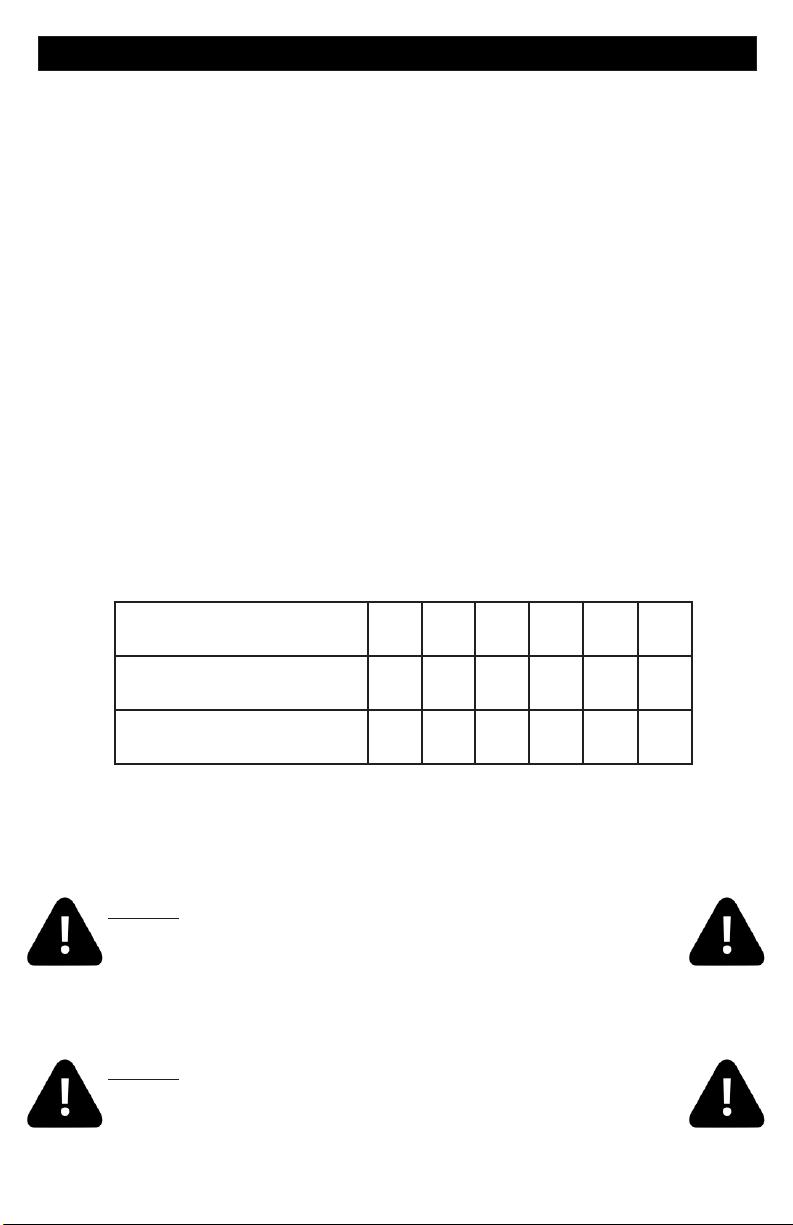
ELECTRICAL CONNECTIONS
OPTION 1
20-60AMP HARDWIRED
MAIN BREAKER PANEL
LINE 1
N
LINE 2
Option 1 shows the power from GFCI breaker installed into main service panel to a
service disconnect within line-of-site of the spa. If the manufacturer of your homes main
breaker panel makes a GFCI breaker, you may be able to add it to an open slot in the
panel.
GFCI Installed in Main Service Panel
INLINE SPA DISCONNECT
PORTABLE SPA
REFER TO GFCI WIRING DETAIL ON PAGE 8
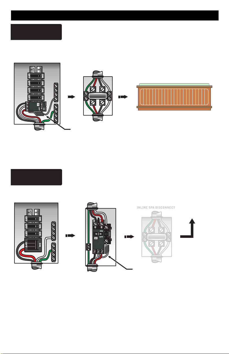
OPTION 2
20-60AMP HARDWIRED
MAIN BREAKER PANEL
Subpanel GFCI Installed
GFCI DISCONNECT
INLINE SPA DISCONNECT
TO PORTABLE SPA
LINE 1NLINE 2
REFER TO GFCI WIRING DETAIL ON PAGE 8
Option 2 shows the power from main service panel to a GFCI subpanel within line-of-site
of the spa. (Note: Most local codes will allow a GFCI subpanel to be a disconnect. If this is
not the case in your installation, a disconnect must be provided.)
6
Electrical Installation
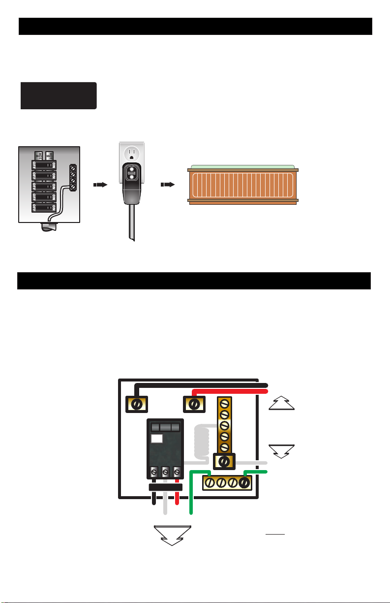
If your system was configured to include a 120VAC power cord, ensure that the proper
receptacle has been installed (a dedicated circuit is required). DO NOT under any
circumstances modify a 20 Amp plug to fit into a 15 Amp receptacle or use an extension
cord. Doing so will create hazardous conditions and/or invalidate the warranty.
OPTION 3
15/20AMP CORD END GFCI
MAIN BREAKER PANEL
Units with 15A / 20A GFCI Plug Connection
DEDICATED
15A / 120V OUTLET
PORTABLE SPA
This illustration depicts a typical 15 AMP, cord-end GFCI installation.
(The spa must be installed on a dedicated circuit.)
GFCI Wiring Detail
It is important that the GFCI circuit breaker is installed correctly. Often this
component has been improperly installed causing the breaker to instantly trip
when the system is turned on. Below is an illustration of a typical GFCI breaker
installation.
WARNING: Refer to the circuit breaker manufacturers installation
instructions. This illustration is meant to be a guide for Field Technicians
and is not intended to override or substitute the instructions supplied with
the circuit breaker.
LINE 1
LINE 2
LINE LUG #1
TEST
GFCI
(Ground Fault Circuit Interrupter)
CIRCUIT BREAKER
LOAD
LINE 1
NEUTRAL
TO SPA CONTROL SYSTEM
LINE LUG #2
LINE 2
GROUND
INCOMING
SERVICE
CONDUCTORS
FROM
MAIN
NEUTRAL PIGTAIL
GROUND BUS BAR
NEUTRAL BUS BAR
LOAD NEUTRAL MUST BE CONNECTED
DIRECTLY TO GFCI AS SHOWN
PANEL
NEUTRAL
GROUND
7
 Loading...