

HydroQuip 9700 Owner's Operation Manual
9700 SERIES
OWNERS OPERATION GUIDE
1 2
3


TABLE OF CONTENTS
Important Safety Instruction 2-3
Introduction 4
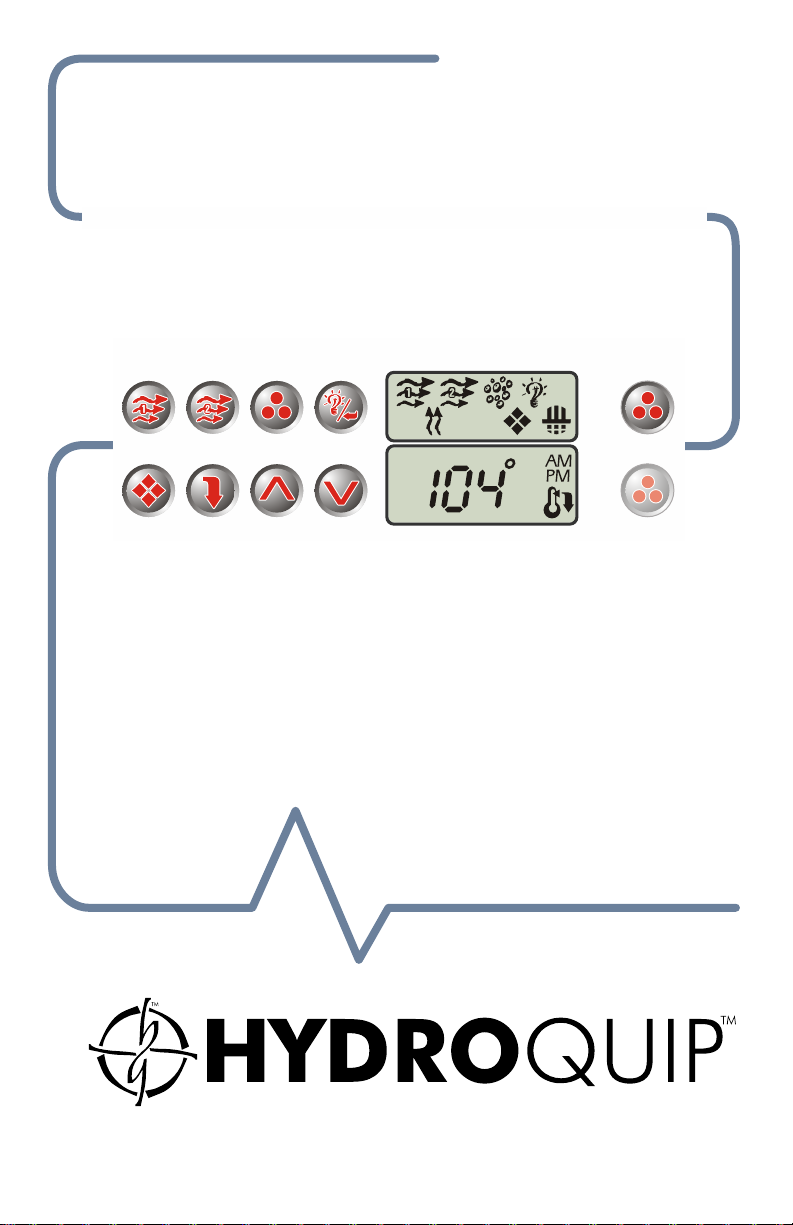
Features & Functions 5
.......................................................................
......................................................
Visual Diagnostic System 6-7
Electrical Installation 8
.......................................................
Electrical Connections 9-10
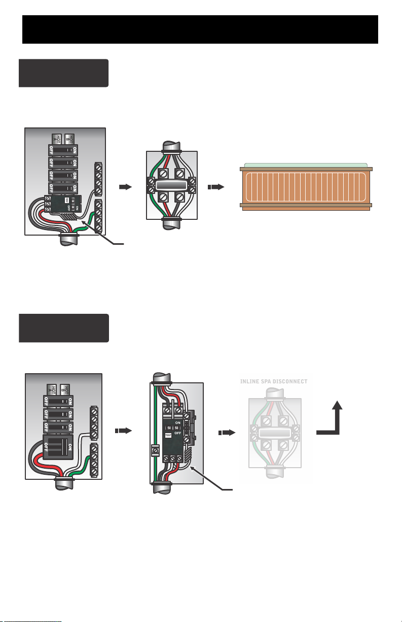
GFCI Wiring Detail 11
..........................................................
Incoming Power Wiring 12
Receptacle Guide 13
Heater Installation 14
............................................................
............................................................
Versi-Heat Considerations 15
Low-Flow System Configuration 16
Temp. Sensor Installation 17
Spa Light Installation 17
Spaside Installation 18
......................................................
.........................................................
Starting Up The System 19
Low Level Programming 20
Your Spaside Control 21-23
.................................................
Filter Cycle Programming 24
Economy Mode Programming 25
Error Indication 26-27
.................................................................
Operational Considerations 27-28
Troubleshooting 29-30
................................................................
Special Considerations 31
System Data Label 32
Warranty Information 33
Notes 34
.................................................................................
..........................................................
.......................................................
...........................................
...............................................
....................................................
...................................................
..............................................
....................................
...............................................
..................................................
.......................................................
...............................................
........................................
............................................
....................................................
1

IMPORTANT SAFETY INSTRUCTIONS
READ AND FOLLOW ALL INSTRUCTIONS
DANGER To reduce the risk of injury, do not permit children to use this product unless they are
!
closely supervised at all times.
WARNING - RISK OF CHILD DROWNING. Extreme caution must be exercised to prevent
!
unauthorized access by children. To avoid accidents, ensure that children cannot use a spa
or hot tub unless they are supervised at all times.
DANGER To reduce the risk of injury to persons, do not remove suction fittings.
!
Spa location must accommodate sufficient drainage of water around the base of the structure, as
well as the power source compartment.
Prolonged immersion in water that is warmer than normal body temperature can result in a
dangerous condition known as HYPERTHERMIA. The causes, symptoms, and effects of
hyperthermia may be described as follows: Hyperthermia occurs when the internal
temperature of the body reaches a level several degrees above the normal body
temperature of 98.6F. The symptoms of hyperthermia include dizziness, fainting,
drowsiness, lethargy, and an increase in the internal temperature of the body. The effects of
hyperthermia include (1) unawareness of impending hazard, (2) failure to perceive heat, (3)
failure to recognize the need to exit spa, (4) physical inability to exit spa, (5) fetal damage in
pregnant women, (6) unconsciousness resulting in danger of drowning. WARNING The
use of alcohol, drugs or medication can greatly increase the risk of fatal hyperthermia in hot
tubs and spas.
DANGER - RISK OF ELECTRICAL SHOCK. Install at least 5 feet (1.5m) from all metal surfaces.
!
(A spa may be installed within 5 feet of metal surfaces if each metal surface is permanently
connected by a solid copper conductor attached to the wire connector on the terminal box
that is provided for this purpose. Refer to NEC and local codes in effect at the time of
installation.)
A pressure wire connector is provided on the control box to permit connection of a solid copper
bonding conductor between this point and any equipment, metal enclosures of electrical
equipment, metal water pipe, or conduit within 5 feet (1.5m) of the unit as needed to comply
with local requirements.
Bond accessible metal to the dedicated connector on the equipment grounding bus, bond the
equipment ground bus to the local common bonding grid as part of the installation in the
form of (1) a reinforced concrete slab for support, (2) a ground plate provided beneath the
hot tub or spa, or (3) a permanent ground connection that is acceptable to the local
inspection authority.
DANGER RISK OF ELECTRICAL SHOCK. Do not permit any electrical appliance, such as a
!
light, telephone, radio, or television, within 5 feet (1.5m) of a spa or hot tub.
To reduce the risk of injury:
The water in a spa or hot tub should never exceed 104F (40C). Water temperatures between
100F (38C) and 104F (40C) are considered safe for a healthy adult. Lower water
temperatures are recommended for extended use (exceeding 10-15 minutes) and for young
children.
Excessive water temperatures have a high potential for causing fetal damage during the early
months of pregnancy, pregnant or possibly pregnant women should limit spa or hot tub
water temperatures to 100F(38C).
2

Before entering the spa or hot tub, the user should measure the water temperature with an
accurate thermometer.
The use of alcohol, drugs, or medication before or during spa or hot tub use may lead to
unconsciousness with the possibility of drowning.
Persons suffering from obesity or with a medical history of heart disease, low or high blood
pressure, circulatory system problems, or diabetes should consult a physician before using
a spa or hot tub.
Persons using medication should consult a physician before using a spa or hot tub since some
medication may affect heart rate, blood pressure, and circulation.
For Units with a GFCI (Ground Fault Circuit Interrupter)
This appliance is provided with a ground-fault-circuit-interrupter located on the control box.
Before each use and with the unit operating, push the test button. The unit should stop
operating and the reset button should appear. Push the reset button. The unit should now
operate normally. If the interrupter does not perform in this manner, a ground current is
flowing indicating the possibility of electrical shock. Disconnect the power, or unplug from
receptacle, until the fault has been identified and corrected.
For Cord and Plug Connected Units
Connected to a grounded, grounding type receptacle only. NEVER connect the spa to an
extension cord.
Do not bury the cord.
WARNING To reduce the risk of electrical shock, replace damaged cord immediately.
For Permanently Installed Units
A terminal marked “G” or “ground” is provided in the wiring box located inside the equipment
compartment. To reduce the risk of electric shock, connect the terminal or connector to the
grounding terminal of your electrical service or supply panel with a continuous green
insulated copper wire in accordance with National Electric Code Table 250-95 and any other
local codes in effect at the time of the installation.
For Permanently Installed Units not Provided with an Internal Disconnecting Method
The electrical supply for this product must include a suitably rated switch or circuit breaker to
open all ungrounded supply conductors to comply with Section 422-30 of the National
Electric Code, ANSI/NFPA 70 1987. The disconnecting means must be readily accessible to
the tub occupant but installed at least 5 feet (1.5m) from the tub water.
For Units with Gas Heaters
WARNING - Do not install indoors. This unit uses a gas heater that requires proper ventilation
and is intended for outdoor use only.
For UL Listed Equipment Assemblies
Install at least 5 feet (1.5m) from tub water using nonmetallic plumbing. Install blower no less
than 1 foot (305mm) above the maximum water level to prevent water from contacting
electrical equipment. Install in accordance with the installation instructions.
To reduce the risk of drowning from hair and body entrapment, install a suction fitting(s) with a
marked flow rate in gallons-per-minute that equals or exceeds the flow rate marked on the
equipment assembly.
3
INTRODUCTION
Congratulations on your new purchase. This Equipment or Control System is
constructed of the finest materials and assembled under the strictest quality control
standards. With proper care and maintenance your system will provide you with many
years of reliable performance.
The following pages contain information concerning the operation and care of your
system.
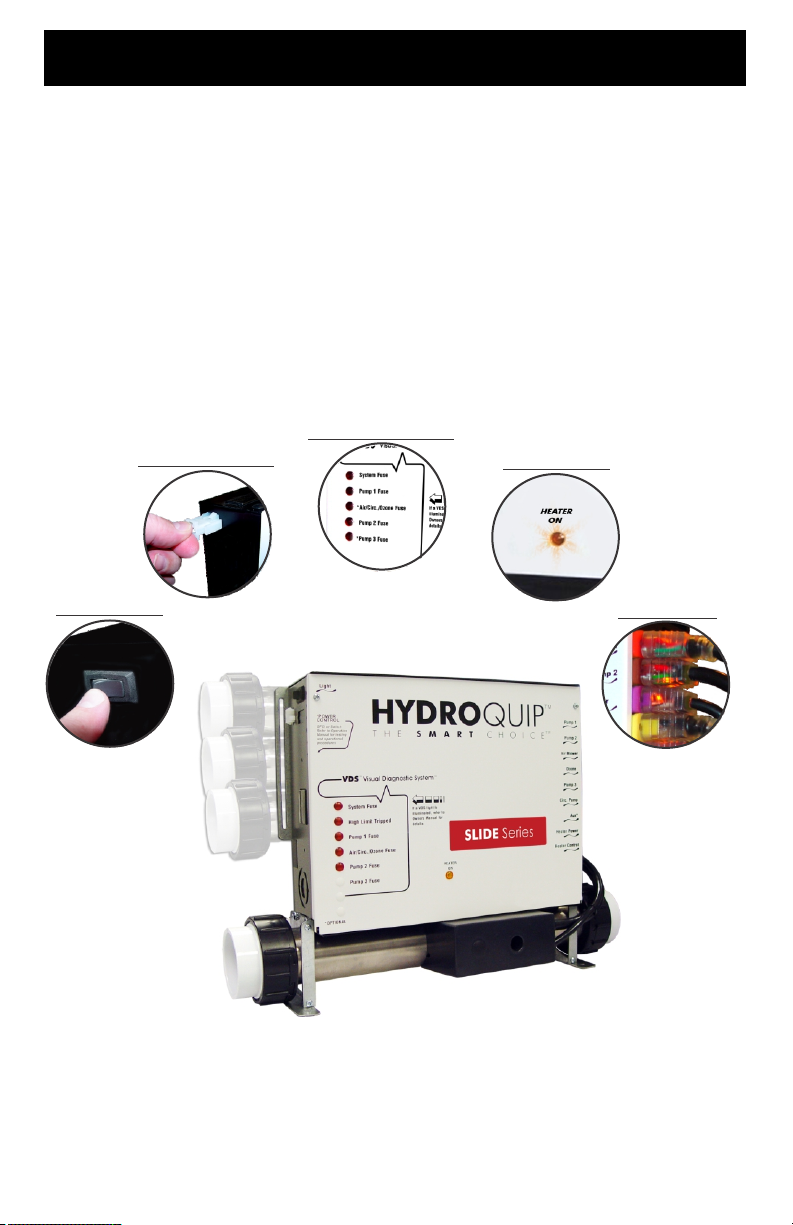
VISUAL DIAGNOSTICS
LIGHT CONNECTION
HEATER ACTIVE
POWER SWITCH
SMART CORDS
Note: Your system may differ from the photos above although the basic operation and
configuration will be the same.
4

FEATURES & FUNCTIONS
POWER SWITCH
Your system may have come equipped with a power
switch. This switch will turn power to the internal
circuitry & attached components on and off.
HEATER ON INDICATOR
All systems are equipped with a “Heater On” indicator
to let the user know when the heater is actively heating
the spa water.
SMART CORDS
Your system may have come equipped with exclusive
“Smart Cords”. These cords have internal illumination
to let you know that power is being supplied to the
components connected to them. This is a helpful
troubleshooting feature should a problem with a
component arise.
5
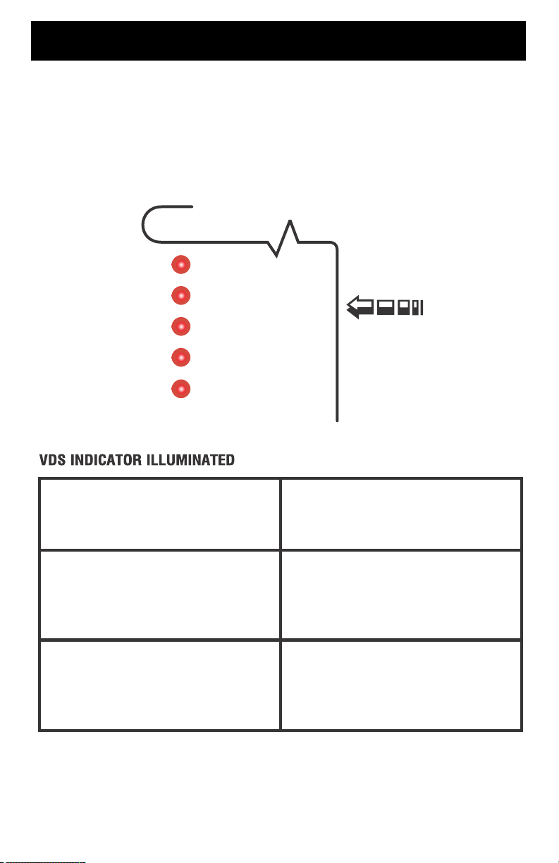
VISUAL DIAGNOSTIC SYSTEM
If your system is equipped the Visual Diagnostic System, the control will do the
troubleshooting for you! VDS consists of control mounted indicators and (if equipped)
exclusive “Smart Cords”. You will know at a glance if components are being supplied
with proper voltage or if an internal fuse has blown.
VDS
System Fuse
Pump 1 Fuse
*Air/Circ./Ozone Fuse
Pump 2 Fuse
*Pump 3 Fuse
SYSTEM FUSE - This fuse protects
the printed circuit board.
PUMP 1 FUSE - Protects the primary
pump.
Visual Diagnostic System
If a VDS light is
illuminated, refer to
Owners Manual for
details
Input voltage connected incorrectly.
Call your local dealer or qualified
technician.
Restricted flow of water, faulty pump
or severe weather/electrical storm.
Call your local dealer or qualified
technician.
AIR/CIRC./OZONE FUSE - Protects
the air blower/circulation pump &
ozonator.
Restricted flow of water, faulty pump/
air blower/ozonator or severe weather/
electrical storm. Call your local dealer
or qualified technician.
6

VISUAL DIAGNOSTIC SYSTEM (Cont.)
Restricted flow of water, faulty pump
PUMP 2 FUSE - Protects the second
pump.
PUMP 3 FUSE - Protects the third
pump.
Your particular system may not include all of the components listed. If a component
continually blows the fuse, that component may be defective. Call you local spa
dealer or qualified technician.
or severe weather/electrical storm.
Call your local dealer or qualified
technician.
Restricted flow of water, faulty pump
or severe weather/electrical storm.
Call your local dealer or qualified
technician.
7

ELECTRICAL INSTALLATION
A qualified and licensed electrician in accordance with the National Electric Code (NEC)
Article 680, Canadian Electric Code, and with any local codes must accomplish the
electrical installation.
All connections must be made according to the electrical installation label on the outside
of the control box (see page 33). Follow the instructions from the label if they are different
than the instructions in this manual. If your electrician is not absolutely sure how to
connect your system correctly, call your local dealer. Any mistake may be costly and void
your equipment warranty.
The GFCI (Ground Fault Circuit Interrupter) is a mandatory electrical safety device
required for all portable spas and hot tubs as specified in the National Electrical Code
Article 680-42. The GFCI in your particular installation may be installed at the
electrical service panel, a separate sub-panel or built into your Hydro-Quip System.
Your spa equipment requires a DEDICATED CIRCUIT. No other appliances or lights
can be on this circuit. Refer to equipment data label for power supply requirements of
your spa equipment.
Use copper conductors ONLY. The ground must be sized following the National
Electric Code, Table 250-95.
For Power conductor size, refer to the National Electric Code Table 310-16.
NOTE: Due to the electrical requirements of some models, it may be required to
SPLIT the incoming electrical service to accommodate the GFCI Circuit Breaker
limits. Contact your electrician if you need additional information on this topic.
Circuit & Breaker
Rating
Maximum Amps
Minimum Wire
Size
Universal Systems require a Neutral wire therefore the service required is as follows:
120-volt systems require a three-wire electrical service including ground, consisting of
Line 1 (Black), Neutral (White) and Ground (Green). 240-volt systems require a four
wire electrical service including ground, consisting of Line 1 (Black), Line 2 (Red),
Neutral (White) and Ground (Green).
15A 20A 30A 40A 50A 60A 70A 80A
12A
16A 24A
14 12 10
32A 40A 48A 56A 64A
8
6 4
4
4
8
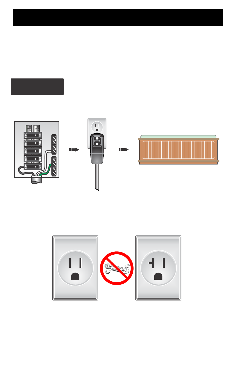
ELECTRICAL CONNECTIONS
If your system was configured to include a 120VAC power cord, ensure that the
proper receptacle has been installed (a dedicated circuit is required). DO NOT under
any circumstances modify a 20 Amp plug to fit into a 15 Amp receptacle or use an
extension cord. Doing so will create hazardous conditions and/or void the warranty.
OPTION 1
15/20AMP CORDEND GFCI
MAIN BREAKER PANEL
Units with 15A GFCI Plug Connection
DEDICATED
15A/120V OUTLET
PORTABLE SPA
This illustration depicts a typical 15/20 AMP, cord-end GFCI
installation.
(The spa must be installed on a dedicated circuit.)
15 AMP
RECEPTACLE
DO NOT
USE AN
EXTENSION
CORD
9
20 AMP
RECEPTACLE
ELECTRICAL CONNECTIONS
OPTION 2
20-60AMP HARDWIRED
MAIN BREAKER PANEL
LINE 1
N
LINE 2
GFCI Installed in Main Service Panel
INLINE SPA DISCONNECT
PORTABLE SPA
REFER TO GFCI WIRING DETAIL ON PAGE 8
Option 1 shows the power from GFCI breaker installed into main service panel to a
service disconnect within line-of-site of the spa. If the manufacturer of your homes main
breaker panel makes a GFCI breaker, you may be able to add it to an open slot in the
panel.
OPTION 3
20-60AMP HARDWIRED
MAIN BREAKER PANEL
Subpanel GFCI Installed
GFCI DISCONNECT
INLINE SPA DISCONNECT
TO PORTABLE SPA
LINE 1NLINE 2
REFER TO GFCI WIRING DETAIL ON PAGE 8
Option 2 shows the power from main service panel to a GFCI subpanel within line-of-site
of the spa. (Note: Most local codes will allow a GFCI subpanel to be a disconnect. If this is
not the case in your installation, a disconnect must be provided.)
10
 Loading...