

Page 1

Ethernet Adapter
User Guide
Hydronix Part no: HD0333
Version: 2.0.0
Revision date: January 2008
Page 2

2
Ethernet Adapter User Guide
HD0333 Issue 2.0.0
COPYRIGHT
Neither the whole or any part of the information containe d in nor the product described in this documentation may b e
adapted or reproduced in any material form except with the prior written approval of Hydronix Limited, hereinafter
referred to as Hydronix.
© 2008
Hydronix Limited
7 Riverside Business Centre
Walnut Tree Close
Guildford
Surrey
GU1 4UG
United Kingdom
All rights reserved
CUSTOMER RESPONSIBILITY
The customer in applying the product described in this documentation accepts that the product is a programmable
electronic system which is inherently complex and which may not be completely free of errors. In doing so the customer
therefore undertakes responsibility to ensure that the product is properly installed commissioned operated and
maintained by competent and suitably trained persons and in accordanc e with any instructions or safety precautions
made available or good engineering practice and to thoroughly verify the use of the prod uct in the particular application.
ERRORS IN DOCUMENTATION
The product described in this documentation is subject to continuous development and improvement. All information of a
technical nature and particulars of the product and its use i ncluding the information and particulars contained in this
documentation are given by Hydronix in good faith.
Hydronix welcomes comments and suggestions relating to the product and this documentation
ACKNOWLEDGEMENTS
Hydronix, Hydro-Probe, Hydro-Mix, Hydro-View and Hydro-Control are Registered Trade Marks of H ydro nix Limited
Page 3

3
Ethernet Adapter User Guide
HD0333 Issue 2.0.0
Revision history
Revision No. Date Description of change
1.0.0 December 2007 First Draft
2.0.0 January 2008 First edition released
Page 4

4
Ethernet Adapter User Guide
HD0333 Issue 2.0.0
Table of Contents
Chapter 1 Introduction ..........................................................................................................................7
Kit Contents.......................................................................................................................................8
Chapter 2 Connecting with Sensors .....................................................................................................9
Installation.............................................................................................................................................9
Ethernet Adapter Only (EA01)...........................................................................................................9
Power over Ethernet (EPK01).........................................................................................................10
Connections........................................................................................................................................11
Wiring Connections.........................................................................................................................11
RS-485 Wiring Recommendations..................................................................................................12
Indicator Lights ...................................................................................................................................13
Chapter 3 Connecting with Hydro-Control V.......................................................................................15
Introduction.........................................................................................................................................15
Installation...........................................................................................................................................15
Ethernet Adapter Only.....................................................................................................................15
Power over Ethernet (EPK01).........................................................................................................16
Connecting with Hydro-Control V........................................................................................................17
Programming......................................................................................................................................17
Chapter 4 Configuring the Ethernet Adapter.......................................................................................19
Ethernet Adapter defaults...................................................................................................................19
Finding an Ethernet Adapter automatically.........................................................................................19
Adding an Ethernet Adapter manually ................................................................................................20
Changing the Ethernet Adapter IP Address........................................................................................21
Remote (Internet) Connection.............................................................................................................21
Chapter 5 Technical Specifications ....................................................................................................23
EA01 Ethernet Adapter.......................................................................................................................23
EPA01 Ethernet Power Adapter .........................................................................................................23
EPI01 Ethernet Power Injector............................................................................................................23
Terminal Identification.........................................................................................................................24
Chapter 6 Fault Finding ......................................................................................................................27
Ethernet Adapter EA01.......................................................................................................................27
Ethernet Power Adapter EPA01 .........................................................................................................27
Ethernet Power Injector EPI01............................................................................................................28
Page 5

5
Ethernet Adapter User Guide
HD0333 Issue 2.0.0
Table of Figures
Figure 1: Ethernet Adapter Kit Connections.............................................................................................7
Figure 2: Connections for Ethernet Adapter only......................................................................................9
Figure 3: Connections for Ethernet Adapter and Power Adapter............................................................10
Figure 4: Maximum number of sensor connections................................................................................11
Figure 5: Connecting the Ethernet Adapter to Hydro-Control V..............................................................15
Figure 6: EA01 Terminal Identification ...................................................................................................24
Figure 7: EPA01 Terminal Identification.................................................................................................25
Page 6

6
Ethernet Adapter User Guide
HD0333 Issue 2.0.0
Page 7
7
Ethernet Adapter User Guide
HD0333 Issue 2.0.0
Chapter 1 Introduction
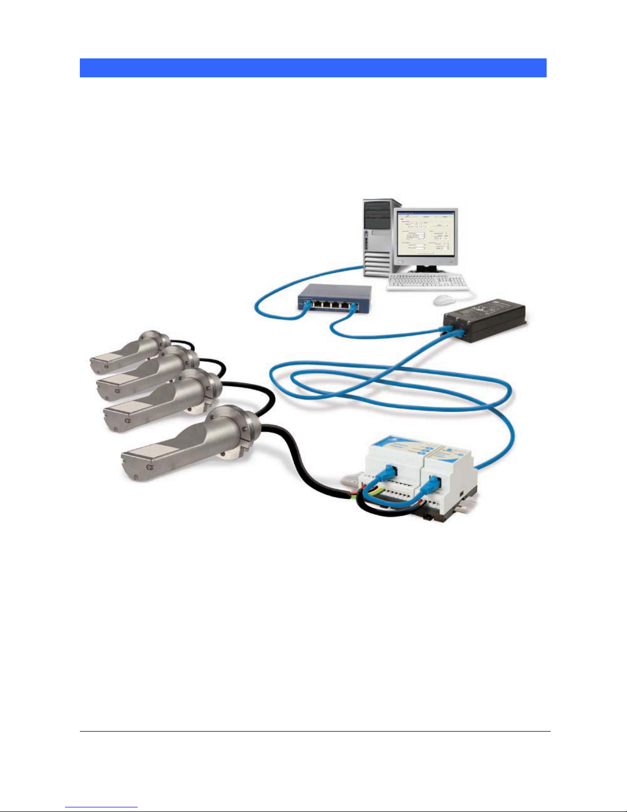
The Hydronix Ethernet Adapter provides a simple method of network enabl ing Hydronix products. The
Adapter is a small DIN-rail mounted unit that converts packets received over an Ethernet (TCP/IP)
network to RS485 or RS232. This enables a host PC elsewhere on the network to communicate with
sensors using Hydronix Hydro-Com software. Remote configuration and control of a Hydro-Control V
unit is also possible.
An option of using Power over Ethernet is available via a second small DIN-rail module to eliminate the
need for a local 24V supply for the sensors.
Figure 1: Ethernet Adapter Kit Connections
Page 8
Chapter 1 Introduction
8
Ethernet Adapter User Guide
HD0333 Issue 2.0.0
Kit Contents
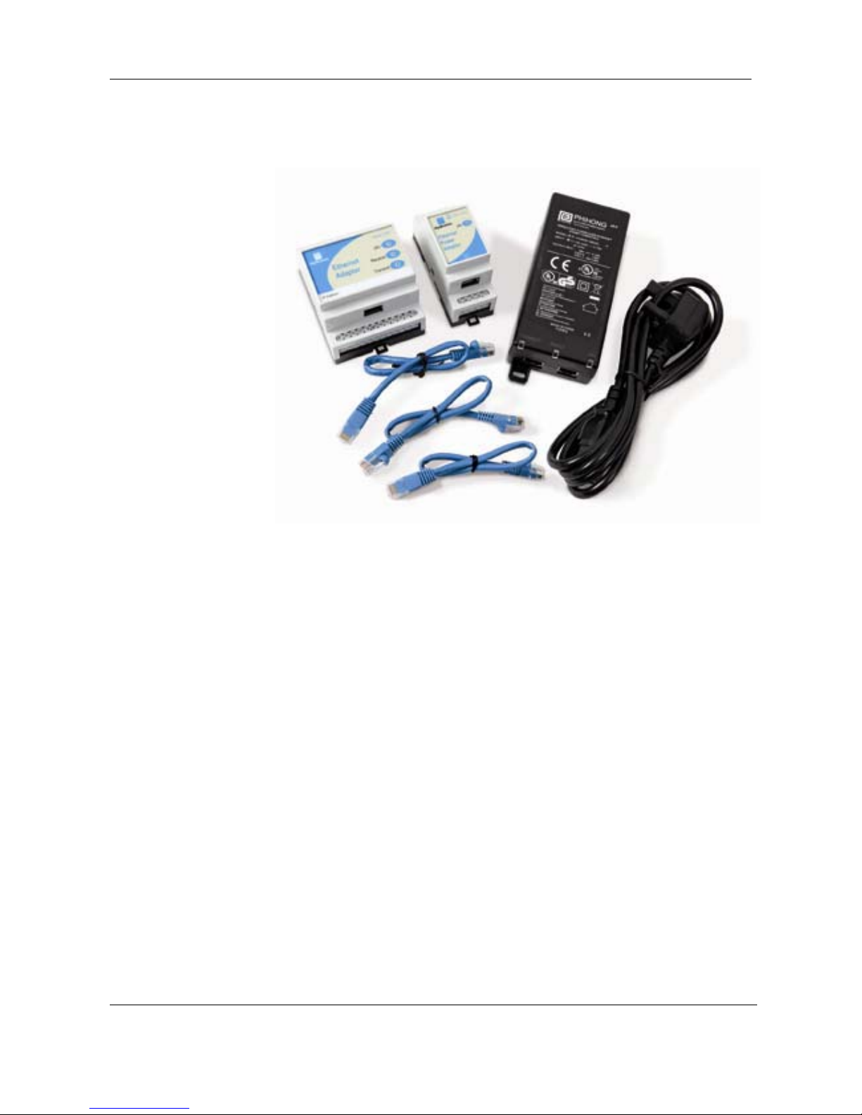
A – Ethernet Adapter – EA01
B – Ethernet Power Adapter – EPA01
C – Ethernet Power Injector – EPI01
D – IEC Mains Cable
E – Ethernet Patch Cables x 3
Order Options:
Ethernet Adapter Kit Part Number: EAK01
Comprises: Ethernet Adapter, Ethernet Patch Cable (0.5m), User Guide, CD with
Hydro-Com software and User Guide
Use: Use with external 24V power supply
Ethernet Power Adapter Kit: Part Number: EPK01
Comprises: All the above plus Ethernet Power Adapter, Power Injector, IEC
mains cable and 2 additional Ethernet Patch Cables
Use: Provides power and Ethernet connection over standard CAT5e cable
A
B
C
D
E
Page 9
9
Ethernet Adapter User Guide
HD0333 Issue 2.0.0
Chapter 2 Connecting with Sensors
Installation
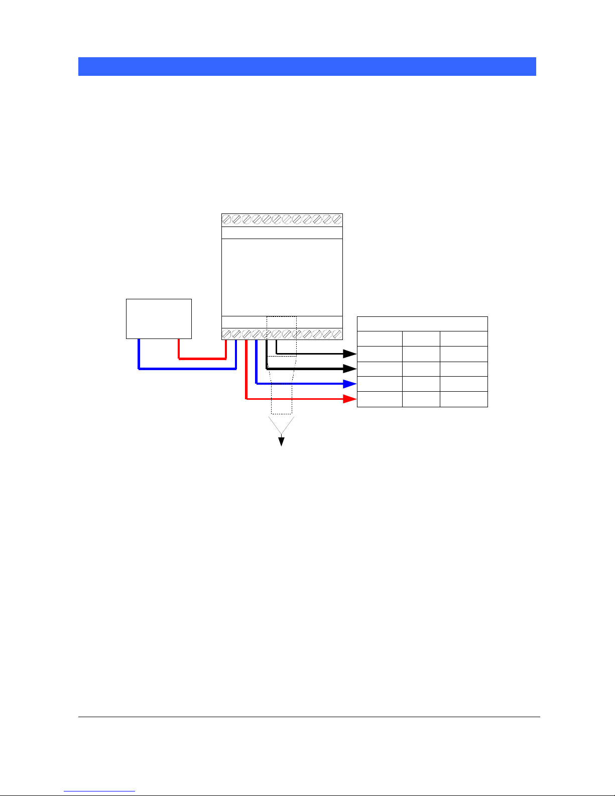
Depending on the installation option chosen, the system should be set up as shown in the diagrams
below. Terminal identification for each module is shown later in this chapter.
Ethernet Adapter Only (EA01)
The most basic setup uses only the Ethernet Adapter and is arranged as shown below:
Cable T o Sensor
Black
RS/485 A
RS/485 B
0v DC
24v DC
Colour
White
Black
Red
MILSPEC
F
G
B
A
EA01
Ethernet
Adapter
1
24v DC
Powe r Sup ply
0v 24v
10/100baseT
CAT5e
Ethernet
to network
Figure 2: Connections for Ethernet Adapter only
Location of the Ethernet Adapter (EA01)
The Ethernet Adapter should be mounted in the wiring junction box as close to the sensors as
possible, and protected from water and excessive dust. Connect the Ethernet drop cable from
the network connection to the Ethernet port of the Adapter. Connect a 24V dc supply to the
24V+ and 0V input terminals of the Ethernet Adapter, ensuring that the power supply and wire
is of a sufficient power rating to carry the power for the number of sensors connected.
Connect the RS485 sensor cable to the Ethernet Adapter outputs, taking care to note the
recommendations in the RS485 Wiring Recommendations in Chapter 3.
Page 10
Chapter 2 Connecting with Sensors
10
Ethernet Adapter User Guide
HD0333 Issue 2.0.0
Power over Ethernet (EPK01)
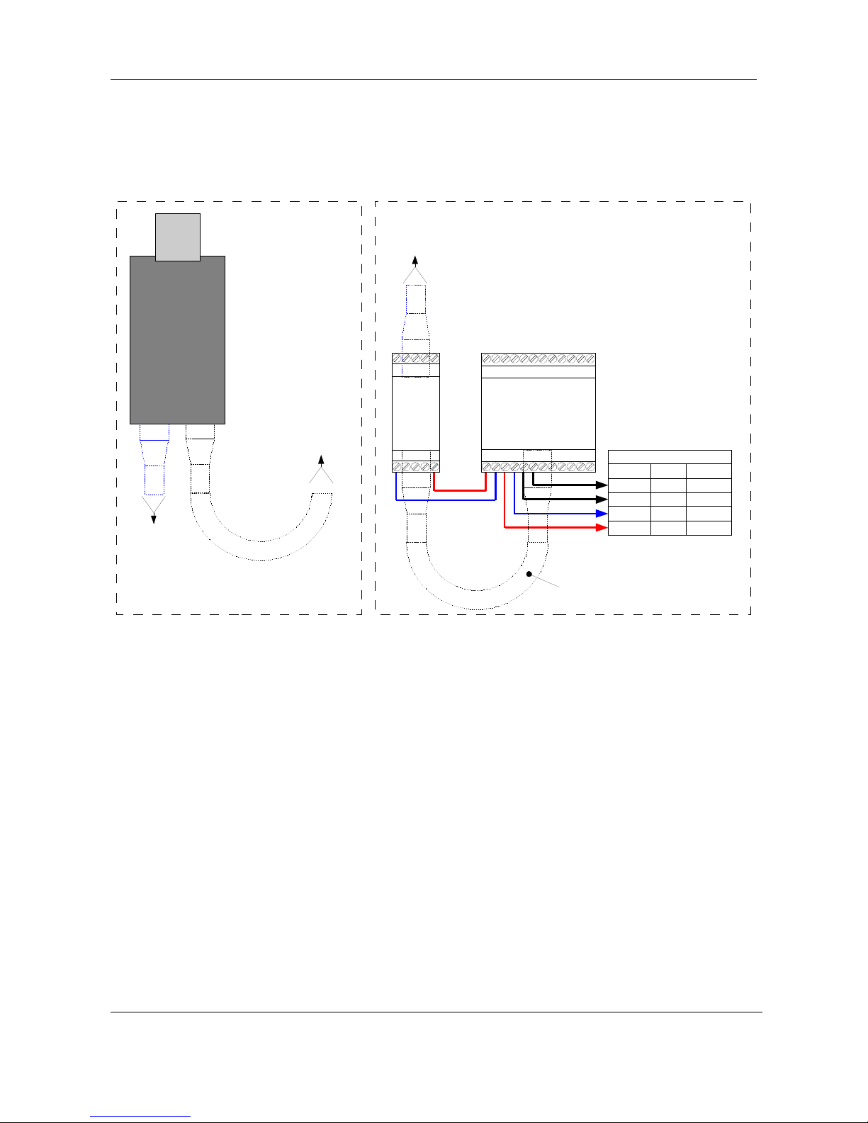
To eliminate the need for a local 24V supply for the adapter and sensors, the optional Power over
Ethernet kit can be used. The arrangement is as shown below:
Junction box close to sensorsControl Room Cabinet
Cable To Sensor
Black
RS/485 A
RS/485 B
0v DC
24v DC
Colour
White
Black
Red
MILSPEC
F
G
B
A
EPA01
Ethernet
Power
Adapter
1
EA01
Ethernet
Adapter
1
10/100baseT
CAT5e
linking
EPA01 and
EA01
EPI01
Ethernet
Power
Injector
OUT IN
IEC Mains
Cable
100-240v
50-60Hz
10/100baseT
CAT5e
Ethernet
to EPI01
10/100baseT
CAT5e
Ethernet
to EP A0 1
10/100baseT
CAT5e
Ethernet
to Network
Figure 3: Connections for Ethernet Adapter and Power Adapter
Location of the Power Adapter (EPA01)
The Power Adapter Module (EPA01) should be mounted in the wiring junction box close to the
sensors and beside the Ethernet Adapter, protected from water and excessive dust. Connect
the Ethernet drop cable from the router to the IN port of the Power Adapter. This cable carries
both the power and the Ethernet communications signals. Connect a short Ethernet cable from
the OUT port of the Power Adapter to the Ethernet port on the Adapter. This cable carries only
the Ethernet communications. Connect short insulated wires from the 24V+ and 0V outputs of
the Power Adapter to the 24V+ and 0V inputs of the Ethernet Adapter, ensuring that the wire is
of sufficient power rating to carry the power for the number of sensors connected.
Connect the RS485 sensor cable to the Ethernet Adapter outputs, taking care to note the
recommendations in the RS485 Wiring Recommendations in Chapter 3.
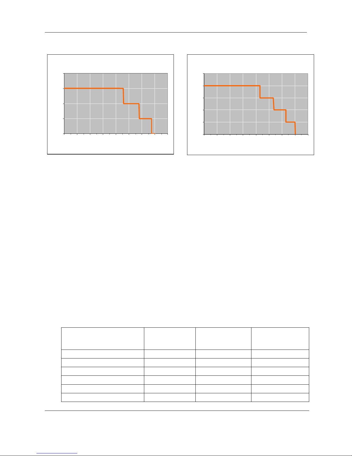
Sufficient ventilation and cooling should be employed to keep the air temperature around the
unit to a suitable level for the number of sensors being powered. The diagram below shows
the number of sensors that can be used at different air temperatures for each sensor type.
Page 11
Connecting with Sensors Chapter 2
11
Ethernet Adapter User Guide
HD0333 Issue 2.0.0
Figure 4: Maximum number of sensor connections
NOTE: Operation above these limits may cause premature failure of the unit.
Location of the Power Injector Module (EPI01)
The Power Injector Module (EPI01) should ideally be located in the computer room or network
cabinet close to the router. Identify which drop cable runs to the sensor location, and using a
short patch cable insert the Power Injector into that cable, connecting the port labelled IN to
the router output and the port labelled OUT to the drop cable. Connect a 240V or 110V mains
supply to the Power Injector.
Note: The Power Injector Module can supply sufficient power for up to four Hydronix HydroProbe II sensors or three Hydro-Mix VI, Hydro-Probe Orbiter or Hydro-Probe SE (Hydrotrac)
sensors. If more sensors are to be connected to the network, then a separate power supply
local to the sensors should be used instead of the Power over Ethernet solution.
Connections
Wiring Connections
Ethernet Adapter sensor connections:
Ethernet Adapter Terminal
Signal
Description
MIL Spec pin
number on sensor
Wire Colour in
standard Hydronix
0090A cable
1 24V + input
2 0V input
3 24V + to sensor A Red
4 0V to sensor B Black
5 RS485 B G Black
6 RS485 A F White
HydroMix / Orbite r / HydroProbe S E
0
1
2
3
4
0 1020304050607080
Maxim um Air Temperature
Number of Sensors
HydroProbe II
0
1
2
3
4
5
0 1020304050607080
Maximum Air Temperature
Number of Sensors
Page 12

Chapter 2 Connecting with Sensors
12
Ethernet Adapter User Guide
HD0333 Issue 2.0.0
The white and black are from one twisted pair and the red and black from another.
Ethernet Power Adapter connections:
Ethernet Power Adapter Terminal Signal Description
1 0V output
5 24V + output
RS-485 Wiring Recommendations
The performance and reliability of a RS485 network can depend significantly on the quality and
design of the wiring used. It is recommended to use 24AWG twisted pairs with a characteristic
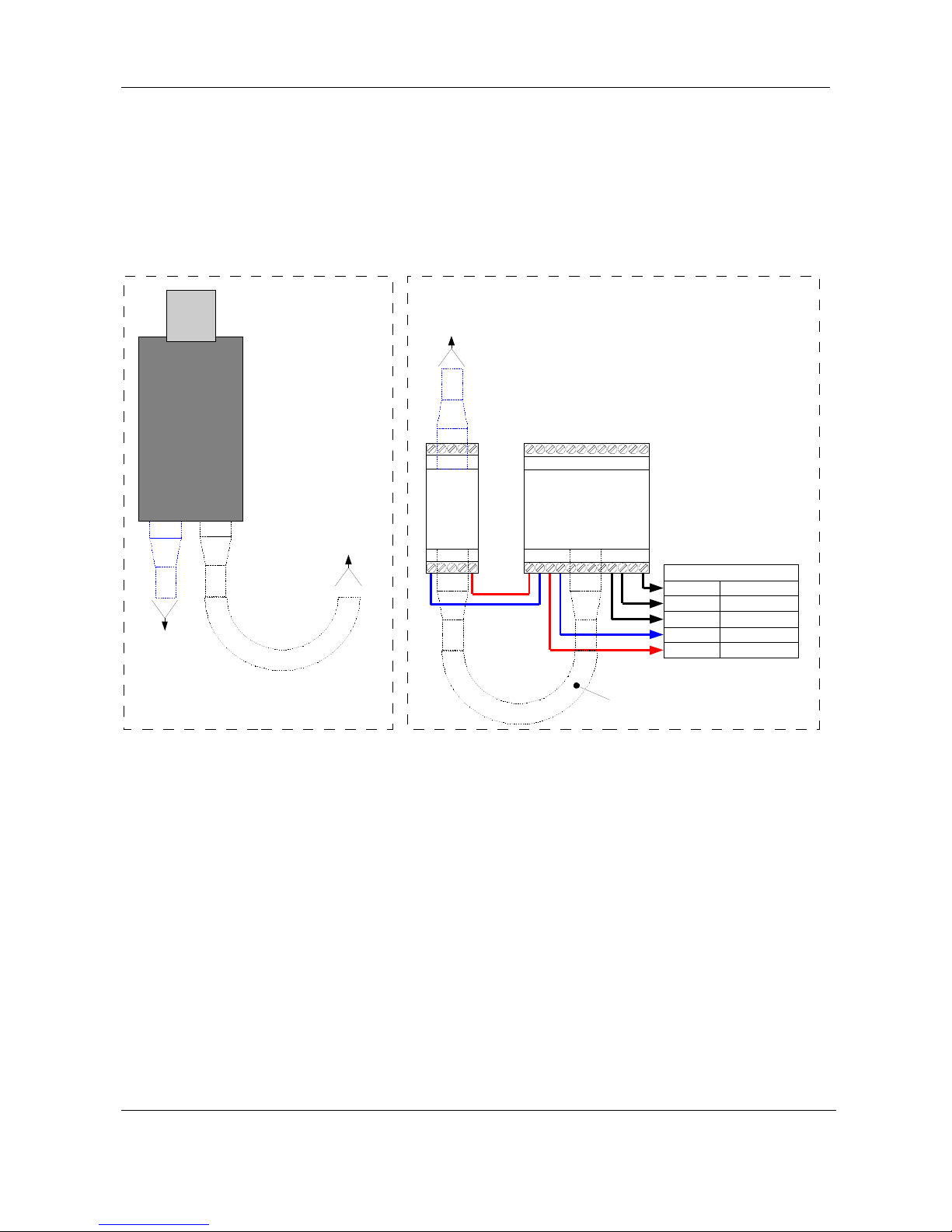
impedance (Zo) of 100R – 120R. Ideally, sensors on a RS485 network should be connected in a
daisy chain arrangement, as shown here:
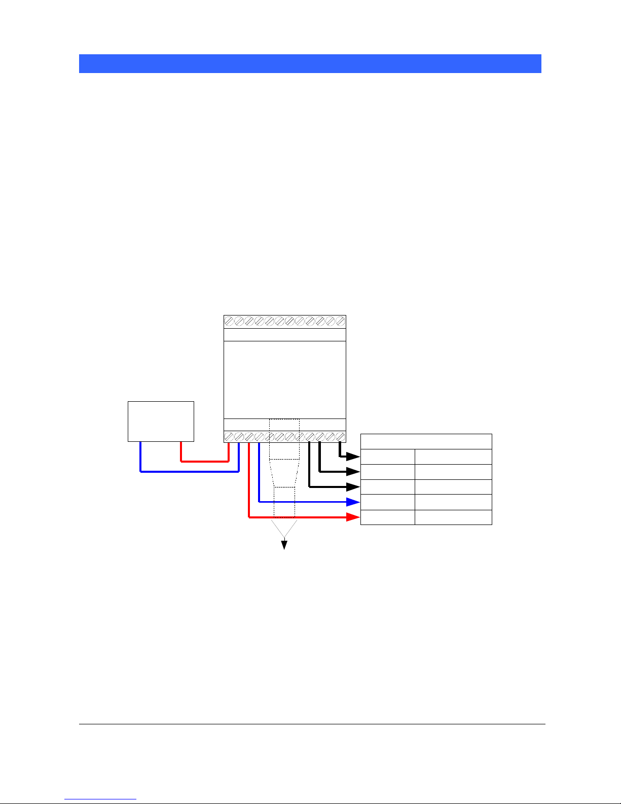
This arrangement uses just one of the sets of sensor outputs on the Ethernet Adapter. In practice,
this arrangement is hard to achieve, so sensors may be wired using very short stubs:
Although the Ethernet Adapter has multiple sets of sensor outputs, wiring in a star configuration
with each sensor wired to an output set should be avoided if at all possible.
Page 13

Connecting with Sensors Chapter 2
13
Ethernet Adapter User Guide
HD0333 Issue 2.0.0
Indicator Lights
The Ethernet Power Adapter unit (EPA01) has a single red indicator light on the top, which indicates that
it is supplying power. It must be connected to an Ethernet cable with a 802.11af compliant Power Injector
supplying it.
The Ethernet Adapter (EA01) has three indicator lights on the top. The red
indicator illuminates when a suitable 24V supply is connected. The transmit
indicator light blinks when data is received by the Adapter and is being sent to
the sensors. The receive indicator light blinks when data is received from the
sensors and is being sent over the Ethernet to the host system.
Additionally, the green indicator light above
the network connector indicates that a network
connection has been established, and the
yellow indicator blinks when network data is
sent or received
Page 14

Chapter 2 Connecting with Sensors
14
Ethernet Adapter User Guide
HD0333 Issue 2.0.0
Page 15
15
Ethernet Adapter User Guide
HD0333 Issue 2.0.0
Chapter 3 Connecting with Hydro-Control V
Introduction
The serial port of a Hydro-Control V unit may be connected to the RS232 port of an Ethernet Adapter to
allow remote access to recipe configuration and mix logs.
This cannot be done while an Adapter is communicating with sensors, as a different communications
protocol is used. Installation will be similar to one of the options described above, except that the RS232
Tx, Rx and GND signals will be connected to the Hydro-Control V unit.
Installation
Depending on the installation option chosen, the system should be set up as shown in the diagrams
below. Terminal identification for each module is shown later in this chapter.
Ethernet Adapter Only
The most basic setup uses only the Ethernet adapter and is arranged as shown below:
Black
Connections to HydroControl V
RS/23 2 Rx
RS/232 Tx
0v DC
24v DC
23
29
27
EA01
Ethernet
Adapter
1
21
22
RS/232 Gnd
24v DC
Powe r Sup ply
0v 24v
10/100baseT
CAT5e
Ethernet
to network
Figure 5: Connecting the Ethernet Adapter to Hydro-Control V
Location of the Ethernet Adapter (EA01)
The Ethernet Adapter should be mounted in the wiring junction box as close to the Hydro-Control
as possible, and protected from water and excessive dust. Connect the Ethernet drop cable from
the network connection to the Ethernet port of the Adapter. Connect a 24V dc supply to the 24V+
and 0V input terminals of the Ethernet Adapter,
Page 16
Chapter 3 Connecting with Hydro-Control V
16
Ethernet Adapter User Guide
HD0333 Issue 2.0.0
ensuring that the power supply and wire is of a sufficient power rating to carry the power for the
number of sensors connected.
Power over Ethernet (EPK01)
A single Hydro-Control V unit (with attached Hydro-Mix sensor) can be powered using the Power
over Ethernet kit. Connect one of the Sensor 24V and 0V connections to the Hydro-Control V
power input pins. The arrangement is as shown below:
Junction box close to Hydro-Control
Black
Connections to Hydro-Control V
RS/232 Rx
RS/232 Tx
0v DC
24v DC
23
29
27
21
22
RS/232 Gnd
Control Room Cabinet
EPA01
Ethernet
Power
Adapter
1
EA01
Ethernet
Adapter
1
10/100baseT
CAT5e
linking
EPA01 and
EA01
EPI01
Ethernet
Power
Injector
OUT IN
IEC Mains
Cable
100-240v
50-60Hz
10/100baseT
CAT5e
Ethernet
to EPI01
10/100baseT
CAT5e
Ethernet
to EP A0 1
10/100baseT
CAT5e
Ethernet
to Network
Figure 6: Connecting the Ethernet Adapter to Hydro-Control V with Power Over Ethernet Option
Location of the Power Adapter (EPA01)
The Power Adapter Module (EPA01) should be mounted in the wiring junction box with the
Hydro-Control and beside the Ethernet Adapter, protected from water and excessive dust.
Connect the Ethernet drop cable from the router to the IN port of the Power Adapter. This
cable carries both the power and the Ethernet communications signals. Connect a short
Ethernet cable from the OUT port of the Power Adapter to the Ethernet port on the Adapter.
This cable carries only the Ethernet communications. Connect short insulated wires from the
24V+ and 0V outputs of the Power Adapter to the 24V+ and 0V inputs of the Ethernet Adapter,
ensuring that the wire is of sufficient power rating to carry the power for the Hydro-Control V
and it’s sensor.
Connect RS232 cables between the Ethernet Adapter and the Hydro-Control V.
Page 17
Connecting with Hydro-Control V Chapter 3
17
Ethernet Adapter User Guide
HD0333 Issue 2.0.0
Location of the Power Injector Module (EPI01)
The Power Injector Module (EPI01) should ideally be located in the computer room or network
cabinet close to the router. Identify which drop cable runs to the Hydro-Control’s location, and
using a short patch cable insert the Power Injector into that cable, connecting the port labelled
IN to the router output and the port labelled OUT to the drop cable. Connect a 240V or 110V
mains supply to the Power Injector.
Note: The Power Injector Module can supply sufficient power for a Hydro-Control V and a
sensor attached to it.
Ethernet Adapter Hydro-Control V connections
Ethernet Adapter
Terminal
Signal Description Signal Function Hydro-Control V
Pin
3 24V + to sensor 24v to Hydro-Control V 27
4 0v to sensor 0v to Hydro-Control V 29
8 RS232 RTS RS232 Ready To Send Not used
9 RS232 Tx
Data from Ethernet Adapter to
Hydro-Control V
21
10 RS232 Rx
Data from Hydro-Control V to
Ethernet Adapter
22
11 RS232 CTS RS232 Clear To Send Not used
12 RS232 GND Ground connection 23
Connecting with Hydro-Control V
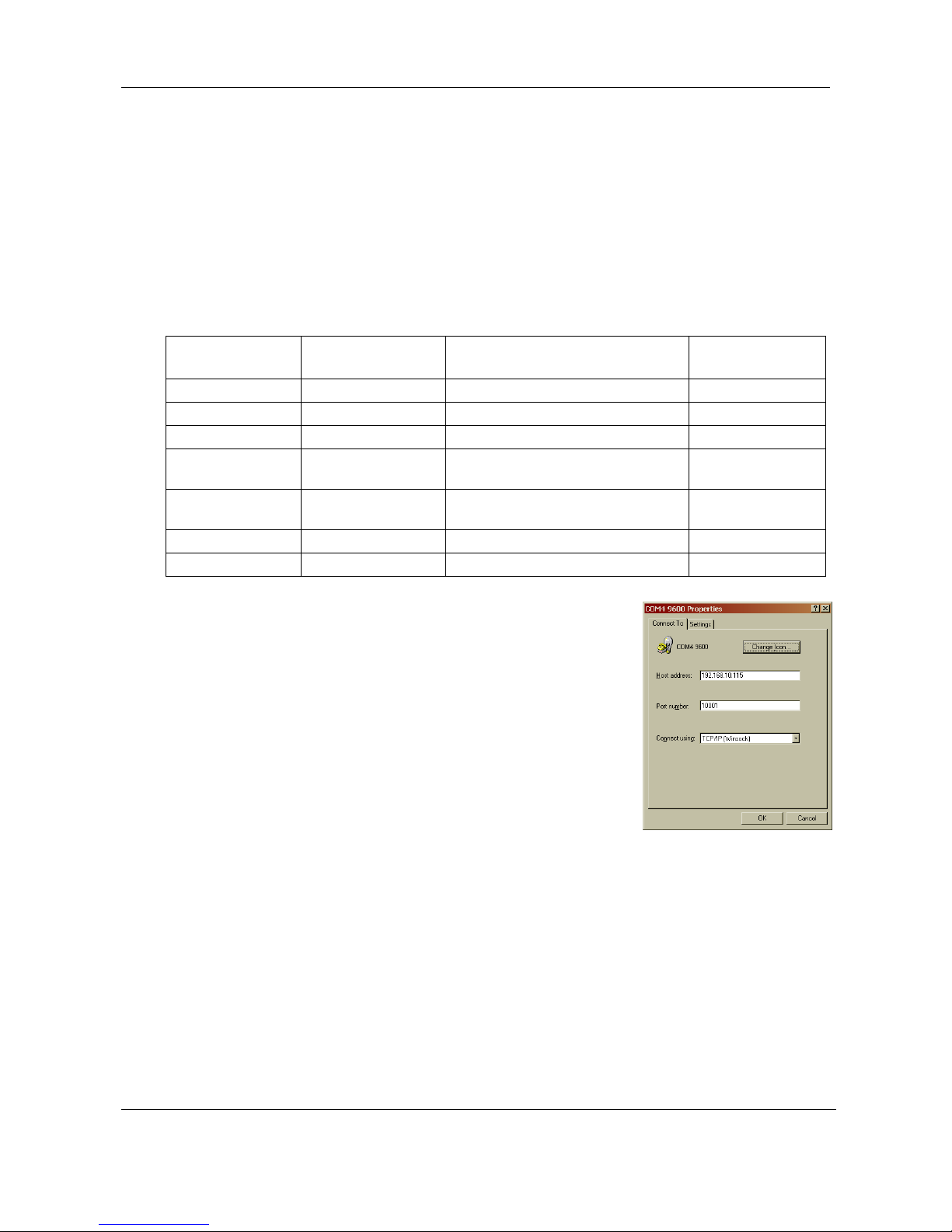
To communicate with a Hydro-Control V unit, start a terminal emulation
program such as HyperTerminal and set the connection properties as
shown, substituting the correct IP Address. Note specifically that the Port
number should be set to 10001.
The same “ * “ commands can be used as would normally be used over a
serial link, and the responses will provide the same information. Refer to
Chapter 4 of the Hydro-Control V Users Guide for more details of the
commands available.
Programming
An installation using the Ethernet Adapter packs the messages sent from a Host to the Sensor into an
Ethernet data packet, which is then unpacked by the Ethernet Adapter and converted into RS485 voltage
levels. If a custom application is being written to communicate with Hydronix sensors over the Ethernet,
then the Hydro-Link communications protocol should be implemented and the resulting message string
sent over the network to the Ethernet Adapter (instead of a serial port). In Visual Basic (VB6) this is done
using a WinSock control and in Visual Studio .NET this can either be done using a Sockets control or a
TCPClient control. A connection should be made from the Winsock or TCPClient control to port 10001 on
the Adapter. Further information on these controls can be found in the programming system
documentation, but please note that Hydronix are unable to provide technical support for developing
custom software applications
Page 18

Chapter 3 Connecting with Hydro-Control V
18
Ethernet Adapter User Guide
HD0333 Issue 2.0.0
Hydronix are currently developing a Class Library for .NET to implement all of the communications
functionality including support for the Ethernet Adapter, which will be available upon request. For details
of this and more information on the Hydro-Link Communications Protocol please contact Hydronix
Technical Support ([email protected]).
configuring the two Ethernet Adapters. Power for both units may optionally be provided over the Ethernet
cables, as described above
Page 19
19
Ethernet Adapter User Guide
HD0333 Issue 2.0.0
Chapter 4 Configuring the Ethernet Adapter
Ethernet Adapter defaults
By default, the Ethernet Adapter will use an automatically generated IP Address, which will be allocated
by the network DHCP server. As this may change after a few days or weeks, it is recommended that a
fixed IP Address is used for the Ethernet Adapter. The allocated address should be on the same subnet
as the address allocated by DHCP, but outside the range of DHCP addresses. Contact the Network
Administrator to find a suitable address.
Finding an Ethernet Adapter automatically
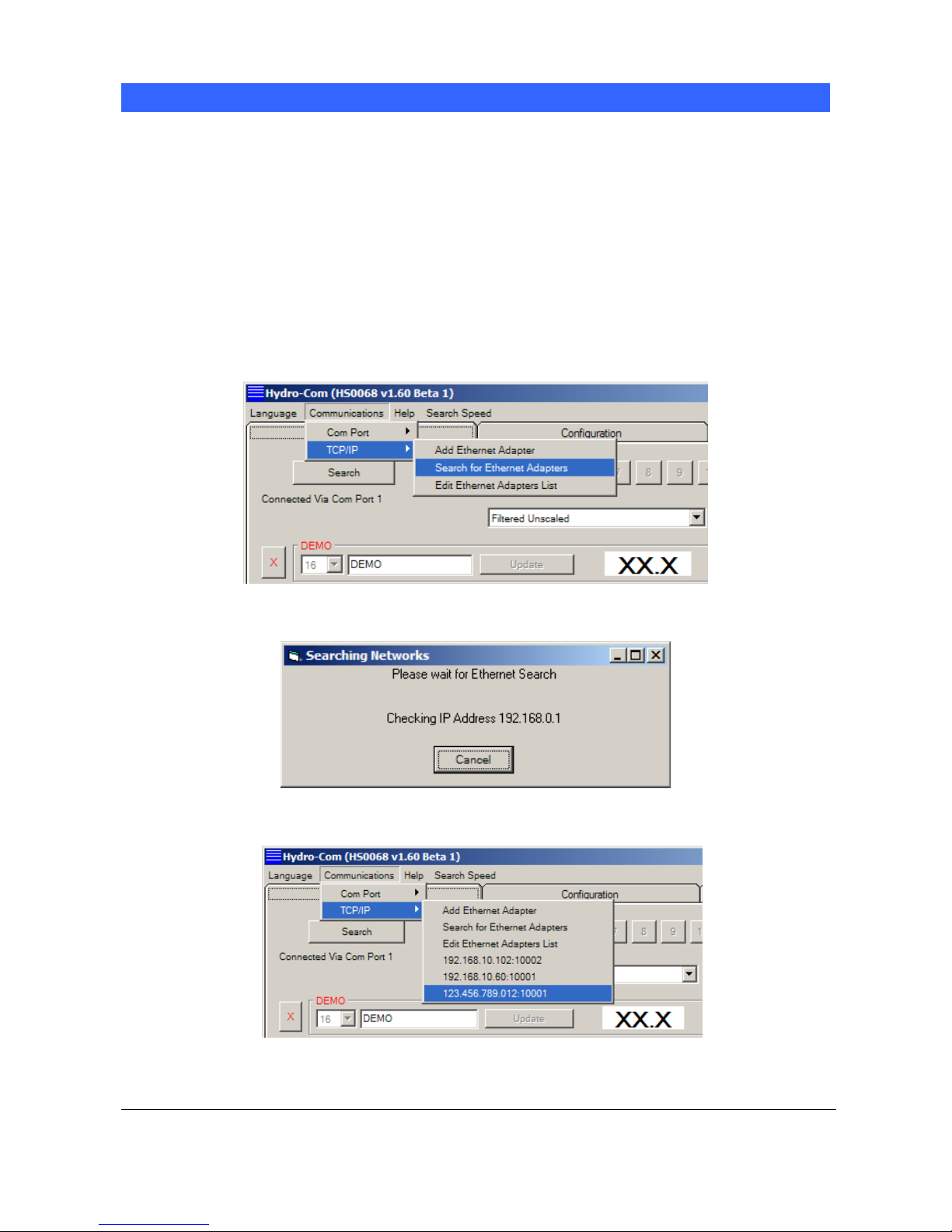
Communication with Hydronix sensors is carried out with the Hydro-Com Utility. To start go to the
Communications->TCP/IP menu in Hydro-Com and select “Search for Ethernet Adapters”.
The program will display a search window and query the network for any sensors attached.
The adapter will be added to the list, select it to connect.
Page 20

Chapter 4 Configuring the Ethernet Adapter
20
Ethernet Adapter User Guide
HD0333 Issue 2.0.0
Adding an Ethernet Adapter manually
In order to manually enter an Ethernet Adapter’s IP Address select Communications->TCP/IP->Add
Ethernet Adapter.
In the dialog that is shown, enter the IP Address and Port Number (usually 10001) of the Ethernet
Adapter
The adapter will be added to the list, select it to connect.
Page 21
Configuring the Ethernet Adapter Chapter 4
21
Ethernet Adapter User Guide
HD0333 Issue 2.0.0
Changing the Ethernet Adapter IP Address
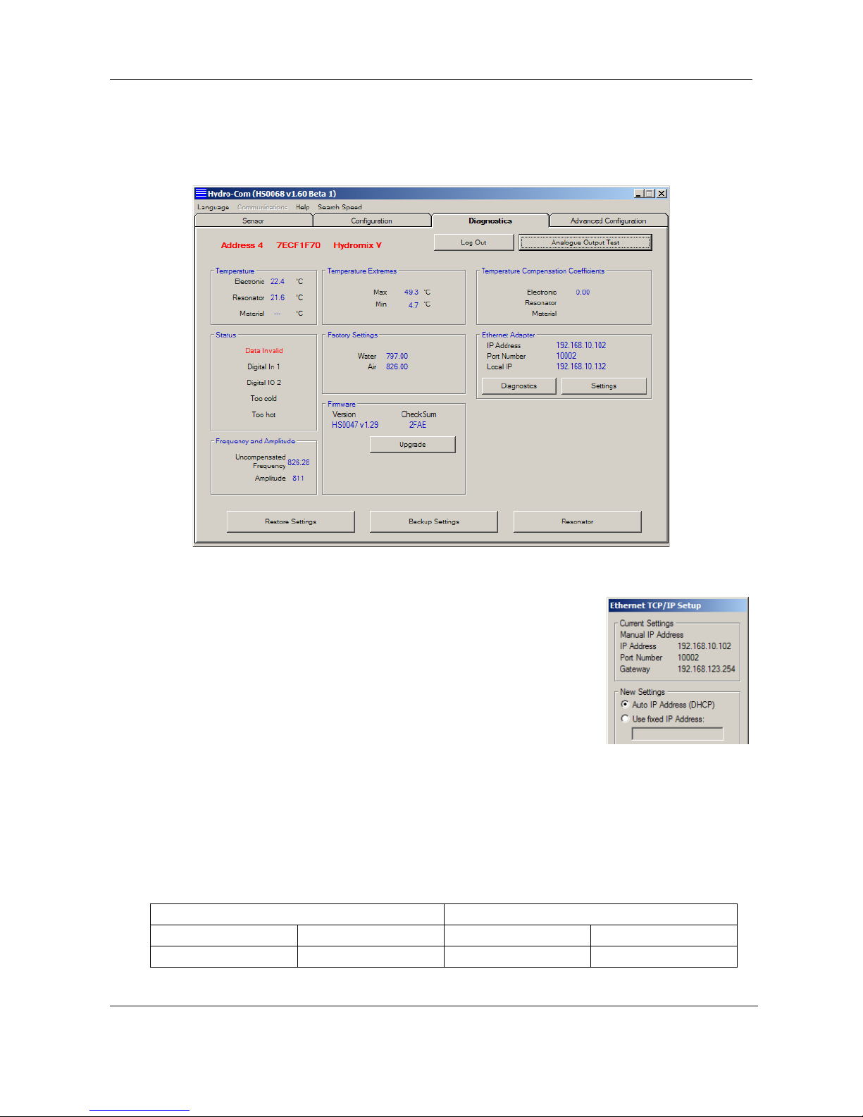
Once Hydro-com is connected to an Ethernet Adapter, go to the “Diagnostics” tab, login then click on the
button “Settings” in the Ethernet Adapter frame
To fix the IP Address, click on “Use fixed IP Address” and enter the IP
Address in the box provided. It is recommended to leave the Port Number
and Gateway set to the defaults. Click “Set” and then after the progress bar
has completed and the new information has been written, click “Exit” to close
the dialog and go back to the main screen.
When a fixed IP Address has been assigned, it is recommended to write the
address on the front of the Ethernet Adapter in the space provided.
Remote (Internet) Connection
Sensors connected to an Ethernet Adapter can also be accessed remotely over the Int ernet. In order to
do this, it is necessary to open up a port in the Firewall of the network on which the Ethernet Adapter is
installed. Contact the Network Administrator for details of doing this. When opening the Port, all incoming
traffic to that port should be directed to the IP Address of the Ethernet Adapter and port 10001. Make a
note of the network’s IP Address on the Internet and the number of the port opened up. The table below
shows the settings used in this example:
Company Network Settings Ethernet Adapter Settings
IP Address Opened Port IP Address Port Number
123.456.78.901 7011 192.168.10.61 10001
Page 22

Chapter 4 Configuring the Ethernet Adapter
22
Ethernet Adapter User Guide
HD0333 Issue 2.0.0
The port 7011 on the Firewall is opened up and all traffic to this port is forwarded to 192.168.10.61 port
10001.
If the Firewall does not allow a completely flexible configuration of port forwarding then either open up
port 10001 on the Firewall and leave the Ethernet Adapter port set as 10001, or alternatively alter the port
of the Ethernet Adapter to be the same as the port opened in the
Firewall. This is done by entering the new value in the Port Number
box when setting the fixed IP Address:
Certain port numbers are reserved for internal use by the Ethernet
Adapter and should not be used:
Port Number Function
1 – 1024
Commonly used Internet
Ports
9999
14000 –
14009
30704
30718
Ethernet Adapter Reserved
functionality
Hydro-Com prevents you from setting these port numbers.
Install Hydro-Com on the remote machine. As before, select Communications->TCP/IP->Add Ethernet
Adapter. In the Add Ethernet Adapter window, enter the IP Address of the Firewall and the Port opened.
Page 23

23
Ethernet Adapter User Guide
HD0333 Issue 2.0.0
Chapter 5 Technical Specifications
EA01 Ethernet Adapter
Dimensions: 70mm (w) x 86mm (h) x 57mm (d)
Environment: Operating Temperature 0-70°C
Modules should be used indoors in dry environments only. The enclosures are rated to IP31.
Interfaces: Ethernet IN: Standard 10/100baseT Ethernet RJ45 socket
RS485: Can connect to a maximum of 16 Hydronix Sensors
RS232: Standard RS232 interface
Weight: 160g
EPA01 Ethernet Power Adapter
Dimensions: 35mm (w) x 86mm (h) x 57mm (d)
Environment: Operating Temperature:0-70°C
Modules should be used indoors in dry environments only. The enclosures are rated to IP31.
Power Output: 24V, 630mA – see notes in Chapter 2 on number of sensors that can be powered.
Interfaces: Ethernet IN: Standard 802.11af 10/100baseT Power over Ethernet RJ45 socket
Ethernet OUT: Standard 10/100baseT Ethernet RJ45 socket
Weight: 123g
EPI01 Ethernet Power Injector
Dimensions: 65mm (w) x 140mm (h) x 36mm (d)
Environment: Operating Temperature: 0-40°C
Modules should be used indoors in dry environments only.
Interfaces: Mains In: IEC320 inlet 3 pin
Ethernet IN: Standard 10/100baseT Ethernet RJ45 socket
Ethernet OUT: Standard 802.11af 10/100baseT Power over Ethernet RJ45 socket
Weight: 246g
NOTE: Allow space for cables to be fitted on all units
Page 24
Chapter 5 Technical Specifications
24
Ethernet Adapter User Guide
HD0333 Issue 2.0.0
Terminal Identification
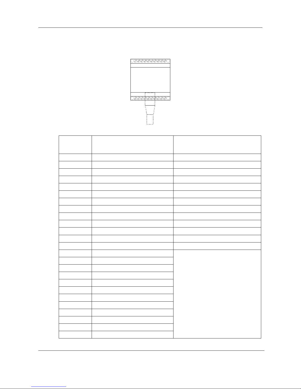
The Ethernet Adapter terminals are wired as follows:
EA01
Ethernet
Adapter
1 12
13 24
IN
Figure 6: EA01 Terminal Identification
Ethernet
Adapter
Terminal
Signal
Description
Notes
IN CAT5e Network cable
1 24V + input
2 0V input
3 24V + to sensor
4 0V to sensor
5 RS485 B
6 RS485 A
7 No connection
8 RS232 RTS
9 RS232 Tx
10 RS232 Rx
11 RS232 CTS
12 RS232 GND
13 24V + to sensor
14 0V to sensor
15 RS485 B
16 RS485 A
17 24V + to sensor
18 0V to sensor
19 RS485 B
20 RS485 A
21 24V + to sensor
22 0V to sensor
23 RS485 B
24 RS485 A
It is not recommended to wire RS485
using a star topology
Please refer to chapter 3 on RS485
wiring recommendations
Page 25
Technical Specifications Chapter 5
25
Ethernet Adapter User Guide
HD0333 Issue 2.0.0
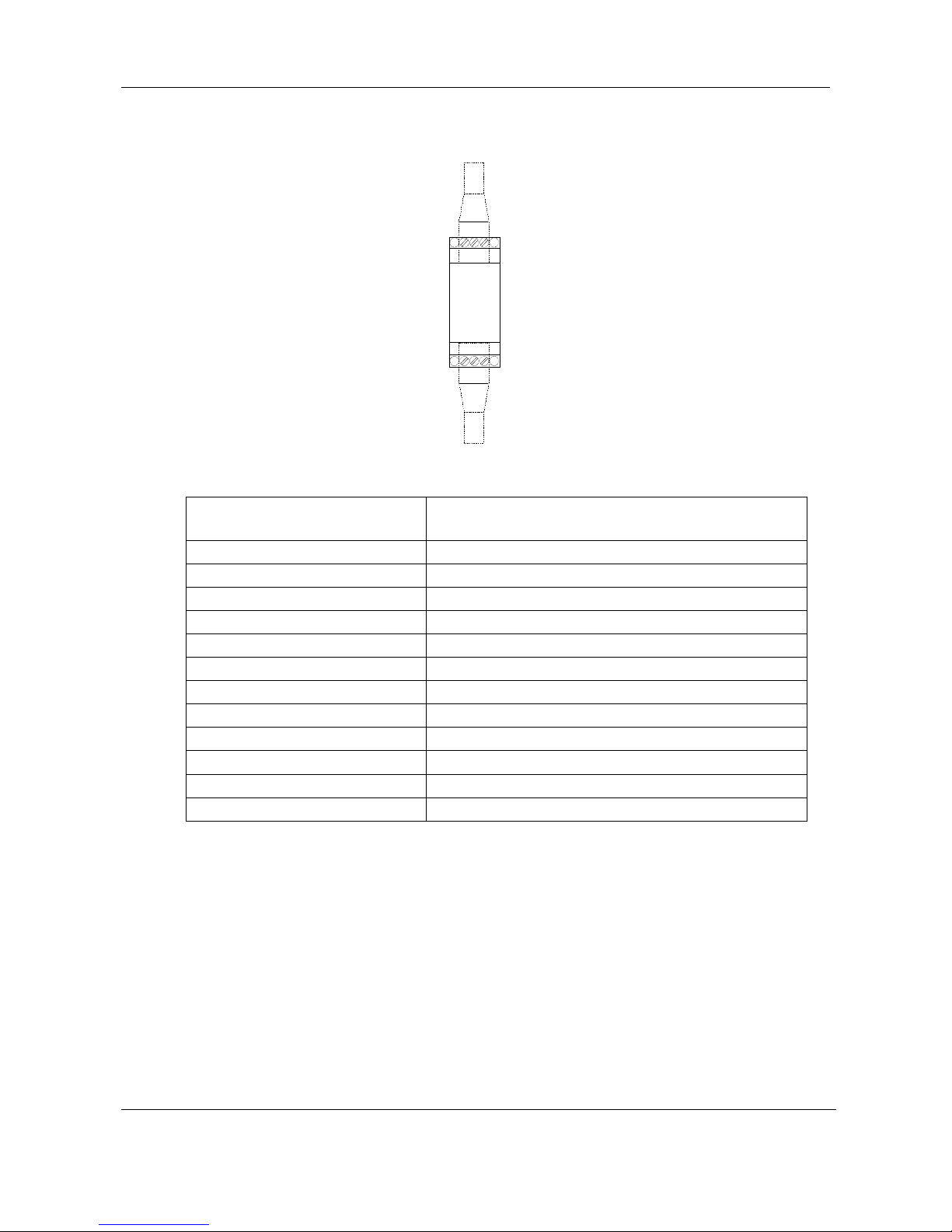
The Ethernet Power Adapter EPA01 terminals are wired as follows. Particular care must be taken to
identify the top and bottom of the unit, as both sides look similar.
EPA01
Ethernet
Power
Adapter
6 10
1 5
IN
OUT
Figure 7: EPA01 Terminal Identification
Ethernet Power Adapter
Terminal
Signal
Description
IN CAT5e Network cable from EPI01
OUT CAT5e Network cable to EA01
1 0V output
2 0V output
3 No connection
4 24V + output
5 24V + output
6 0V output
7 0V output
8 No connection
9 24V + output
10 24V + output
Page 26

Chapter 5 Technical Specifications
26
Ethernet Adapter User Guide
HD0333 Issue 2.0.0
Page 27

27
Ethernet Adapter User Guide
HD0333 Issue 2.0.0
Chapter 6 Fault Finding
Ethernet Adapter EA01
Symptom: 24V light not on
Possible Explanation Check Required Result
Action required on
failure
24V not connected
DC power on terminals 1
and 2
+24v DC
Locate fault in power
supply
Symptom: Not found on network using the Hydro-Com Search function
Possible Explanation Check Requir ed Result
Action required on
failure
Not connected to
network
Ethernet link Ethernet link light lit
Locate fault in network
cabling
No DHCP address DHCP server IP address assigned
Unplug and replug the
network cable
Ethernet Power Adapter EPA01
Symptom: 24V light not on
Possible Explanation Check Required Result
Action required on
failure
Ethernet Power Injector
not connected
Ethernet Power Injector
EPI01 as above
24V light on
Ethernet cables plugged
in wrong way round
Try swapping the cables
– the Power Injector
should go to IN and the
OUT should go to the
Ethernet Adapter
24V light on
Symptom: Computer does not communicate with the Ethernet Adapter
Possible Explanation Check Required Result
Action required on
failure
Not properly registered
on network
Search for the Ethernet
adapter using the HydroCom ‘Search’ function.
If that fails then try
pinging the IP address
of the Ethernet Adapter
Ethernet Adapter found
Ping response
Investigate network – try
power cycling EA01
Check IP Address
Invalid IP address
If the subnet mask is
255.255.255.0 then if
the adapter’s IP address
x.y.z.a then the PC’s
must be x.y.z.b (b <> a)
try changing the PC’s to
match and try again
Connection from
HydroCom to Ethernet
Adapter – then the IP
Address can be
changed
Contact local network
administrator or
Hydronix Technical
Support
Page 28

Chapter 6 Fault Finding
28
Ethernet Adapter User Guide
HD0333 Issue 2.0.0
Symptom: Computer does not communicate with the sensor
Possible Explanation Check Required Result
Action required on
failure
Not wired correctly to
sensor
Wiring connections of
EA01
Transmit and receive
lights blink
Check sensor
connections, try a
different sensor
Ethernet Power Injector EPI01
Symptom: ON light not illuminated
Possible Explanation Check Required Result
Action required on
failure
Ethernet Power Injector
not plugged in
Power supply to Ethernet
Power Injector
ON light illuminated Try a different EPI01
Symptom: CONNECT light not illuminated
Possible Explanation Check Required Result
Action required on
failure
Ethernet cable to
Ethernet Power Adapter
faulty or not connected
Cable between EPI01
and EPA01
CONNECT light
illuminated
Replace cable or try a
different EPA01
Page 29

Index
29
Ethernet Adapter User Guide
HD0333 Issue 2.0.0
Index
Connections 13
Internet / Remote 25
Custom Application 21
Defaults 23
DHCP 23
Dimensions 27
Ethernet Adapter
Connections 30
Connections for Sensor 13
Defaults 23
Fault Finding 33
Hydro-Control V Connections 21
Indicator Lights 15
Installation 9
IP Address 23
Location 9, 17
Terminals 30
Ethernet Adapter Kit
Contents 8
Ethernet Power Adapter
Connections 14, 31
Fault Finding 33
Indicator Lights 15
Location 10, 20
Terminals 31
Ventilation 10
Ethernet Power Adapter Kit
Contents 8
Ethernet Power Injector
Fault Finding 34
Indicator Lights 15
Location 13, 21
Number of Sensors 13
Hydro-Control V
Connections 17, 21
Ethernet Adapter Location 17
Ethernet Power Adapter 20
Installation 17
Hydro-Link 21
Indicator Lights 15
Installation 9
Ethernet Adapter 9
Ethernet Power Adapter 10
Hydro-Control V 17
Interfaces
Ethernet Adapter 27
Ethernet Power Adapter 27
Ethernet Power Injector 27
Internet Connection 25
IP Address 23
Kit Options 8
Operating Temperature 27
Port Numbers 26
Power Injector Module
Sensor Connections 21
Power Output 27
Power over Ethernet
Installation 10, 20
Programming 21
Remote Access 25
Remote Connection 25
RS-485
Wiring 14
TCP/IP Menu 23
Temperature 27
Number of Sensors 10
Terminal Identification 30
Ventilation 10
Weight 27
Wiring 13
RS-485 14
 Loading...