

Hydronic D 4 W SC – 12 V, D 5 W SC – 12 V Technical Description, Installation, Operating And Maintenance Instructions
Page 1
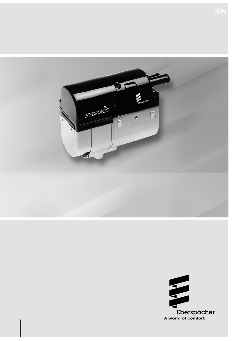
HYDRONIC
Technical Description, Installation,
Operating and Maintenance Instructions.
Heater Order No.
Hydronic D 4 W SC – 12 V 25 2096 05 00 00
Hydronic D 4 W SC – 12 V 25 2097 05 00 00
as a complete package
Heater Order No.
Hydronic D 5 W SC – 12 V 25 2098 05 00 00
Hydronic D 5 W SC – 12 V 25 2099 05 00 00
as a complete package
Hydronic D 5 W SC – 24 V 25 2147 05 00 00
Engine-independent water heater
for diesel and petrol.
25 2096 90 95 33
11.2014
Page 2

Introduction1
Contents
Chapter Title Content Page
1
2
3
4
5
6
7
8
Introduction
Product information
Installation
Operation and function
Electrics
Troubleshooting
Maintenance
Service
Environment
Lists
• Contents .................................................................................................... 2
• Concept of this manual .............................................................................. 3
• Special text structure, presentation and picture symbols ......................... 4
• Important information before starting work ............................................... 4
• Statutory regulations ............................................................................. 5, 6
• Safety instructions for installation and operation ...................................... 7
• Accident prevention .................................................................................. 7
• Scope of supply ..................................................................................... 8, 9
• Technical data ..........................................................................................10
• Main dimensions .......................................................................................11
• Installation and mounting position ............................................................ 12
• Permissible installation positions ..............................................................13
• Installation and fixing................................................................................ 13
• Nameplate ................................................................................................ 14
• Connection to the cooling water circuit ......................................... 15 – 18
• Exhaust system .........................................................................................19
• Combustion air system .............................................................................. 20
• Fuel supply ...................................................................................... 21 – 27
• 12 volt heater fuel supply .................................................................. 22, 23
• 24 volt heater fuel supply ................................................................ 24 – 26
• Operating instructions / important instructions for operation .................. 28
• Initial commissioning ................................................................................. 28
• Functional description .............................................................................. 28
• Control and safety devices ....................................................................... 29
• Wiring of the heater.................................................................................. 30
• Parts list for circuit diagram, 12 volt heater ............................................. 31
• Circuit diagram for 12 volt heater ............................................................ 32
• Parts list for circuit diagram, 24 volt / 24 volt ADR heater ...................... 33
• Circuit diagrams for 24 volt / 24 volt ADR heater ............................. 24, 35
• Parts list for circuit diagrams, EasyStart R+ / R / T and
EasyStart T – ADR control units .............................................................. 36
• Circuit diagrams for EasyStart R+ / R / T and EasyStart T –
ADR control units ............................................................................ 37 – 40
• If any faults occur, please check the following items ...............................41
• Troubleshooting ........................................................................................ 41
• Maintenance instructions ......................................................................... 41
• Service ..................................................................................................... 41
• Certifications ............................................................................................ 42
• Disposal .................................................................................................... 42
• EC Declaration of Conformity .................................................................... 42
• List of abbreviations ..................................................................................43
2
Page 3

Introduction1
Concept of this manual
This manual aims to support the service company
installing the heater and to provide the user with all
important information about the heater.
The manual has been divided into 8 chapters to make
it easier to find the corresponding information quickly.
Introduction
1
This section contains important introductory
information about installing the heater and
about the structure of the manual.
Product information
2
Here you will find information about the scope of
supply, the technical data and the dimensions of
the heater.
Installation
3
Here you will find important information and
instructions referring to installation of the
heater.
Operation and function
4
Here you will find information about the operation and function of the heater.
Electrics
5
Here you will find information about the electronic system and electronic components of the
heater.
Troubleshooting / maintenance / service
6
Here you will find information about possible
faults, troubleshooting, servicing / maintenance
and the service hotline.
Environment
7
Here you will find information about certification
and disposal of the heater together with the EC
Declaration of Conformity.
Lists
8
Here you will find the list of abbreviations.
3
Page 4
Introduction
1
Special text structure, presentation and
picture symbols
This manual uses special text structures and picture
symbols to emphasize different contents.
Please refer to the following examples for their meanings and appropriate action.
Special text formats and presentations
A dot (•) indicates a list which is started by a heading.
If an indented dash (–) follows a dot, this list is subordinate to the dot.
Picture symbols
Regulation!
This picture symbol with the remark “Regulation!”
refers to a statutory regulation.
Failure to comply with this regulation results in expiry
of the type-approval for the heater and preclusion of
any guarantee and liability claims on J. Eberspächer
GmbH & Co. KG.
Danger!
This picture symbol with the remark “Danger!” refers
to the risk of a fatal danger to life and limb.
Under certain circumstances, failure to comply with
these instructions can result in severe or life-threatening injuries.
Caution!
This picture symbol with the remark “Caution” refers
to a dangerous situation for a person and / or the
product.
Failure to comply with these instructions can result in
injuries to people and / or damage to machinery.
Please note!
These remarks contain recommendations for use and
useful tips for installation of the heater.
Important information before starting
work
Range of application of the heater
The water heater operating independently of an engine
is intended for installation in the following vehicles:
• All kinds of vehicles
• Construction machinery
• Agricultural machinery
• Boats, ships and yachts
Please note!
Only the Hydronic D5 W SC – 24 volt heater is approved for installation in vehicles used for the transport
of dangerous goods according to ADR.
For installation of the heater in vehicles used for
the transport of dangerous goods, the ADR regulations
must also be observed.
Detailed information on the ADR regulations is given in
the information sheet, Print No. 25 2161 95 15 80.
Intended purpose of the heater
(via the vehicle’s own heat exchanger)
• Pre-heating, de-misting windows
• Heating and keeping the following warm:
– Driver and working cabs
– Freight compartments
– Ships cabins
– Passenger and crew compartments
– Vehicle engines and units
On account of its functional purpose, the heater is not
approved for the following applications:
• Long-term continuous operation, e.g. for heating of:
– Residential rooms
– Garages
– Work huts, weekend homes and hunting huts
– Houseboats, etc.
Caution!
Safety instructions for the range of application and
proper, intended use!
• The heater may only be used and operated for the
range of applications stated by the manufacturer in
compliance with the “Operation instructions” included
with every heater.
4
Page 5
Introduction
1
Statutory regulations
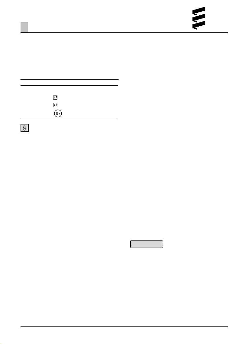
The Federal Motor Transport Authority has issued an
"EC type approval", "EMC type-approval" and the approval for a component according to ECE R122 and
ECE-R10 for the heater for installation in motor vehicles
with the following official type-approval marks, noted on
the heater name plate.
Heater type: Hydronic
Test mark:
EC 00 0023
EMC 031075
122 R - 000023
ECE
Regulations
Extract from Directive 2001 / 56 / EC Annex VII and
ECE Regulation No. 122 of the European Parliament
and of the Council
General regulations
• Operating state display
– A clearly visible operating display in the user's
field of vision must indicate when the heater is
switched on and off.
Regulations concerning installation in the vehicle
• Scope
– Subject to differing stipulations in the following
section, combustion heaters must be installed
according to the provisions of Directive 2001 / 56
/ EC Annex VII.
– It is assumed that Class O vehicles with heaters
for liquid fuel conform to the provisions of Directive
2001 / 56 / EC.
• Arrangement of the heater
– Parts of the structure and other components near
the heater must be protected from excessive heat
exposure and possible fuel or oil contamination.
– The heater must not pose a fire hazard even when
it overheats. This requirement is deemed to be
fulfilled if adequate clearance is ensured for all
parts during installation, sufficient ventilation is
provided and fireproof materials or heat shields are
used.
– The heater must not be mounted in the passenger
compartment of vehicles in class M2 and M3.
However, a heater in a hermetically sealed
enclosure which also complies with the aforementioned conditions may be used.
10 R - 041075
– The factory nameplate or duplicate must be affixed
so that it can still be easily read when the heater
is installed in the vehicle.
– All appropriate precautions must be taken when
arranging the heater to minimise the risk of
injuries to persons or damage to other property.
• Fuel supply
– The fuel intake connection must not be located in
the passenger compartment and must be sealed
with a properly closing lid to prevent any fuel
leaks.
– In heaters for liquid fuel where the heater fuel is
separate from the vehicle fuel, the type of fuel and
intake connection must be clearly identified.
– A warning sign is to be fixed to the intake
connection indicating that the heater must be
switched off before refuelling.
• Exhaust system
– The exhaust outlet must be arranged so as to
prevent any penetration of exhaust fumes into the
vehicle interior through the ventilation system,
warm air intakes or open windows.
• Combustion air intake
– The air for the heater's combustion chamber must
not be sucked in from the vehicle's passenger
compartment.
– The air intake must be arranged or protected in
such a way that it cannot be blocked by other
objects.
• Automatic control of the heating system
– If the engine fails, the heating system must be
automatically switched off and the fuel supply
stopped within 5 seconds. The heater may remain
in operation if a manual device has already been
activated.
Please note!
The heater is not approved for installation in the interior of Class M1 vehicles (vehicles for passenger transport
/ cars) and N vehicles (vehicles for the transport of
goods).
5
Page 6

Introduction
1
Statutory regulations
Please note!
• Compliance with the statutory regulations, the
additional regulations and the safety instructions is
prerequisite for guarantee and liability claims.
Failure to comply with the statutory regulations and
safety instructions and incorrect repairs, even if
original spare parts are used, make the guarantee
null and void and preclude any liability for J.
Eberspächer GmbH & Co. KG.
• Subsequent installation of this heater must comply
with these installation instructions.
• The statutory regulations are binding and must also
be observed in countries which do not have any
special regulations.
• When installing the heater in vehicles not subject to
the German Road Traffic Licensing Regulations
(StVZO), for example ships, the respective specially
valid regulations and installation instructions must be
observed.
• Installation of the heater in special vehicles must
comply with the regulations applying to such vehicles.
• Other installation requirements are given in the
relevant sections of these installation instructions.
6
Page 7
Introduction
1
Safety instructions for installation and
operation
Danger!
Risk of injury, fire and poisoning!
• Disconnect the vehicle battery before starting any
kind of work.
• Before working on the heater, switch the heater off
and let all hot parts cool down.
• The heater may not be operated in enclosed spaces,
e.g. in the garage or in a multi-storey car park.
Caution!
Safety instructions for installation and operation!
• The heater must only be installed by a JE partner
authorised by the manufacturer according to the
instructions in this manual and possibly according to
special installation recommendations; the same
applies to any repairs to be carried out in the case of
repairs or guarantee claims.
• Repairs by non-authorised third-parties and / or with
non-original spare parts are dangerous and are
therefore not allowed. They result in expiry of the
type-approval of the heater; consequently, when
installed in motor vehicles they can cause expiry of
the vehicle’s operating licence.
• The following measures are not allowed:
– Changes to components relevant to the heater.
– Use of third-party components not approved by J.
Eberspächer GmbH & Co. KG.
– Installation or operation not conforming to the
statutory regulations, safety instructions or
specifications relevant for safe operation as stated
in the installation instructions and operating
instructions. This applies in particular to the
electrical wiring, fuel supply, combustion air
system and exhaust system.
• Original accessories and original spare parts only may
be used for installation or repairs.
• Only the control units approved by Eberspächer may
be used to operate the heater. Use of other control
units can cause malfunctions.
• Before the heater is installed again in another
vehicle, rinse the heater parts carrying water with
clear water.
• When carrying out electric welding on the vehicle,
the positive cable at the battery should be disconnected and placed at ground to protect the control
box.
• The heater must not be operated where there is a
risk of an accumulation of flammable vapours or dust,
e.g. close to
– Fuel depot
– Coal depot
– Wood depot
– Grain depot, etc.
• The heater must be switched off when refuelling.
• If the heater is installed in a safety casing or similar,
its installation box must not be used as storage space
and must be kept clear. In particular fuel canisters, oil
cans, spray cans, gas cartridges, fire extinguishers,
cleaning rags, items of clothing, paper etc. must not
be stored or transported on or next to the heater.
• Defective fuses may be replaced by fuses with the
prescribed rating only.
• If fuel leaks from the heater fuel system, arrange for
the damage to be repaired immediately by a JE
service partner.
• When topping up the coolant, only use the coolant
permitted by the vehicle manufacturer, see the
vehicle operating manual. Any blending with
unapproved coolant can cause damage to the engine
and heater.
• The after-running of the heater must not be
prematurely interrupted e.g. by pressing the battery
isolating switch, except for an emergency stop.
Accident prevention
General accident prevention regulations and the corresponding workshop and operating safety instructions
are to be observed.
7
Page 8

Product information
2
Scope of supply
Quantity / Designation Order No.
1 Hydronic D 4 W SC – 12 V
To be ordered separately:
1 Universal installation kit 25 1917 80 00 00
1 Control unit** –
or
1 Hydronic D 4 W SC – 12 V
as a complete package*
To be ordered separately:
1 Control unit** –
or
1 Hydronic D 5 W SC – 12 V
To be ordered separately:
1 Universal installation kit 25 1917 80 00 00
1 Control unit** –
or
1 Hydronic D 5 W SC – 12 V
as a complete package*
To be ordered separately:
1 Control unit** –
25 2096 05 00 00
25 2097 05 00 00
25 2098 05 00 00
25 2099 05 00 00
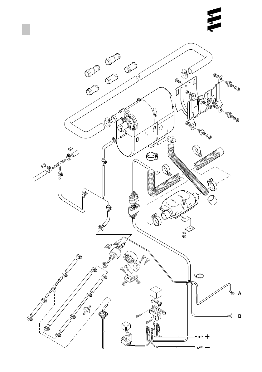
Parts list for the picture “Scope of supply” on page 9
Scope of supply for petrol heater
Figure No. Designation
1 Heater
2* Metering pump
* with Hydronic D 5 W SC-24 V only
Scope of supply for universal installation kit
Figure No. Designation
3 Exhaust silencer
4 Cable harness, heater
5 Lead harness, positive
6 Bracket, heater
7 Water hose
8 Flexible exhaust pipe
9 Cable tie
10* Bracket, metering pump
11* Pipe, 6 x 2
12 Combustion air hose
13* Hose, 5 x 3
14* Pipe, 4 x 1
15* Tank connection
16* Fuel filter
17 Hose, 3.5 x 3
* Included in installation kit 25 2009 80 00 00 only.
1 Hydronic D 5 W SC – 24 V
25 2147 05 00 00
To be ordered separately:
1 Universal installation kit 25 2009 80 00 00
1 Control unit** –
* The complete package contains:
1 Heater
1 Universal installation kit
**Control units, see price list / accessories catalogue.
8
Cable harnesses
(A) Lead harness, “control units”
(B) Lead harness, “fan activation”
Please note!
• Parts without a figure No. are small parts and are
packed in a bag.
• Please consult the additional parts catalogue if any
other parts are required for the installation.
Page 9
Product information
2
Scope of supply
7
1
6
12
17
13*
11*
16*
2*
14*
15*
10*
8
3
4
9
5
9
Page 10
Product information
2
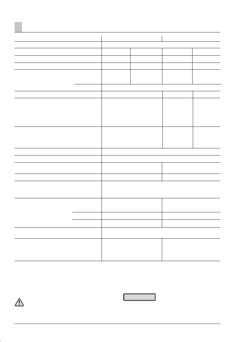
Technical data / diesel heaters
Heating medium
Control of the heat flow
Heat flow (watt)
Fuel consumption (l/h)
Average elec. power consumption (watt)
during operation
while starting
Rated voltage
Operating range
• Lower voltage limit:
An undervoltage protection installed in the
control box switches off the heater if the
voltage limit is reached.
• Upper voltage limit:
An overvoltage protection installed in the
control box switches off the heater if the
voltage limit is reached.
Allowable operating pressure
Water volume in the heater
Water flow rate of the water pump against
0.1 bar
Minimum water flow rate of the heater
Fuel – see also “Diesel Heater Fuel Quality”
page 30
Allowable ambient temperature
Heater
Control box
Metering pump
Interference suppression class
Weight – without coolant and attachments
Hydronic D 4 W SC Hydronic D 5 W SC
Water, coolant
High Low High Low
4300 2400 5000 2400
0.53 0.27 0.62 0.27
48 23 50 23
120
12 volt 12 volt 24 volt
10.2 volt 10.2 volt 20.4 volt
16 volt 16 volt 32 volt
up to 2.5 bar overpressure
0.18 l
500 l/h ±70 l/h 900 l/h ±100 l/h
250 l/h 300 l/h
Diesel – commercially available (EN 590)
FAME for diesel engines according to EN 14 214
– for Hydronic D 5 W SC – 24 volt only
in operation without operation
–40 °C to +80 °C –40 °C to +105 °C
–40 °C to +80 °C –40 °C to +105 °C
–40 °C to +20 °C –40 °C to +105 °C
5
to DIN 57879 / Part 1 VDE 0879
approx. 2.7 kg approx. 2.9 kg
with metering pump
approx. 2.7 kg
without metering pump
Caution!
Safety instructions for technical data!
Failure to comply with the technical data can result in
malfunctions.
10
Please note!
If no limit values are given, the technical data listed is
with the usual heater tolerances of ± 10 % at nominal
voltage, 20 °C ambient temperature and Esslingen
reference altitude.
Page 11
Product information
2
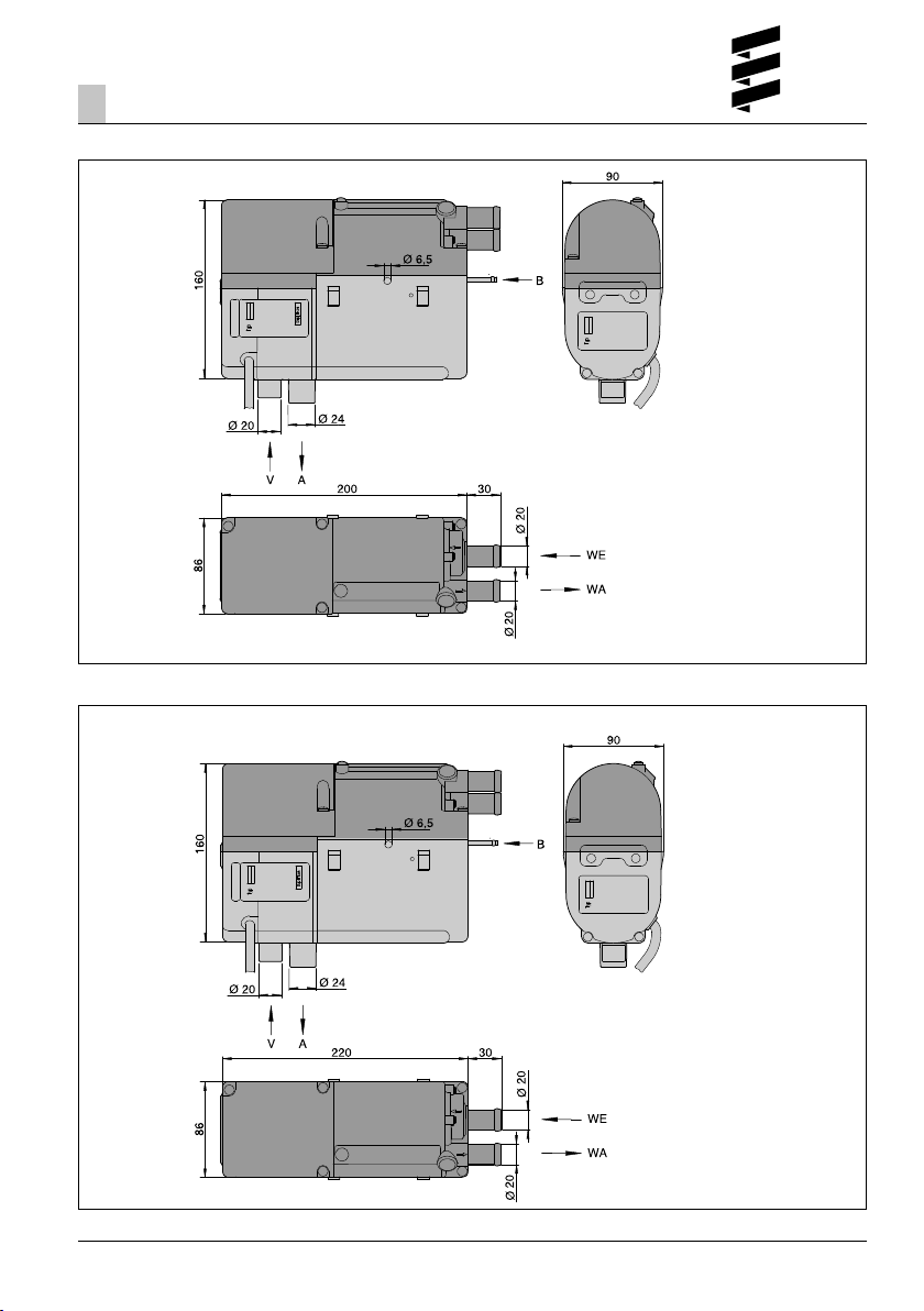
Main dimensions D 4 W SC
Main dimensions D 5 W SC
WE Water inlet
WA Water outlet
A Exhaust
BFuel
V Combustion air
WE Water inlet
WA Water outlet
A Exhaust
BFuel
V Combustion air
11
Page 12
Installation
3
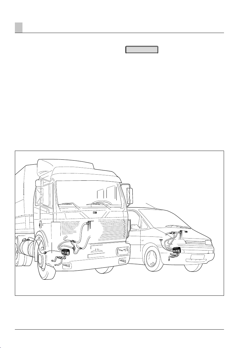
Installation and mounting position
The heater is installed in the engine compartment. The
heater must be installed below the min. cooling water
level (header tank, radiator, vehicle’s heat exchanger)
so that the heat exchanger of the heater and water
pump can vent independently.
Installation example
10
Please note!
• Observe the regulations and safety instructions for
this chapter, given on page 4 – 7.
• The positions suggested in the installation instructions
are examples. Other installation locations are possible
if they comply with the installation requirements
stated in these installation instructions.
• Further installation information (e.g. for boats and
ships) is available from the manufacturer on request.
• Note and observe the permissible installation positions
as well as the operating and storage temperatures.
7
8
9
2
4
5
6
1
3
1 Heater
2 Exhaust pipe with exhaust silencer
3 Combustion air hose
4 Non-return valve
5 T-piece (water circuit)
12
7
4
10
8
1
3
2
6 Thermostat
7 Vehicle heat exchanger with blower
8 Tank connection / T-piece (fuel)
9 Metering pump (24 volt version only)
10 Module timer
Page 13
Installation3
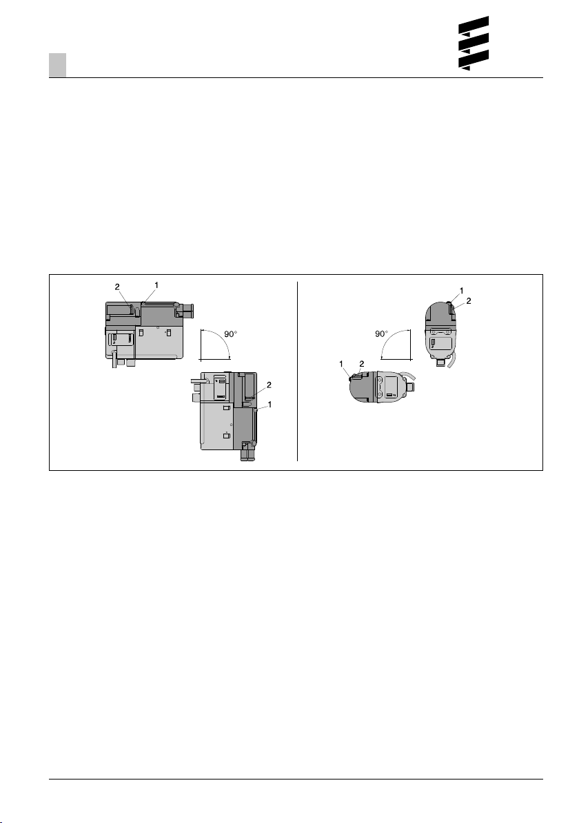
Permissible installation positions
The heater should preferably be installed in the normal
position, horizontally with the exhaust connection
facing downwards.
Depending on the installation conditions, the heater
can be installed within the permissible swivel ranges,
see sketch.
Normal position with permissible swivel ranges
• Swivel range swung by up to max. 90° downwards
from the normal position – the water pipe sockets are
pointing downwards.
1 Vent screw – must always be at the top
2 Fuel connection
In heating mode, the normal and maximum installation
positions shown can differ by up to +15° in all directions for a short time. These differences, caused by
tilted positions of the vehicle, do not have any negative
effects on the heater’s function.
• Swivel range swung from the normal position by up to
max. 90° about the longitudinal axis – the water pipe
sockets are horizontal.
Installation and fixing
Insert the heater in the heater bracket and fasten with
fixing screws (tightening torque 6
bracket with the installed heater in a suitable position
in the engine compartment, if possible with rubber
buffer.
+0.5
Nm). Fix the heater
13
Page 14
Installation
3
Nameplate
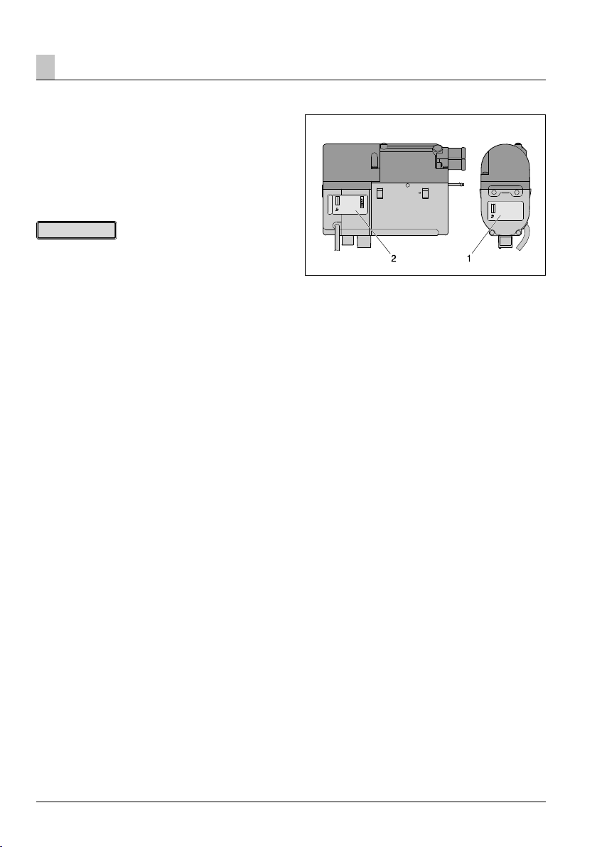
The nameplate and the 2nd nameplate (duplicate) is
fixed to the side, on the lower jacket shell. The 2nd
nameplate (duplicate) is attached to the lower jacket
shell; it is removable and, if necessary, can be stuck
onto a clearly visible place on the heater or in the area
of the heater.
Please note!
The regulations and safety instructions to be observed
for this chapter are stated on page 5.
1 Original nameplate
2 2nd nameplate (duplicate)
14
Page 15

Installation
3
Connection to the cooling water circuit
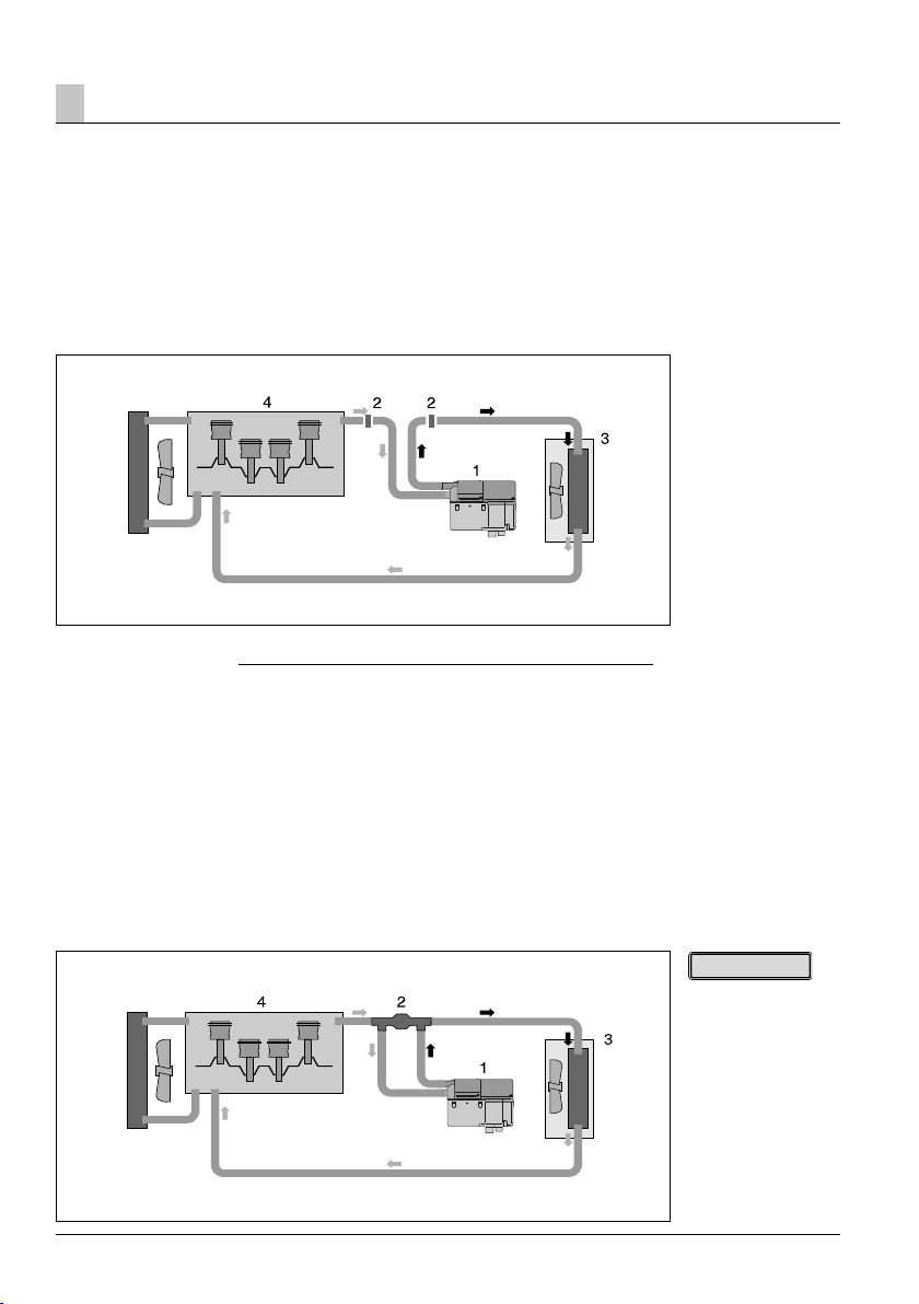
The heater is integrated in the cooling water circuit, in
the water flow hose from the vehicle engine to the heat
exchanger; for which there are four installation options.
The installation options are described on pages 19 –
21.
Danger!
Risk of injuries and burns!
It is possible for the coolant and components of the
coolant circuit to get very hot.
• Parts conveying water must be routed and fastened
in such a way that they pose no temperature risk to
man, animals or material sensitive to temperature
from radiation / direct contact.
• Before working on the coolant circuit, switch the
heater off and wait until all components have cooled
down completely, if necessary wear safety gloves.
Please note!
• When installing the heater, please note the direction
of flow of the cooling water circuit.
• Fill the heater and water hoses with coolant before
connecting them to the cooling water circuit; to do
this, open the vent screw on the heater.
• Route the water hoses without any kinks, and in a
rising position if possible.
• When routing the water pipes, maintain sufficient
clearance from hot vehicle parts.
• Protect all water hoses / water pipes from chafing
and from extreme temperatures.
• Secure all hose connections with hose clips
(tightening torque = 1.5 Nm).
• Re-tighten the hose clips after the vehicle has been
running for 2 hours or has travelled 100 km.
• The minimum water flow rate is only guaranteed if the
temperature difference of the heating medium does
not exceed 10 K between water inlet and water
outlet during heating.
• Only overpressure valves with an opening pressure of
min. 0.4 – max. 2 bar may be used in the coolant
circuit.
• The coolant liquid must contain at least 10 %
antifreeze all year round as corrosion protection.
• The cooling liquid must contain sufficient antifreeze
for low temperatures.
• Before commissioning the heater or after changing
the cooling liquid, the whole coolant circuit including
heater must be vented free of bubbles according to
the instructions issued by the vehicle manufacturer.
• Top up using only coolant approved by the vehicle
manufacturer.
15
Page 16
Installation
3
Connection to the cooling water circuit
Integrate heater in the water flow hose from the
vehicle engine to the heat exchanger, “inline
connection”
Cut the water flow hose from the vehicle engine to the
vehicle’s heat exchanger. Use connectors and water
hoses to connect the heater to the water flow hose.
Integrate the heater and non-return valve in the
cooling water circuit
Cut the water flow hose from the vehicle engine to the
vehicle’s heat exchanger and insert the non-return
valve. Use water hoses to connect the heater to the
non-return valve.
Heating characteristics
If the heater is switched on, the heat is fed to the
vehicle’s own heat exchanger and to the vehicle’s
engine. After the cooling water has reached a temperature of approx. 30 °C – depends on the selected
blower setting – the vehicle blower switches on and
the heat is then also fed to the passenger
compartment.
1 Heater
2 Connector
3 Heat exchanger
4 Vehicle engine
Heating characteristics
If the heater is switched on, the heat is initially fed via
the heater’s own heat exchanger to the vehicle’s engine only. After the cooling water has reached a temperature of approx. 30 °C – depends on the selected
blower setting – the vehicle blower switches on and
the heat is then also fed to the passenger
compartment.
Advantage of the “inline connection” water circuit
No loss of vehicle heating effectiveness if heater is
switched off.
Please note!
Non-return valve must
be ordered separately,
please refer to the
additional parts catalogue for the Order No.
1 Heater
2 Non-return valve
3 Heat exchanger
4 Vehicle engine
16
Page 17
Installation
3
Connection to the cooling water circuit
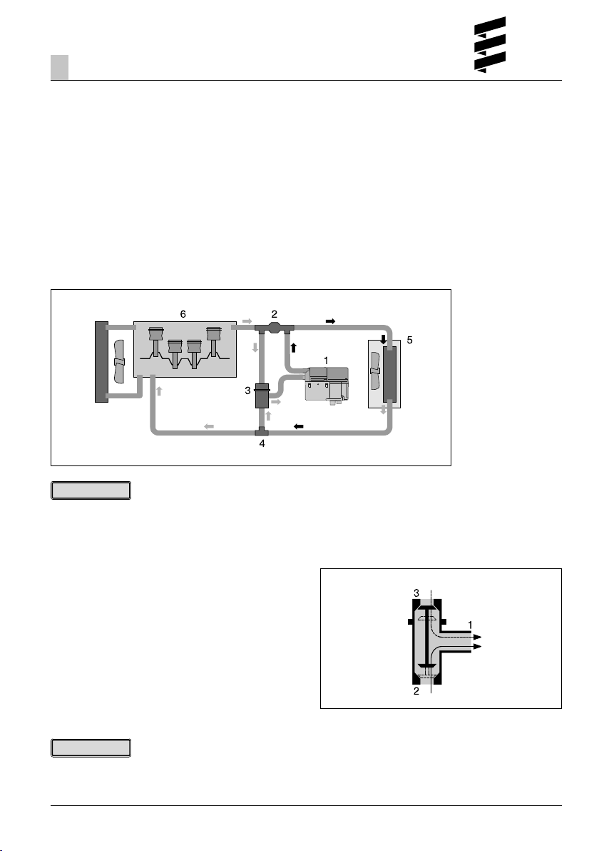
Integrate the heater, non-return valve, thermostat
and T-piece in the cooling water circuit (for Hydronic
B 5 W SC / D 5 W SC only)
Cut the water flow hose from the vehicle engine to the
vehicle’s heat exchanger and insert the non-return
valve. Cut the water return hose from the heat exchanger to the vehicle engine and insert the T-piece.
Use water hoses to connect the heater and the thermostat to the non-return valve and the T-piece – as
shown in the sketch.
Please note!
The thermostat, non-return valve and T-piece must be
ordered separately, please refer to the additional parts
catalogue for the Order No.
Heating characteristics
Small cooling water circuit
Initially, up to a cooling water temperature of approx.
70 °C, the heater’s heat is fed to the heat exchanger
only – fast heating of the inside of the vehicle.
Large cooling water circuit
If the cooling water temperature continues to rise, the
thermostat slowly switches over to the large circuit (full
switchover is reached at approx. 75 °C) – heating of
the inside of the vehicle and additional engine
pre-heating.
1 Heater
2 Non-return valve
3 Thermostat
4 T-piece
5 Heat exchanger
6 Vehicle engine
Function of the thermostat
At a cooling water temperature < 70 °C – small cooling
water circuit:
Socket 1 – open (to the heater)
Socket 2 – open (to the T-piece)
Socket 3 – closed (to the non-return valve)
At a cooling water temperature > 75 °C – large cooling
water circuit:
Socket 1 – open (to the heater)
Socket 2 – closed (to the T-piece)
Socket 3 – open (to the non-return valve)
Please note!
Use the connections Item 1, 2 and 3 – as shown in the
sketch – to integrate the thermostat in the water
circuit.
1 Socket, to the heater
2 Socket, to the T-piece
3 Socket, to the non-return valve
17
Page 18
Installation
3
Connection to the cooling water circuit
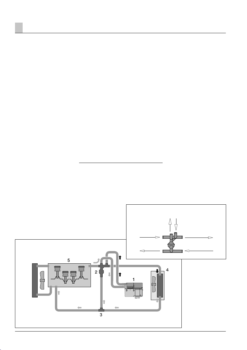
Integrate the heater and combination valve with
thermostat function in the cooling water circuit
Using the combination valve with 5 connections
Order No. 25 2014 80 72 00
If the water flow line and water return line from the
vehicle engine to the heat exchanger are laid separately in the engine compartment, the combination valve
with 5 connections and an additional T-piece must be
used.
Using the combination valve with 6 connections
Order No. 25 2014 80 62 00
If the water flow line and water return line from the
vehicle engine to the heat exchanger are laid in parallel in the engine compartment, the combination valve
with 6 connections (without T-piece) must be used.
Install combination valve with 5 connections
Cut the water flow hose from the vehicle engine to the
vehicle’s heat exchanger and insert the combination
valve. Cut the water return hose from the heat exchanger to the vehicle engine and insert the T-piece.
Use water hoses to connect the heater to the combination valve and T-piece – as shown in the sketch.
Heating characteristics in parking heater mode
Small cooling water circuit with heat discharge in the
vehicle interior
Initially, up to a cooling water temperature of approx.
67 °C, the heater’s heat is fed to the heat exchanger
only – fast heating of the inside of the vehicle.
Small cooling water circuit with heat discharge to the
vehicle engine
From a cooling water temperature of approx 67 °C,
part of the heater’s heat is also passed to the vehicle’s
engine. This causes slow heating of the engine circuit,
without rapid cooling of the “small cooling water circuit” for interior heating.
Heating characteristics in auxiliary heater mode
Large cooling water circuit
While the vehicle’s engine is running the heat is uniformly distributed between the heat exchanger and the
vehicle engine – further shortening of the heating up
phase and heating of the inside of the vehicle.
Install combination valve with 6 connections
Cut the water flow hose and the water return hose
from the vehicle engine to the vehicle’s heat exchanger
and insert the combination valve. Use water hoses to
connect the heater to the combination valve – as
shown in the sketch.
Combination valve with thermostat function (6 connections)
Heater
from
vehicle engine
to the
vehicle engine
to the
vehicle heat exchanger
from
vehicle heat exchanger
1 Heater
2 Combination valve
(5 connections)
3 T-piece
4 Heat exchanger
5 Vehicle engine
18
Page 19

Installation
3
Exhaust system
(For exhaust system diagram see page 23)
Mounting the exhaust system
The universal installation kit includes a flexible exhaust
pipe, inner Ø 24 mm, 1000 mm long and an exhaust
silencer.
The flexible exhaust pipe can be shortened to 20 cm or
lengthened to max. 2 m, depending on the installation
conditions.
Fasten the exhaust silencer to a suitable position in the
vehicle.
Lay the flexible exhaust pipe from the heater to the
exhaust silencer and fasten with pipe clips.
Fix a short exhaust pipe end (with end sleeve) to the
exhaust silencer with a pipe clip.
Caution!
Safety instructions!
The whole exhaust system gets very hot while the
heater is running and immediately afterwards.
This is why the exhaust system must be routed according to these installation instructions.
• The exhaust outlet must end in the open air.
• The exhaust pipe may not protrude beyond the lateral
limits of the vehicle.
• Install the exhaust pipe sloping slightly downwards. If
necessary, make a drain hole with an approx. Ø of
5 mm at the lowest point as a condensation outlet.
• Important functional parts of the vehicle may not be
impaired (maintain sufficient clearance).
• Mount the exhaust pipe with sufficient clearance to
heat-sensitive parts. Pay particular attention to fuel
pipes (made of plastic or metal), electrical cables and
brake hoses etc.!
• Exhaust pipes must be securely fixed (recommended
clearance of 50 cm) to avoid damage due to
vibrations.
• Lay the exhaust system so that the outflowing
exhaust gases are not sucked in as combustion air.
• The mouth of the exhaust pipe must not become
clogged with dirt and snow.
• The mouth of the exhaust pipe must not point in the
direction of travel.
• Always fix the exhaust silencer to the vehicle.
Danger!
Risk of injuries and burns!
Every type of combustion produces high temperatures
and toxic exhaust fumes.
This is why the exhaust system must be routed according to these installation instructions.
• Do not perform any work on the exhaust system while
the heater is working.
• Before working on the exhaust system, switch off the
heater first and wait until all the parts have
completely cooled down, wear safety gloves if
necessary.
• Do not inhale exhaust fumes.
Please note!
• Comply with the regulations and safety instructions for
this chapter given on page 4 – 7.
• The exhaust pipe end should be much shorter than
the flexible exhaust pipe from the heater to the
exhaust silencer.
19
Page 20
Installation
3
Combustion air system
Installing the combustion air system
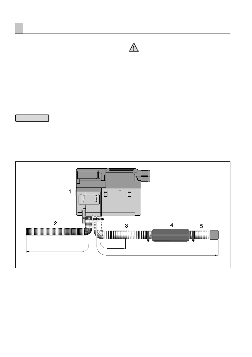
The heater – as described in these installation instructions – is installed in the engine compartment. It is not
necessary to install a combustion air hose if the intake
connection for the combustion air is in an area in
which the combustion air does not get hotter than
25 °C and in which neither spray water or dust / dirt
are to be expected. Otherwise, a flexible combustion
air hose, inner Ø 20 mm up to 1.5 m long must be
installed in order to take the combustion air from an
area which fulfils the conditions named above.
Please note!
Comply with the regulations and safety instructions for
this chapter given on page 4 – 7.
Caution!
Safety instructions for the combustion air system!
• The combustion air opening must be free at all times.
• Lay the combustion air intake to ensure that exhaust
fumes cannot be sucked in as combustion air.
• Arrange the combustion air intake so that it is not
directed against the wind blast or airstream.
• Do not allow the combustion air intake to become
clogged with dirt and snow.
• Install the combustion air intake system sloping
slightly downwards. If necessary, make a drain hole
approx. Ø 5 mm at the lowest point to drain off
condensation.
max. 1.5 m
1 Heater
2 Combustion air hose
3 Exhaust pipe
4 Exhaust silencer
5 Exhaust pipe end with end sleeve
20
min. 20 cm
max. 2 m
Page 21
Installation
3
Fuel supply
Installing the metering pump, laying the fuel pipes
and installing the fuel tank
The following safety instructions must always be observed when installing the metering pump, laying the
fuel pipes and installing the fuel tank.
Deviations from the instructions stated here are not
allowed.
Failure to comply can result in malfunctions.
Danger!
Risk of fire, explosion, poisoning and injuries!
Caution when handling fuel.
• Switch off the vehicle engine and the heater before
refuelling and before working on the fuel supply.
• Avoid naked flames when handling fuel.
• Do not smoke.
• Do not inhale petrol fumes.
• Avoid contact with the skin.
Caution!
Safety instructions for laying the fuel pipes!
• Use a sharp knife only to cut fuel hoses and pipes to
length. Interfaces must not be crushed and must be
free of burrs.
• Wherever possible, lay the fuel pipes from the
metering pump to the heater with with a continuous
rise.
• Fuel pipes must be securely fixed to avoid damage
and / or noise due to vibrations (recommended
guideline value: clearance of around 50 cm).
• Fuel pipes must be protected against mechanical
damage.
• Route the fuel pipes so that any distortion of the
vehicle, engine movements etc. cannot have any
lasting effect on the service life.
• Parts carrying fuel must be protected from interfering
heat.
• Never route or fasten the fuel lines to the heater or
vehicle exhaust system. When systems cross, always
ensure there is a sufficient heat clearance. If
necessary, attach heat deflection plates.
• Dripping or evaporating fuel must never be allowed to
collect on hot parts or ignite on electric systems.
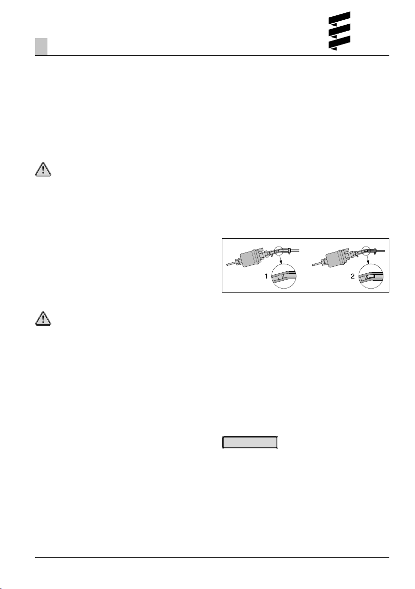
• When connecting fuel pipes with a fuel hose, always
install the fuel pipes with a butt joint to prevent any
bubbles from forming.
1 Correctly laid lines
2 Incorrectly laid lines – bubbles form
Safety instructions for fuel pipes and fuel tanks in
buses and coaches
• In buses and coaches, fuel lines and fuel tanks may
not be routed through the passenger compartment or
driver’s cab.
• Fuel tanks in buses and coaches must be positioned
in such a way that the exits are not in immediate
danger if a fire occurs.
Please note!
Comply with the regulations and safety instructions for
this chapter given on page 4 – 7.
21
Page 22
Installation
3
Fuel supply for 12 volt heaters
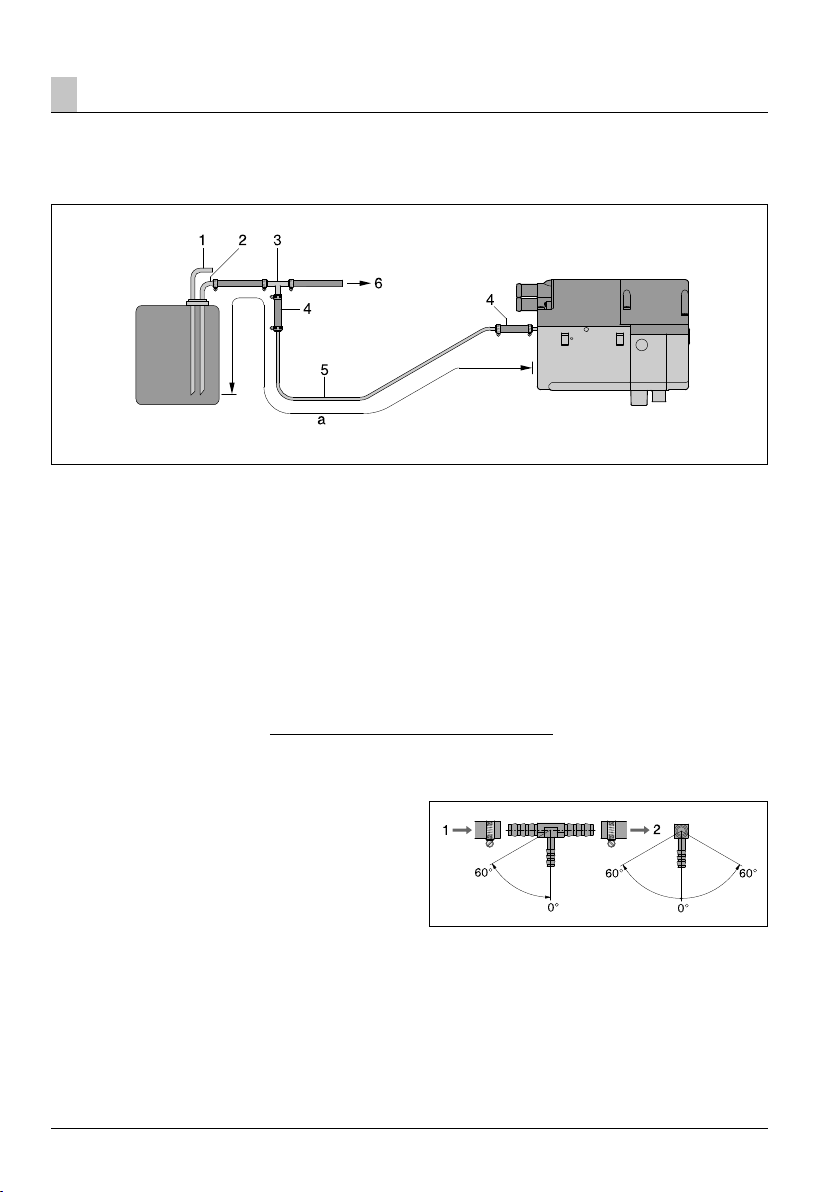
Fuel extraction using a T-piece from the fuel flow line, from the tank fitting
to the vehicle engine
1 Fuel return pipe from tank connection
2 Fuel flow line from tank connection –
insert T-piece in the fuel flow line upstream of the
fuel pump.
3 T-piece
4 Fuel hose, 3.5 x 3 (di = Ø 3.5 mm),
approx. 50 mm long
5 Fuel hose, 4 x 1 (di = Ø 2 mm)
6 To the vehicle engine, mechanical fuel or injection
pump.
Installation position of the T-piece
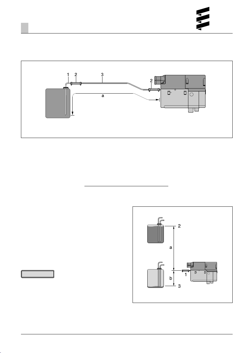
Install any T-piece in the same installation positions
shown in the diagram.
Allowable pipe length
Intake side
a = max. 5 m
1 Direction of flow – from the fuel tank
2 Direction of flow – to the vehicle engine
22
Page 23
Installation
3
Fuel supply for 12 volt heaters
Fuel feed point with tank connection riser pipe,
installed in the tank fitting
1 Tank connection for tank fitting,
di = Ø 2 mm, da = Ø 4 mm
2 Fuel hose, 3.5 x 3 (di = Ø 3.5 mm),
approx. 50 mm long
3 Fuel hose, 4 x 1 (di = Ø 2 mm)
Permissible suction and pressure head
Pressure head from vehicle tank to the heater:
a = max. 3000 mm
Suction head in pressure-less vehicle tank:
b = max. 1000 mm
Suction head in a vehicle tank in which negative pressure occurs during extraction (valve with 0.03 bar in
the tank cap):
b = max. 400 mm
Please note!
Check tank ventilation.
Allowable pipe length
Intake side:
a = max. 5 m
1 Connection at the heater
2 Max. fuel level
3 Min. fuel level
23
Page 24
Installation
3
Fuel supply for 24 volt heaters
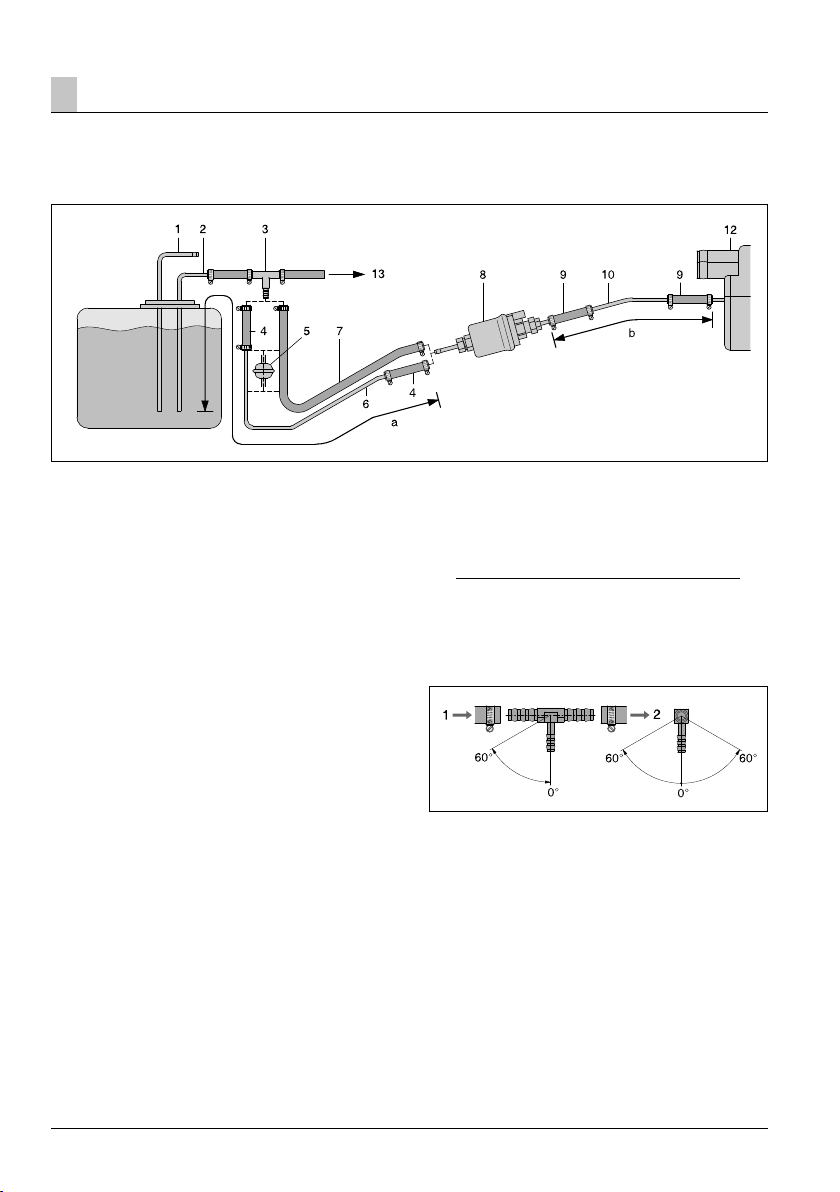
Fuel extraction using a T-piece from the fuel flow line, from the tank fitting
to the vehicle engine
1 Return line
2 Flow line from the tank fitting to the vehicle
engine – insert T-piece in the flow line upstream of
the fuel pump
3 T-piece
4 Fuel hose, 5 x 3 (di = Ø 5 mm), approx. 50 mm
long
5 Fuel filter – required for contaminated fuel only
6 Fuel hose, 6 x 2 (di = Ø 2 mm)
7 Fuel hose, 5 x 3 (di = Ø 5 mm)
8 Metering pump
9 Fuel hose, 3.5 x 3 (di = Ø 3.5 mm),
approx. 50 mm long
10* Fuel hose, 4 x 1.25 (di = Ø 1.5 mm)
11 Fuel hose, 4 x 1 (di = Ø 2 mm)
12 Heater
13 To the vehicle engine, mechanical fuel or injection
pump
* For diesel heaters, if necessary, a fuel pipe, 4 x 1
(di = Ø 2 mm) can also be used for the fuel pipe,
4 x 1.25 (di = Ø 1.5 mm), Item (10).
The pipe length details remain unchanged.
The fuel pipe, 4 x 1 must be ordered separately,
please refer to the spare parts list or additional
parts catalogue for the Order No.
Permissible pipe lengths
Intake side Delivery side
a = max. 5 m b = max. 6 m
Installation position of the T-piece
Install any T-piece in the same installation positions
shown in the diagram.
1 Direction of flow – from the fuel tank
2 Direction of flow – to the vehicle engine
24
Page 25
Installation
3
Fuel supply for 24 volt heaters
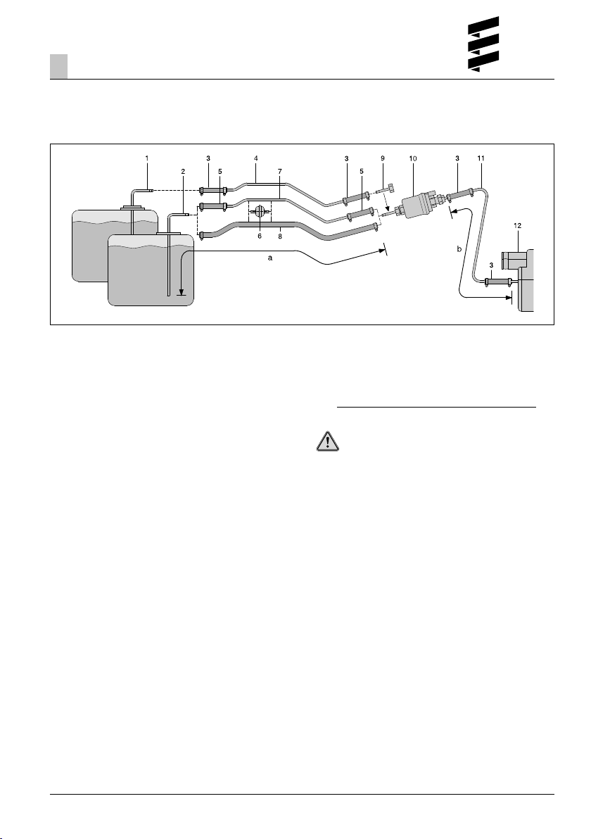
Fuel feed point with tank connection riser pipe,
installed in the tank fitting
1 Tank connection for tank fitting, di = Ø 2 mm,
da = Ø 4 mm, Order No. 20 1645 89 35 00
2 Tank connection for metal tank, di = Ø 2 mm,
da = Ø 6 mm, Order No. 25 1226 89 50 00
3 Fuel hose, 3.5 x 3 (di = Ø 3.5 mm),
approx. 50 mm long
4 Fuel hose, 4 x 1 (di = Ø 2 mm)
5 Fuel hose, 5 x 3 (di = Ø 5 mm), approx. 50 mm
long
6 Fuel filter – required for contaminated fuel only
7 Fuel hose, 6 x 2 (di = Ø 2 mm)
8 Fuel hose, 5 x 3 (di = Ø 5 mm)
9 Connection fitting, da = 4 mm
10 Metering pump
11* Fuel hose, 4 x 1.25 (di = Ø 1.5 mm)
12 Heater
* For diesel heaters, if necessary, a fuel pipe, 4 x 1
(di = Ø 2 mm) can also be used for the fuel pipe,
4 x 1.25 (di = Ø 1.5 mm), Item (11).
The pipe length details remain unchanged.
The fuel pipe, 4 x 1 must be ordered separately,
please refer to the spare parts list or additional
parts catalogue for the Order No.
Permissible pipe lengths
Intake side Delivery side
a = max. 5 m b = max. 6 m
Caution!
Safety instructions for the fuel supply
• The fuel may not be discharged by means of gravity or
overpressure in the fuel container.
• It is not permitted to extract fuel downstream of the
vehicle’s own fuel pump.
• If the pressure in the fuel line is more than 0.2 bar up
to max. 4.0 bar, use a pressure reducer
(Order No. 22 1000 20 08 00) or a separate tank
connection.
• If the pressure in the fuel pipe is over 4.0 bar or if
there is a non-return valve in the return pipe (in the
tank), a separate tank connection must be used.
• If using a T-piece in a plastic pipe, always insert
support sleeves in the plastic pipe. Connect the
T-piece and the plastic pipe with the relevant fuel
hoses and secure with hose clips.
25
Page 26
Installation
3
Fuel supply
for 24 V heaters
Installation position of the metering pump
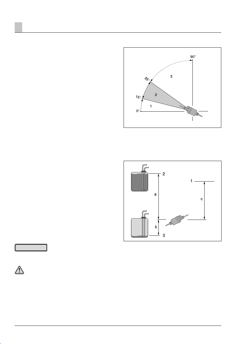
Always install the metering pump with the delivery side
rising upwards. Any mounting position over 15° is
allowed, although a mounting position between 15°
and 35° is preferable.
Permissible suction and pressure head of the
metering pump
Pressure head from vehicle tank to metering pump:
a = max. 3000 mm
Suction head in pressure-less vehicle tank:
b = max. 1000 mm
Suction head in a vehicle tank in which negative pressure occurs during extraction (valve with 0.03 bar in
the tank cap):
b = max. 400 mm
Pressure head from the metering pump to the heater:
c = max. 2000 mm
1 Installation position within range 0° – 15° is not
allowed
2 Preferred installation position within range 15° – 35°
3 Installation position within range 35° – 90° is
allowed
Please note!
Check tank ventilation.
Caution!
Safety instructions for installing the metering pump!
• Always install the metering pump with the delivery
side rising upwards – minimum angle 15°.
• Protect the metering pump and filter from impermissible heating, do not install near to silencers and
exhaust pipes.
26
1 Connection at the heater
2 Max. fuel level
3 Min. fuel level
Page 27
Installation
3
Fuel supply
Fuel quality for diesel heaters
The heater runs problem-free on standard commercial
quality fuel in accordance with DIN EN 590, which you
use to run your vehicle engine.
Fuel for special cases
In special cases the heater can also be run on heating
oil (above 0 °C) or kerosene / paraffin oil.
Fuel for low temperatures
Refineries and fuel service stations automatically adjust
the fuel to normal winter temperatures (winter diesel).
This means that difficulties can only arise if there is an
extreme drop in temperature, as is the case for the
vehicle engine too. Please also refer to the vehicle
manual.
If the heater is run from a separate tank, please comply
with the following rules: For temperatures above 0 °C,
any kind of diesel fuel as per DIN EN 590 can be used.
If no special diesel fuel is available for low temperatures, then paraffin or petrol should be mixed with the
fuel according to the following table:
Temperature Winter diesel Additive
0 °C to –25 °C 100 % –
–25 °C to –40 °C 50 %* 50 % kerosene
or petrol
* or 100 % special cold diesel fuel (Arctic diesel)
Please note!
• Additions of used oil are not allowed!
• After refuelling with winter or cold diesel or the listed
blends, the fuel lines and the metering pump must be
filled with the new fuel by letting the heater run for 15
minutes!
Operation with biodiesel
(FAME for diesel engines according to DIN EN 14 214)
Hydronic D 5 W SC – 24 volt
The heater is approved for operation with biodiesel up
to a temperature of –8° C (the flowability reduces at
temperatures below 0 °C).
Please note!
• When using 100 % biodiesel, the heater should be
operated twice a year with diesel fuel (in the middle
and at the end of a heating period) to burn off any
possibly accumulated biodiesel residues.
To do so, let the vehicle tank run almost empty and
fill with diesel fuel without adding any biodiesel. While
running on this tank filling, switch the heater on 2 to
3 times for 30 minutes at a time at the highest
temperature setting.
• When operating with diesel / biodiesel mixtures of up
to 50 % biodiesel, intermediate operation with pure
diesel fuel is not necessary.
Hydronic D 4 W SC – 12 volt and
Hydronic D 5 W SC – 12 volt
are not approved for running on biodiesel. The addition
of up to 10 % biodiesel is allowed.
27
Page 28

Operation and function
4
Operating instructions
The heater is operated by a control unit. Detailed
operating instructions are supplied with the control
unit.
Please note!
You will be issued the operating instructions by the
installation workshop.
Important instructions for operation
Safety checks before starting up the heater
After a lengthy stoppage (summer months), check all
components for secure fit (tighten screws where
necessary).
Carry out a visual check of the fuel system for leaks.
Before switching on
Before switching on or pre-programming heating mode,
switch the vehicle’s heating lever to “WARM” (maximum
setting) and the blower to “slow level” (low electricity
consumption). In vehicles with automatic heating,
before switching off the ignition, switch the heating
lever to “MAX” and the required damper position to
“OPEN”.
Parking / cab ventilation with “heat / ventilate”
changeover switch
Parking / cab ventilation means: possible activation of
the vehicle blower directly via the heater’s preselection
timer or – even more useful – via the EasyStart R/R
radio remote control by bypassing heating mode, in
order to ventilate the often over-heated vehicle interior
with fresh air just before driving away (separate wiring).
Heating at high altitudes
When using the heater at high altitudes, please note:
• Heating at altitudes up to 1500 m:
• Unlimited heating possible.
• Heating at altitudes over 1500 m:
• You can use the heater at this altitude for short
periods (e.g. driving through a mountain pass or
taking a break in your journey).
– for longer stays, e.g. winter camping, it is
necessary to adjust the fuel supply to the altitude,
please contact a JE partner for further details and
advice.
Please note!
The installation of an altitude kit (Order No. 22 1000
33 22 00) enables diesel heaters to be operated at
altitudes over 1500 m, even for lengthy stays.
Initial commissioning of the heater
The following points are to be checked by the company
installing the heater during initial commissioning.
• After installation of the heater, the coolant circuit and
the whole fuel supply system must be vented carefully.
Comply with the instructions issued by the vehicle
manufacturer.
• Open the coolant circuit before the trial run (set the
temperature control to “WARM”).
• During the heater trial run, all water and fuel
connections must be checked for leaks and secure,
tight fit.
• If faults occur while the heater is running, use a
diagnostic unit to determine and correct the cause of
the fault.
Functional description
Switching on (parking heater mode)
When the heater is switched on, the operating display
in the control unit lights up. The water pump starts up.
After a defined program run, the combustion air fan,
glow plug and metering pump start and start up the
combustion. Once a stable flame has formed, the glow
plug switches off under time control.
Heating mode
Depending on the heat requirements, the heater runs
at the following levels:
HIGH – LOW – OFF (pause mode).
The temperature thresholds are permanently programmed in the electronic control box. If the heating
requirement in the “LOW” stage is so small that the
cooling water temperature reaches 85 °C, the heater
controls in pause mode. An after-run of approx. 120
seconds follows, the heater then switches off (pause
mode). The control lamp lights up and the water pump
continues running, even in pause mode.
Please note!
Depending on the connection, the heater can be operated as a parking heater or as a combined parking and
auxiliary heater to compensate for insufficient heat
output from the vehicle engine (for details of wiring, see
circuit diagram).
28
Page 29
Operation and function
4
Control and safety devices
• If the heater does not ignite within 90 seconds after
the fuel starts to pump, the start is repeated. If the
heater still does not ignite after another 90 seconds
of fuel being pumped, the heater is automatically shut
down. After an impermissible number of failed start
attempts, the controller is locked.*
• If the flame goes off by itself during operation, the
heater is restarted. If the heater still does not ignite
within 90 seconds after the fuel pump has been
restarted, or ignites and but goes off again within 15
minutes, a safety lock-out occurs. The shutdown on
faults can be cancelled by briefly switching off and on
again.
• In the event of overheating (e.g. water shortage,
poorly ventilated cooling water circuit), the
overheating sensor triggers, the fuel feed is
interrupted and the heater is automatically shut
down. Once the cause of the overheating has been
eliminated, the heater can be re-started by switching
it off and on again (provided that the heater has
sufficiently cooled, cooling water temperature
< 70 ° C). After the heater has been shut down due
to overheating an unacceptable number of times, the
control box is locked*.
• If the lower or upper voltage limit is reached, the
heater is automatically shut down.
• The heater does not start up if the glow plug is
defective or if the electric cable to the metering pump
is interrupted.
• The speed of the blower motor is continuously
monitored. If the blower motor does not start up, if it
is blocked or if the speed falls below 40 % of the
desired speed, the heater is automatically shut down
after 60 sec.
Please note!
Do not repeat the switching off / on routine more than
twice.
Emergency shutdown – EMERGENCY OFF
If an emergency shutdown – EMERGENCY OFF – is
necessary during operation, proceed as follows:
• Switch the heater off at the control unit or
• Remove the fuse or
• Disconnect the heater from the battery.
* Cancellation of the lock or reading out errors is
possible:
• with the module timer / EasyStart T timer
• with the radio remote control TP5 / EasyStart R+.
For other control units by connecting:
• the diagnostic unit
• the customer service program KD2000 / EDiTH.
For operation and fault list, please refer to the
enclosed operating instructions or the troubleshooting
and repair instructions for the heater.
29
Page 30
Electrics
5
Heater wiring
Caution!
Safety instructions!
The heater is to be connected up electrically according
to the EMC directives. EMC can be affected if the heater is not connected up correctly. For this reason, comply with the following instructions:
• Ensure that the insulation of electrical cables is not
damages. Avoid: chafing, kinking, jamming or
exposure to heat.
• Seal any connector chambers of watertight
connectors not in use with filler plugs to ensure they
are dirt-proof and water-proof.
• Electrical connections and ground connections must
be free of corrosion and firmly connected.
• Lubricate connections and ground connections
outside the heater interior with contact grease.
Please note!
Comply with the following when wiring the heater and
the control unit:
• Electrical leads, switch and control gear must be
positioned in the vehicle so that they can function
perfectly under normal operating conditions without
impairment (e.g. due to heat exposure, moisture,
etc.).
• The following cable cross sections are to be used
between the battery and heater. This ensures that
the max. permissible voltage drop in the cables does
not exceed 0.5 V for 12 V or 1 V for 24 V rated
voltage.
Cable cross-sections for a cable length (plus cable +
minus cable) of:
– up to 5 m = cable cross-section 4 mm
– from 5 m to 8 m = cable cross-section 6 mm
• If the positive cable is to be connected to the fuse
box (e.g. terminal 30), the vehicle’s cable from the
battery to the fuse box must also be included in the
calculation for the total cable length and redimensioned if necessary.
• Insulate unused cable ends.
2
2
30
Page 31

Electrics5
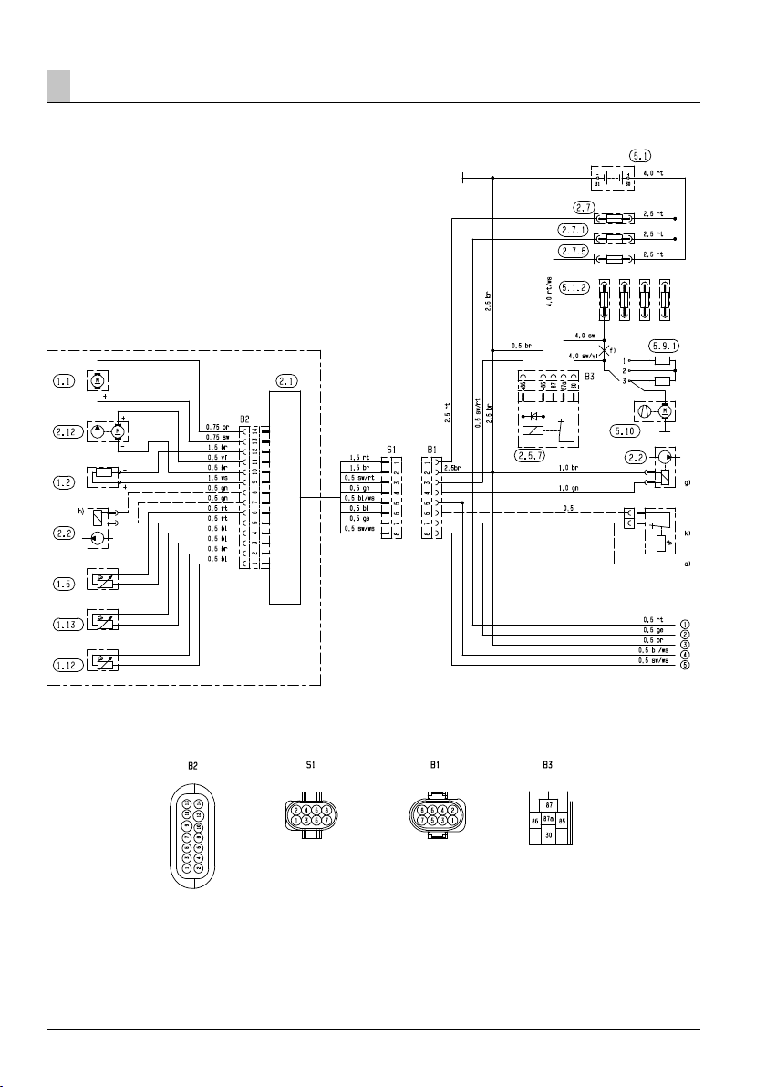
Parts list for circuit diagram, 12 volt heater
1.1 Burner motor
1.2 Glow plug
1.5 Overheating sensor
1.12 Flame sensor
1.13 Temperature sensor
2.1 Control box
2.2 Fuel metering pump
2.5.7 Relay, vehicle blower
2.7 Main fuse, 20 A
2.7.1 Fuse, activation 5 A
2.7.5 Fuse, vehicle blower 25 A
2.12 Water pump
5.1 Battery
5.1.2 Fuse block in the vehicle
5.9.1 Switch, vehicle blower
5.10 Vehicle blower
a) For auxiliary heating option, connect to D+
f) Disconnect cable
g) For petrol only
g) For diesel only
k) Switch (auxiliary heating, e.g. outside
temperature
< 5 °C or summer / winter changeover)
Cable colours circuit diagrams
sw = black
ws = white
rt = red
ge = yellow
gn = green
vi = violet
br = brown
gr = grey
bl = blue
li = purple
Connectors and bush housings are shown from the
cable inlet side.
Please note!
See page 32 for circuit diagram.
31
Page 32
Electrics533Electrics5
Circuit diagram, 12 volt heater
See page 31 for parts list 25 1920 00 96 01 D
32
Page 33

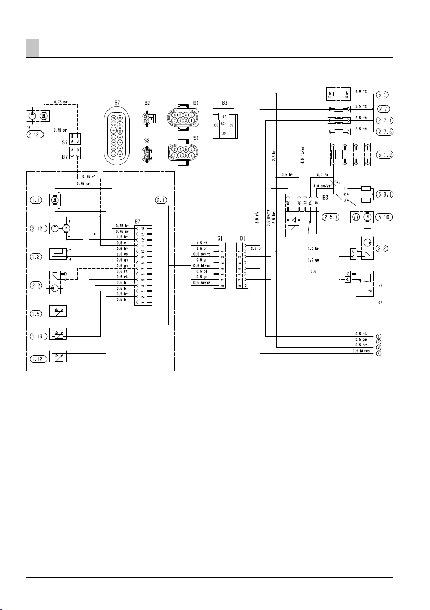
Parts list for circuit diagrams, 24 volt
heater and 24 volt heater, ADR mode
1.1 Burner motor
1.2 Glow plug
1.5 Overheating sensor
1.12 Flame sensor
1.13 Temperature sensor
2.1 Control box
2.2 Fuel metering pump
2.7 Main fuse, 15 A
2.7.1 Fuse, activation 5 A
2.12 Water pump
5.1 Battery
5.2.1 Battery main switch m)
(operation, e.g. controlled by the ignition lock)
5.2.2 Battery isolating switch m)
(Emergency Off function for ADR / ADR99)
a) For auxiliary heating option, connect to D+
d) Auxiliary drive input for TRS devices
f) Disconnect cable
h) Water pump, external
k) Switch, auxiliary heating (e.g. outside
temperature < 5 °C or summer / winter
changeover)
m) If only one switching element is used for items
5.2.1 and 5.2.2, it is important to ensure that
on activating the „open the battery isolating
switch“ function (Emergency OFF function for
ADR / ADR99), the switch always breaks
contact immediately (regardless of the heater
condition) and all the heater’s circuits are
disconnected from the battery.
“Positive” length + “Negative” length:
– 5 m: Cross-section 4 mm
– 5 m – 8 m: Cross-section 6 mm
2
2
Insulate unused cable ends.
Connectors and bush housings are shown from the
cable inlet side.
Cable colours
sw = black
ws = white
rt = red
ge = yellow
gn = green
vi = violet
br = brown
gr = grey
bl = blue
li = purple
Please note!
For circuit diagrams, see page 34 and 35
Page 34
Electrics5
Circuit diagram, 24 volt heater
25 2147 00 96 01 DSee page 33 for parts list
34
Page 35
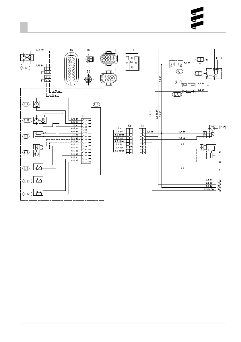
Electrics5
Circuit diagram, 24 volt heater, ADR mode
25 2147 00 97 01 CSee page 33 for parts list
35
Page 36

Electrics5
Parts list for circuit diagram, EasyStart R+
/ R / T and EasyStart T – ADR control units
2.15.1 Room temperature sensor
(with EasyStart R+ included in scope of supply,
with EasyStart T and EasyStart R optional)
2.15.9 Temperature sensor (outside temperature)
(optional)
3.1.7 “ON / OFF” button (optional)
3.1.9 “heat / ventilate” switch (optional)
3.1.16 Radio remote control button
3.2.15 EasyStart T timer
3.3.9 EasyStart R radio remote control (stationary
unit)
3.3.10 EasyStart R+ radio remote control (stationary
unit)
3.6.1 Lead harness
3.8.3 Antenna
c) Terminal 58 (lighting)
d) Parking / cab ventilation with vehicle blower
(optional)
e) EasyStart T timer connection
g) External “ON / OFF” button (optional)
Cable colours circuit diagrams
sw = black
ws = white
rt = red
ge = yellow
gn = green
vi = violet
br = brown
gr = grey
bl = blue
li = purple
Connectors and bush housings are shown from the
cable inlet side.
Please note!
For circuit diagrams, see page 37 – 40.
36
Page 37
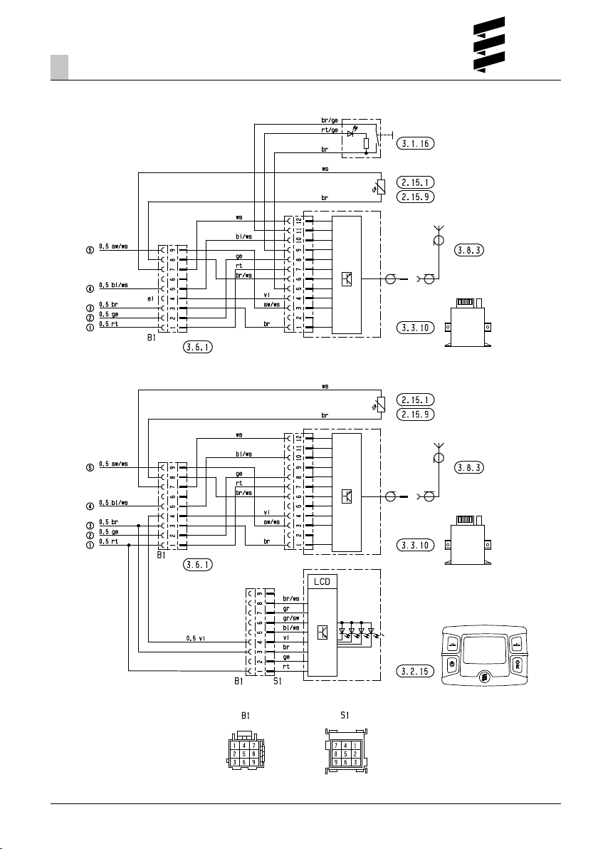
Electrics5
Circuit diagram for EasyStart R+ control unit
25 2217 00 97 01 CSee page 36 for parts list
37
Page 38
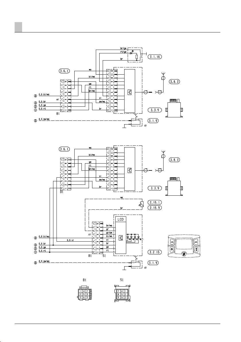
Electrics5
Circuit diagram for EasyStart R control unit
See page 36 for parts list
38
25 2217 00 97 02 B
Page 39
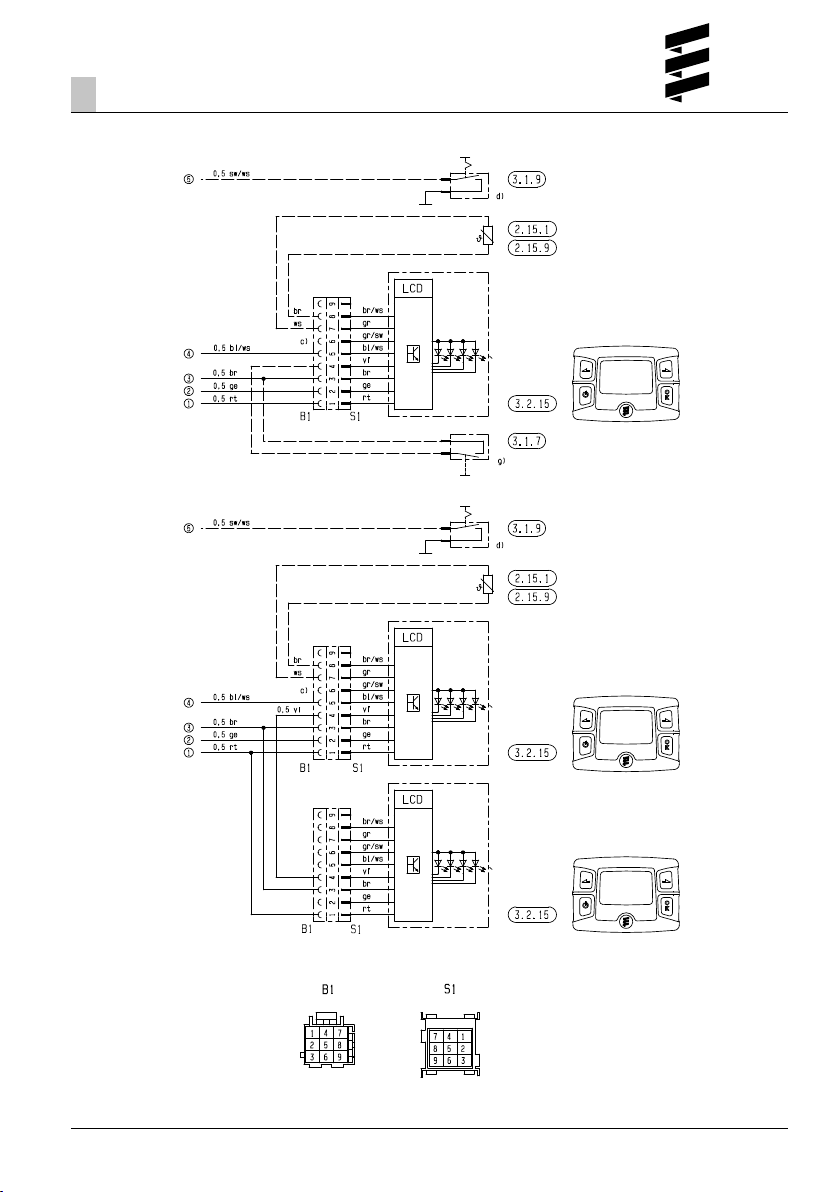
Electrics5
Circuit diagram for EasyStart T control unit
See page 36 for parts list 25 2217 00 97 03 A
39
Page 40
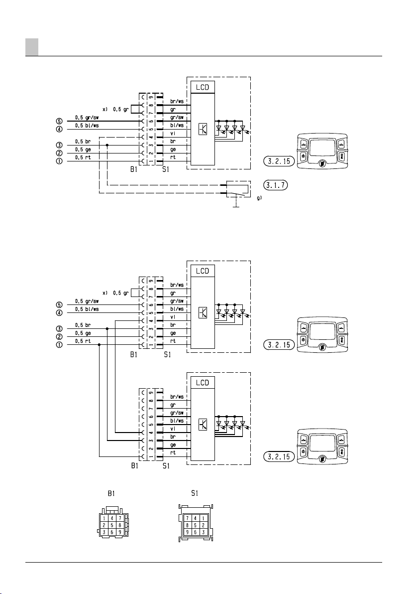
Electrics5
Circuit diagram for EasyStart T – ADR control unit
See page 36 for parts list 25 2218 00 97 01 A
40
Page 41

Troubleshooting / maintenance / service
6
If any faults occur, please check the
following items
• If the heater does not start after being switched on:
– Switch the heater off and on again.
• If the heater still does not start, check whether:
– Fuel in the tank?
– The fuses are ok?
– The electrical cables, connections, terminals, are
ok?
– The hot air, combustion air or exhaust systems are
blocked?
Troubleshooting
If, after checking these items, the heater is still faulty or
another malfunction occurs in your heater, please
contact:
• If factory-installed, your contract workshop / garage.
• If subsequently installed, the workshop / garage
which installed the heater.
Please note!
Please note that guarantee claims can expire if the
heater is modified by a third party or if non-original
parts are installed.
Maintenance instructions
• Switch the heater on once a month for about 10
minutes, even outside the heating period.
• Before the heating period starts, the heater should
undergo a trial run. If thick, persistent smoke
develops, unusual burning noises or a clear fuel smell
occurs or if electric / electronic parts overheat, the
heater must be switched off and put out of service by
removing the fuse. In this case, the heater should not
be started up again until it has been checked by
qualified staff who have been trained on Eberspächer
heaters.
• Check the openings of the combustion air supply and
exhaust system after longer standstill periods, clean if
necessary!
Service
If you have any technical queries or problems with your
pre-heater, dial the following service phone number
from within Germany:
Hotline
Tel. 0800 / 12 34 300
Fax hotline
Tel. 01805 / 26 26 24
Outside of Germany, please contact the respective
Eberspächer national representative.
41
Page 42

Environment
7
Certification
The high quality of Eberspächer’s products is the key to
our success. To guarantee this quality, we have organised all work processes in the company along the lines
of quality management (QM). Even so, we still pursue a
large number of activities for continuous improvement of
product quality in order to keep pace with the similarly
constantly growing requirements made by our customers.
All the steps necessary for quality assurance are stipulated in international standards.
This quality is to be considered in a total sense.
It affects products, procedures and customer / supplier
relationships.
Officially approved public experts assess the system and
the corresponding certification company awards a
certificate.
Eberspächer has already qualified for the following
standards:
Quality management as per DIN EN ISO 9001:2000
and ISO/TS 16949:1999
Environment management system as per DIN EN
ISO 14001:1996
Disposal
Disposal of materials
Old devices, defect components and packaging material can all be separated and sorted into pure-grade
factions so that all parts can be disposed of as required
in an environment-friendly manner recycled where
applicable.
Electric motors, control boxes and sensors (e.g. temperature sensors) are deemed to be “electronic scrap”.
Dismantling the heater
The heater is dismantled according to the repair stages
in the current troubleshooting / repair instructions.
Packaging
The packaging of the heater can be kept in case it has
to be sent back.
EC Declaration of Conformity
With regard to the product named in the following
Hydronic heater type
we herewith confirm that it conforms with the prime
safety requirements stipulated in the directives of the
EU Council for harmonisation of the legal regulations of
the member states with regard to electromagnetic
compatibility (89 / 336 / EEC).
This declaration applies to all heaters produced according to the Hydronic production drawings – which
are an integral part of this declaration.
The following standards / directives have been used to
assess the product with regard to electromagnetic
compatibility:
• EN 50081 – 1 Basic form interference emission
• EN 50082 – 1 Basic form of interference immunity
• 72 / 245 / EEC – Modification status 2005 / 83 / EC
interference suppression in motor vehicles.
42
Page 43

Lists
8
List of abbreviations
ADR
European agreement about the international transport
of dangerous goods on the road.
EC type-approval
Permit awarded by the Federal Vehicle Office for the
production of a heater for installation in motorised
vehicles.
EMC directive
Electromagnetic compatibility.
JE-partner
J. Eberspächer partner.
FAME
FAME for diesel engines according to DIN EN 14 214.
43
Page 44

www.eberspaecher.com
J. Eberspächer
GmbH & Co. KG
Eberspächerstr. 24
D - 73730 Esslingen
Phone +49 711 939 - 00
Fax +49 711 939 - 0643
[email protected]
Subject to change without notice Pri nted in Germany © J. Eberspächer GmbH & Co. KG
 Loading...