

Hydro Mobile M2 Owner's Manual
Call us for information:
1-888-484-9376 (US)
(toll free in the United States)
450 589-8100 (Canada)
Owner’s Manual
11053005-0-00000-0
M2_OpMan_v5.02_EN
www.hydro-mobile.com
G
ENERAL INFORMATION
Model M2 Series 14' (4,3 m) motorized unit
M2 Series 24' (7,3 m) motorized unit
Motorized unit serial number
Manufacturing date
© 2015 by Hydro Mobile Inc. All rights reserved
This manual was produced by Hydro Mobile Inc. on Adobe® InDesign CS5.5® version 5.0.1 for Windows®.
Technical drawings were prepared using Autodesk Inventor ® 2012. Illustrations were created with Autodesk®
3ds Max®, Autodesk Inventor ® 2008, Adobe® Illustrator CS5.1 for Windows® and Adobe® Photoshop CS5.1®
for Windows®.
This manual may not, in whole or in part, be copied, photocopied, reproduced, translated, or converted to any
electronic or machine readable form without prior written consent of Hydro Mobile Inc.
APAVE certifi cation: 0077-5237-760-0411-4103 (2014)
125 de l’Industrie
L’Assomption, Quebec, Canada
J5W 2T9
NOTE
All assembly and operation instructions located on motorized units and bridges take precedence over
information contained in this manual. Should there be any discrepancies discovered throughout any
published documentation issued by Hydro Mobile or its authorized affi liates, the following order of
precedence shall prevail:
1. Written documents issued by the Hydro Mobile Engineering department
2. Recall instructions
3. Assembly or operation instructions displayed on the motorized unit
4. Owner's manual
Any use of one or several Hydro Mobile motorized units, with or without accessories, in such a
confi guration or manner as not explicitly described in this manual is not allowed without the permission
of Hydro Mobile Inc.
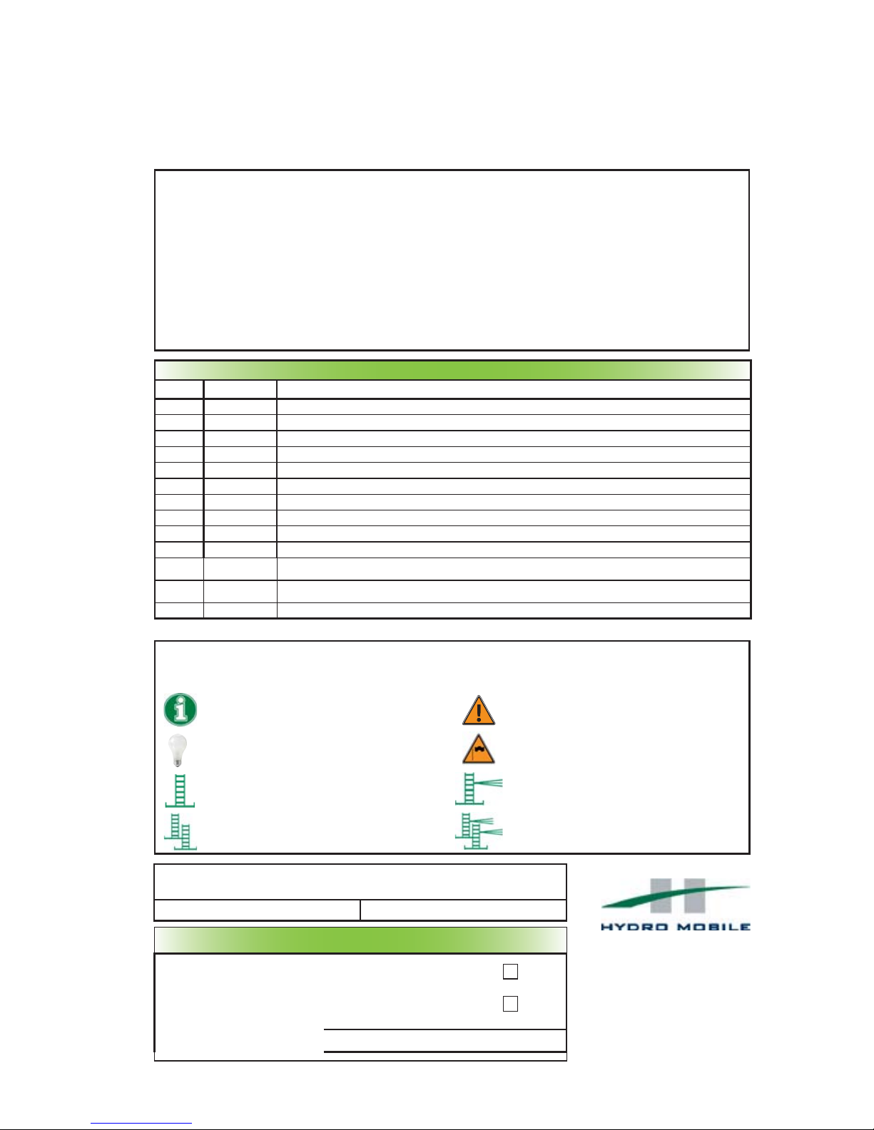
LEGEND OF ICONS
These icons are used to highlight important information throughout this manual
Information
Useful information for safe and easy operation
Warning note
An important warning: damage or injury may occur
Useful tip
A useful tip to facilitate installation or operation
Wind speed warning
An important warning: wind speed conditions
must be observed to avoid damage or injury
Type of setup
Single unit freestanding installation
Type of setup
Single unit installation with mast ties
Type of setup
Multiple units freestanding installation
Type of setup
Multiple units installation with mast ties
The information and instructions contained in this manual applies to
units bearing the following serial numbers
24M 5157 M2 and up 14M 0200 M2 and up
R
EVISION LIST
Version Date Description
v1.0 April 2002 First edition of Owner’s manual
v2.0 May 2002 Addition of forward extension and monorail
v2.1 June 2002 “Long” mast ties changed for “extensions”
v2.2 Sept 2002 Access and rest platforms
v3.0 Sept 2004 Addition of 14' (4,3 m) unit, split base and training sheets
v3.1 Sept 2004 Modifi cations to weights; various typographical corrections; modifi cation of grease type
v4.0 Sept 2010 Overall revision; inclusion of additional accessories; detailed warranty policy; inclusion of new modular bridge assemblies
v4.01 Oct 2010 Minor corrections
v4.02 Nov 2010 Modifi cations to load capacity charts; minor additions and corrections
v4.03 Oct 2015 Corrections to components included with shipped unit
v5.0 Feb/Mar 2016
Overall revision; major changes to installation instructions; inclusion of accessories (sidewalk canopy, mast base plates,
swivel bridge, fl ush bearing bridge adapter, multiple mast handler) (typo corrections in March before fi rst print)
v5.01 Sept 2016
Modifi cation to distance to wall in MU dimensions; modifi cation of number of plywoods required when cribbing;
modifi cations to bridge lengths in load capacities
v5.02 April 2017 Minor corrections; addition of storage instructions for unit and bridge
For orders or information:
1-888-484-9376 (US)
(toll free in the United States)
450 589-8100 (Canada)
11053005-0-00000-0

GENERAL INFORMATION
TABLE OF CONTENTS
Introduction .................................................................3
Warranty .................................................................4
Performance and safety rules......................................5
Defi nition of the competent person ...................5
Defi nition of the qualifi ed person ......................5
General guidelines ............................................5
Defi nition of standard installation ......................7
Overview .................................................................8
List of components included with shipped unit ............8
Specifi cations ............................................................10
Weight of components ...............................................12
Dimensions 13
Positioning
Minimum bearing surface capacities ..............15
Cribbing ..........................................................16
Setup and confi gurations
General guidelines ..........................................17
Combination of standard and non standard
confi gurations .................................................17
Defi nition of a standard confi guration .............17
Positioning of base outriggers ........................19
Installation of freestanding setups
Single unit ...................................................19
Multiple units ...............................................21
Installation of tied setups
Methods to install tie levels .........................22
“A” – progressive installation
Single unit ..............................................23
Multiples units ........................................24
“B” – pre-installation of tie levels
Single unit ..............................................25
Multiple units ..........................................27
“C” – pre-installation of tie levels
Single unit ..............................................28
Multiple units ..........................................30
Dismantling an installation
Safety guidelines .........................................32
Freestanding installations
Single unit .............................................32
Multiple units ..........................................32
Tied installations
Single unit (“A” or “B” installation) ................33
Multiple units (“A” or “B” installation) ............34
Single unit (“C” installation) ........................35
Multiple units (“C” installation).....................36
Lifting and moving a motorized unit setup ........37
Safety hooks system .................................................41
Fall protection equipment ..........................................41
Standard bridge
Overview .........................................................43
Bridge types...............................................................43
Cantilever bridge
Installation.......................................................43
Bearing bridge
Safety guidelines ............................................46
Installation.......................................................46
Offset bearing bridge structure ...................47
Safety chains ..............................................47
Dismantling a bearing bridge ..........................48
Multi purpose insert bridge (
MPI
)
Forward/Back extension bridge ......................49
Cantilever bridge.............................................50
Lateral cantilever bridge .................................50
Narrow bearing bridge ....................................51
Alternate bridge confi gurations ..................................53
Angled bearing bridge setup ...........................53
Inside / Outside corner bearing bridge............54
Swivel bridge
Installation of the square bridge adapter ........56
Installation of the swivel and square bridges ..57
Angle adjustment ............................................57
Standard and swivel bridge guardrails............58
Front cantilever confi gurations........................59
Counterweight adapter ...................................60
Motorized unit preparation instructions......................62
Engine startup preparation instructions .....................63
Storage of the control post ........................................64
Raising the platform...................................................65
Lowering the platform ................................................67
Installation of a mast section .....................................69
Installation of mast ties ..............................................70
Mast tie schedule ............................................70
Appropriate mast tie installation......................71
Mast tie requirements for
planking confi gurations ...................................72
Angle of mast ties and wall tie distances ........74
Passing mast tie levels ...................................75
Removal of mast ties ......................................75
Removal and transport of mast sections ........75
Angled mast ties .............................................76
Installation of the angle bracket ..................76
Installation of extended mast ties ................77
Anchoring system
Wall tie types ..................................................78
Installation of fl oor ties ....................................79
Installation of fi xed wall ties ............................79
Installation of a welded wall tie on a beam .......79
Installation of a re-usable wall tie....................79
Changes to the calculation method ...........................80
Load capacity calculation guidelines .........................80
Evenly distributed – Single unit setup
14' (4,3 m) motorized unit ...............................81
24' (7,3 m) motorized unit ...............................81
Evenly distributed – Multiple units setup
14' (4,3 m) motorized unit ...............................82
24' (7,3 m) motorized unit ...............................83
MPI – Evenly distributed with 24' (7,3 m) unit
Lateral cantilever ............................................84
Forward extension ..........................................85
Narrow bearing bridge ....................................86
Swivel bridge with 24' (7,3 m) unit
Single unit front 0-45 degrees.........................87
Single unit with counterweight adapter ...........88
Angled and corner installations
Inside corner ...................................................89
Outside corner ................................................90
Safety accessories
Guardrails
Standard .....................................................91
Face guardrail supports ..............................91
Plank-end guardrails ...................................92
Movable guardrails ......................................93
Universal plank safety support ....................93
Retractable rest platform .............................94
Other accessories
Outriggers ...........................................................
Planking confi guration guidelines ...............95
Outrigger selection table .............................95
Doubled outriggers ......................................96
Cross boxes ................................................97
Non standard planking confi gurations .........97
Top outriggers .............................................99
Bottom outriggers ........................................99
Cantilever outrigger supports ....................100
Sliding doors .................................................100
Wheel set ......................................................102
Hoist .............................................................103
Weather protection .......................................104
Monorail ........................................................108
Flush bearing bridge adapter ........................110
Securing the access walkway ....................... 111
Adapter base for sidewalk canopy
installation .....................................................112
Mast base plates...........................................115
Multiple mast handler....................................117
Transport and storage
Preparation of the motorized unit for
transport........................................................118
Storage of the control post............................119
Storage of the motorized unit........................119
Inspections and maintenance
Daily and weekly inspections and maintenance
Inspection and maintenance of
the cylinder hook .......................................120
Greasing the mast carriage and guide
rollers ........................................................121
Inspecting and greasing the
safety hooks ..............................................122
Frequent inspections and maintenance ........123
Annual inspections and maintenance ...........123
Examples of checklists .................................124
Hydraulic diagram .........................................125
General Information
General Information
Performance and Safety
Performance and Safety
1 – Motorized Unit
1 – Motorized Unit
3 – Bridges
3 – Bridges
4 – Power Pack and Operating Components
4 – Power Pack and Operating Components
6 – Load Capacities
6 – Load Capacities
7 – Accessories
7 – Accessories
2 – Safety Devices
2 – Safety Devices
8 – Transport, Storage and Maintenance
8 – Transport, Storage and Maintenance
5 – Masts and Mast Ties
5 – Masts and Mast Ties

GENERAL INFORMATION
Dear owner or user:
Thank you for investing in a Hydro Mobile M2 Series mast climbing work platform system
(24' / 7,3 m model or 14' / 4,3 m model). The design of these motorized units refl ects over
a decade of continued fi eld operation, testing and research work and comes as a solution
to our company’s deepest concern, your safety and well being on the job.
To ensure that the workplace becomes safer and more effi cient using a Hydro Mobile
system, always have appropriately trained personnel assemble, operate, dismantle and
move your mast climbing work platform system. These qualifi ed persons will be required
to read this owner’s manual and assimilate the information contained herein. Failure to do
so could lead to serious injury and/or equipment damage.
These motorized units were designed in accordance with the following standards:
US ANSI
A92.9-2011
, ISO 16369:2007 and EN 1495, 2006/42/CE “directive machine” and 89/336/CEE
“directive CEM”. Furthermore, these motorized units and the owner’s manual comply with
US ANSI A92.9-2011 standards, Federal Occupational Safety and Health Administration
Standards OSHA 29CFR1926 subpart L; with ISO 16369:2007 and CSA B354.5-07; and with
EN 1495, 2006/42/CE“directive machine”, 89/336/CEE “directive CEM” and ISO 16369:2007.
To maximize the life expectancy of your equipment and to enjoy years of trouble free
operation, we recommend that this Hydro Mobile system be serviced according to
maintenance schedules and recommendations provided in this manual. It is also advised
to refer to the Honda user’s manual included with the motorized unit.
Should you have any questions or concerns, please contact the nearest authorized service
center or Hydro Mobile directly at 888-484-9376 (in the United States) or 450 589-8100 (in
Canada). You can also visit our W eb site at www.hydro-mobile.com for additional support
and information on our factory safety and performance training seminars.
We wish you years and years of safe, productive construction and renovation work.
Sincerely,
Introduction
Vincent Dequoy
President

GENERAL INFORMATION
Warranty
Warranty period
Hydro Mobile Inc., herein referred to as Hydro Mobile, warrants its new M2 Series motorized units
to be free from defect of materials and workmanship for a period of 15 months from the date of
delivery to the authorized distributor/service center.
Hydro Mobile also warrants its new M2 Series parts and accessories to be free from defect of
materials and workmanship for a period of 15 months from the date of delivery to the authorized
distributor/service center.
Description of warranty
Hydro Mobile's obligation and liability under this warranty are expressly limited to repairing or
replacing with re-manufactured or new parts, at Hydro Mobile's option, any part and accessory
manufactured by Hydro Mobile proven defective after inspection by Hydro Mobile which appear to
have been defective in material or workmanship. Only permanent repairs will be covered under this
warranty . Hydro Mobile reserves the right to ask for maintenance records of the defective part before
settling a claim and to deny such claim if maintenance records are not available or not compliant
with maintenance schedules.
This warranty shall not apply to component parts or accessories of products not manufactured by
Hydro Mobile and which carry the warranty of the manufacturer thereof or to normal maintenance (such
as engine tune-up) or any part necessary to perform such maintenance. Hydro Mobile offers no
other warranty, expressed or implied, and offers no warranty of merchantability or fi tness for any
particular purpose.
Parts and accessories manufactured by Hydro Mobile
All engines manufactured by Honda under the "GX" lineup are covered by an international warranty
of 36 months (12 months on muffl ers). To have an engine repaired under this warranty, the engine
must be brought to an authorized Hydro Mobile distributor/service center or to a Honda authorized
distributor/service center.
Engine
All the batteries shipped from the factory with new equipment are guaranteed for a period of 60 days.
Any battery discharged due to operator error will not be covered under this warranty . Dead batteries
that can be recharged will not be replaced under this warranty.
Battery
Hydro Mobile's obligation under such warranty shall not include duty, taxes or any other charge
whatsoever, or any liability for direct, indirect, incidental or consequential damage or delay.
Costs and liability associated with warranty
Any use of one or several Hydro Mobile motorized units, with or without accessories, in such a
confi guration or manner as not explicitly described in the owner's manual is not recommended
without the prior written permission of Hydro Mobile.
Any improper use, including operation after discovery of defective or worn parts, shall void this
warranty . Improper use also includes operation beyond rated capacity , substitution of parts other than
those approved by Hydro Mobile, including anchor systems, or any alteration, modifi cation or repair
by others in such manner as in Hydro Mobile's judgment affects the product materially and adversely .
Exclusion
All warranty work must be performed by a certifi ed Hydro Mobile technician to be eligible for
reimbursement under the warranty.
Labor
Product registration
In accordance with standards governing mast climbing work platform systems, the owner of a
Hydro Mobile M2 Series unit must register the product with Hydro Mobile within sixty (60)
days. The initial buyer of a Hydro Mobile M2 Series unit is automatically registered by Hydro Mobile.
Hydro Mobile must be kept informed of any change of ownership. The new owner must provide
Hydro Mobile with a full name and address, along with the model and serial number of the unit
acquired.
5
PERFORMANCE AND SAFETY
Performance and Safety Rules
SAFETY comes fi rst. The installation and operation of a mast climber is subject to hazards that
can be avoided only by using extreme care and common sense, and by providing the appropriate
training and supervision to all its users.
It is essential that the installation and dismantling of an M2 Series motorized unit and its related
accessories be carried out according to the guidelines, instructions and warnings included in the
owner's manual and performed by qualifi ed erectors/dismantlers under the supervision of a
competent person (see boxes below).
It is also imperative that the operation of an M2 Series motorized unit setup be carried out according
to the guidelines, instructions and warnings included in the owner's manual. To ensure safe and
proper operation, Hydro Mobile recommends that two persons be on hand to perform maneuvers
for each motorized unit in a setup and that at least one of those two persons is a qualifi ed
operator (see box below) for an M2 Series motorized unit and its accessories.
General guidelines
1- Prepare a layout plan showing how the mast climbing work platform system (motorized
units, bridges and accessories) will be positioned near structures or walls to be erected.
On long walls, install separate mast climber sections to allow for fl exibility. Make sure to
position motorized units so as to provide proper anchoring points for masts for tied
installations.
2- Rely on a licensed engineer for help on special jobs and to approve plans if required by
local regulation.
3- It is recommended to use the job survey form as a guide for the proper installation of
the confi guration. Refer to p. 124 of the Transport, Storage and Maintenance section for
more information about the job survey form.
WARNING
It is mandatory to refer to the Mast Tie Schedule table on p. 70 of the Masts and Mast Ties
section before the installation of any M2 Series confi guration.
WARNING
The confi gurations and methods to achieve these confi gurations for an M2 Series installation
shown and described in this owner’s manual are the only ones authorized by Hydro Mobile.
For any confi guration or method to achieve such a confi guration other than those shown
and described in this owner’s manual, contact the Hydro Mobile technical support team.
Defi nition of the competent person
Competent person means a person who is capable of identifying existing and predictable hazards in
the surroundings or working conditions which are unsanitary, hazardous or dangerous to employees,
and who has authorization to take prompt corrective measures to eliminate them.
Defi nition of the qualifi ed person
“Qualifi ed” means a person who, by possession of a recognized degree, certifi cate or professional
standing, or who by extensive knowledge, training and experience, has successfully demonstrated the
ability to solve or resolve problems relating to the subject matter, the work or the project.
Only a qualifi ed person on the specifi c make and model of the Hydro Mobile equipment can carry out
the following tasks:
User/operator
A qualifi ed user/operator is allowed to operate Hydro Mobile units according to the guidelines,
instructions, warnings and methods set out in the owner’s manuals and Hydro Mobile training courses
and after they have been erected, tested and passed for use by a qualifi ed person.
Erector/dismantler
A qualifi ed erector/dismantler is allowed to erect, dismantle, test, pass for use and modify the
confi guration of Hydro Mobile units according to the guidelines, instructions, warnings and methods set
out in the owner’s manuals and Hydro Mobile training courses.
Technician
A qualifi ed technician is allowed to perform maintenance inspections and repairs on Hydro Mobile
units according to the guidelines, instructions, warnings and methods set out in the owner’s manuals
and Hydro Mobile training courses.
Hydro Mobile recommends that Qualifi ed Persons follow the Hydro Mobile University Training
Program on the specifi c task and specifi c make and model to get proper qualifi cations. For more
information on the Hydro Mobile University Training Program,
visit www.hydro-mobile.com/training.

6
PERFORMANCE AND SAFETY
Performance and Safety Rules
4- Any M2 Series setup requiring an approved, angled or non-linear confi guration achieved
with a forward/back extension or a swivel bridge must have mast ties. In addition,
mast ties must be installed following the appropriate schedule for the installation
of tie levels.
5- Any M2 Series setup requiring the use of additional, approved accessories and equipment
such as a hoist and hoist support structure specifi cally manufactured to be used on an
M2 Series installation, weather protection or an approved planking confi guration wider
than the standard four planks must have mast ties. In addition, mast ties must be
installed following the appropriate schedule for the installation of tie levels.
6- It is mandatory to refer to the Mast Tie Schedule table on p. 70 of the Masts and Mast Ties
section and to the Load Capacities section on p. 80 before the installation of any M2 Series
confi guration.
7- Establish the distance between the mast climbing work platform system and the structure
or wall, taking into account the length of plank outriggers, as well as curvatures, balconies,
columns, trees, telephone wires, electrical lines, etc.
8- Refer to and follow local regulations governing distances between the mast climbing work
platform system and electrical lines. As a reference, North American regulations generally
recommend keeping a safe distance of at least 10' (3 m) from overhead power lines
carrying 50,000 volts or less.
9- Make sure the ground or support surface capacity meets with values included in the
Minimum Bearing Surface Capacities table herein (fig. 1.18, p. 15). Soil compacting,
cribbing or shoring can increase bearing capacity.
10- Never modify the mast climbing work platform system or use substitute factory parts.
This could adversely affect worker safety, unit performance and void the warranty. In
addition, this could lead to serious injury or death.
11- The M2 Series motorized unit must not be used with any equipment or any accessories
not specifically manufactured and rated by Hydro Mobile to be used with M2 Series
motorized units. For the use and installation of any such equipment or accessories,
contact the distributor/service center or the Hydro Mobile technical support team.
12- Never use the motorized unit in a enclosed space due to carbon monoxide emissions
or in a place where explosives are stored. It is recommended to use an electrically-powered
motorized unit as an alternative.
13- Each M2 Series motorized unit must be equipped with an appropriate fi re extinguisher
(not supplied). Use the bracket supplied with the motorized unit to hang the fire
extinguisher in a readily accessible location (fi g. 1.1, p. 8).
14- It is recommended not to smoke on the platform.
15- Planks used for planking must be scaffold graded (SPF), in good condition and meet
local regulations.
16- IMPORTANT: It is strongly recommended not to use equipment that may generate
excessive vibrations or reactions on Hydro Mobile platforms.
17- Workers exposed to potential hazards must always wear proper personal protection
equipment (PPE) such as a helmet, safety boots, a fall arrest harness, etc., as prescribed
by local regulations. In all cases where workers are exposed to fall hazards, fall protection
is required. Installation of all the necessary guardrails is mandatory.
18- The M2 Series motorized unit must only be used on a mast whose height does not exceed
250' (76 m).
19- To ensure work effi ciency, maintain an adequate equipment and parts inventory on the
job site. Keep equipment in good condition.
20- Inspection and maintenance operations must be carried out effi ciently and in a timely manner.
Daily inspections and their related operations must be performed by a qualifi ed user/operator
every day or before every working shift. Frequent and annual inspections and their related
operations must be carried out by a
qualifi ed technician. Refer to the Transport, Storage and
Maintenance section on p. 120 for more information on inspection and maintenance
requirements for M2 Series motorized units and their accessories.
21- After installation, mark off limit areas of the system using fencing, barriers, warning tape
and note emergency phone numbers (fi re and police dept.) for quick reference. Prepare
an emergency evacuation plan that is specifi c to the job site and is in accordance
with local regulations.
22- Never load bridges or motorized units beyond their rated capacities. Overloading
may bring damages to equipment or cause the installation to become unbalanced, leading
to serious injury or death.
General guidelines (cont’d)
7
PERFORMANCE AND SAFETY
23- Contact the distributor/service center or Hydro Mobile for service, repair or technical
advice. Refer to equipment type and serial number when calling.
24- Each person should access the platform by a staircase, through an opening in the
building or, when the unit is at least 10' (3 m) above base level, by the back of the mast,
using the access walkway to reach the platform. The use of the access walkway is
mandatory to reach the platform by the mast. To avoid crushing hazards, it is important
to make sure that the access ladder is fully extended before it is used. In all cases,
transfer must be safe and free from obstruction.
25- The use of appropriate fall protection equipment is mandatory when using the mast for
climbing or descending at heights between 30' (9,1 m) and 69' (21 m), when modifying
plank confi guration or whenever the worker is exposed to a fall hazard. Failure to use fall
protection equipment can expose the user to serious injury or death. It is not recommended
to climb up the mast to reach work areas at heights over 69 ' (21 m) because of the time
and effort required to reach such heights. The use of alternate equipment compliant with
local regulations, such as a rapid mast climber, a transport platform system, or a
conventional scaffold stair system will prove to be more effi cient. Refer to local regulations
for more information.
26- Only one person at a time may evacuate the platform by climbing down the mast. It is
not recommended to evacuate the platform by climbing down the mast when the platform
is at heights beyond 69' (21 m).
27- In the event of an abnormal occurrence or operation which could compromise security
(ex. malfunction of a motorized unit component, collision with an obstacle, etc.), immobilize
the unit and inform the competent person.
28- It is strongly recommended not to touch any of the moving parts on the motorized unit
when it is in use.
29- All access doors and panels on the motorized unit must be closed when they are not in
use. All access doors and panels should be free from any material or obstruction.
30- The motorized unit must not be used or operated during an electrical thunderstorm.
31- The deposit of loads on the setup must be done with extreme care and under proper supervision.
Refer to the Load Capacities section on p. 80 for more information about placing loads on the
platform. When the motorized unit setup is not in use and above base level, loads must not
be left on the platform except for counterweights.
Performance and Safety Rules
General guidelines (cont’d)
Defi nition of a standard installation
A standard installation, referred to throughout this owner’s manual and related documentation, is an
installation that does not require the use of additional equipment, such as a forward extension bridge,
a swivel bridge or a planking confi guration wider than four planks nor the use of accessories such as
weather protection, a hoist or a monorail.
It is mandatory to refer to the Load Capacities section on p. 80 for the number of bridges allowed in
a standard single unit or multiple units installation.
WARNING - WIND SPEEDS
The erection and dismantling of a motorized unit setup (including the base, the bridges,
the masts, the mast ties and all the other components) must not be conducted when wind
speeds exceed 28 mph (45 km/h). Freestanding installations and setups equipped
with weather protection, when allowed, must not be used with wind speeds exceeding
28 mph (45 km/h). Weather protection, when allowed, must not be used when work is
performed on an open air structure. A motorized unit setup with mast ties must not be
operated when wind speeds exceed 35 mph (56 km/h).
When a motorized unit is not in use
- It is mandatory to leave the platform between two tie levels when the motorized unit
is not in use.
- Remove all loads from the setup when the motorized unit is not in use.
- It is mandatory to leave all the counterweights applied on the setup in place when the
motorized unit is not in use.
- In a freestanding installation, when allowed, the motorized unit must be brought down to
base level when not in use.
-
If wind speeds are expected to exceed 94 mph (150 km/h), the motorized unit must be
brought down to base level when not in use.
8
fi g. 1.1
fi g. 1.2
fi g. 1.3
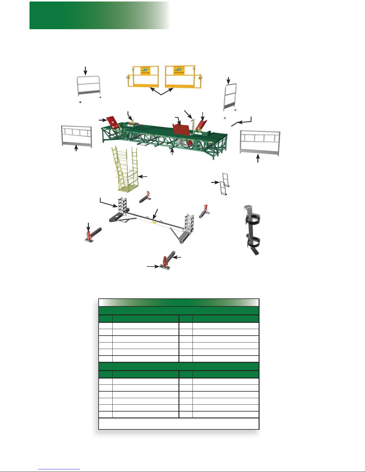
1 - MOTORIZED UNIT
Motorized Unit Overview
Sliding door guardrails
84" (213 cm)
door support
guardrail
84" (213 cm)
end guardrail
with pockets
72" (183 cm)
outrigger
Access
walkway
Plank-end
guardrails
Bottom mast
section (welded
on base)
Adjustable
jack
Mudsill
Base
Control post
24' (4,3 m) motorized
unit structure
Access panel
Hooks
Engine
access panel
List of components included with shipped unit
M2 SERIES 24' (7,3 m) MOTORIZED UNIT
Qty Component Qty Component
1
M2 Series 24' (7,3 m) motorized unit
1
1 1/2" wrench
1 15/16" wrench 2 84" (213 cm) end guardrails
2 sliding guardrail doors 4 pockets for 84" (213 cm) end guardrails
2 84" (213 cm) guardrail doors 6 72" (183 cm) outriggers
2 plank-end guardrails 1 Owner’s manual
1
support for fi re extinguisher
M2 SERIES 14' (4,3 m) MOTORIZED UNIT
Qty Component Qty Component
1
M2 Series 14' (4,3 m) motorized unit
1
1 1/2" wrench
1 15/16" wrench 2 84" (213 cm) end guardrails
2 sliding guardrail doors 4 pockets for 84" (213 cm) end guardrails
2 44" (112 cm) guardrail doors 4 72" (183 cm) outriggers
2 plank-end guardrails 1 Owner’s manual
1
support for fi re extinguisher
Note
The list of components included with each shipped motorized unit may change without notice.
24' (7,3 m) motorized unit
Mast tie
door
Note: Items depicted in illustrations may differ from actual products.
Support for fi re
extinguisher
Base
outrigger
84" (213 cm)
end guardrail
with pockets
84" (213 cm)
door support
guardrail
9
fi g. 1.4
fi g. 1.5
fi g. 1.6 fi g. 1.7
fi g. 1.8
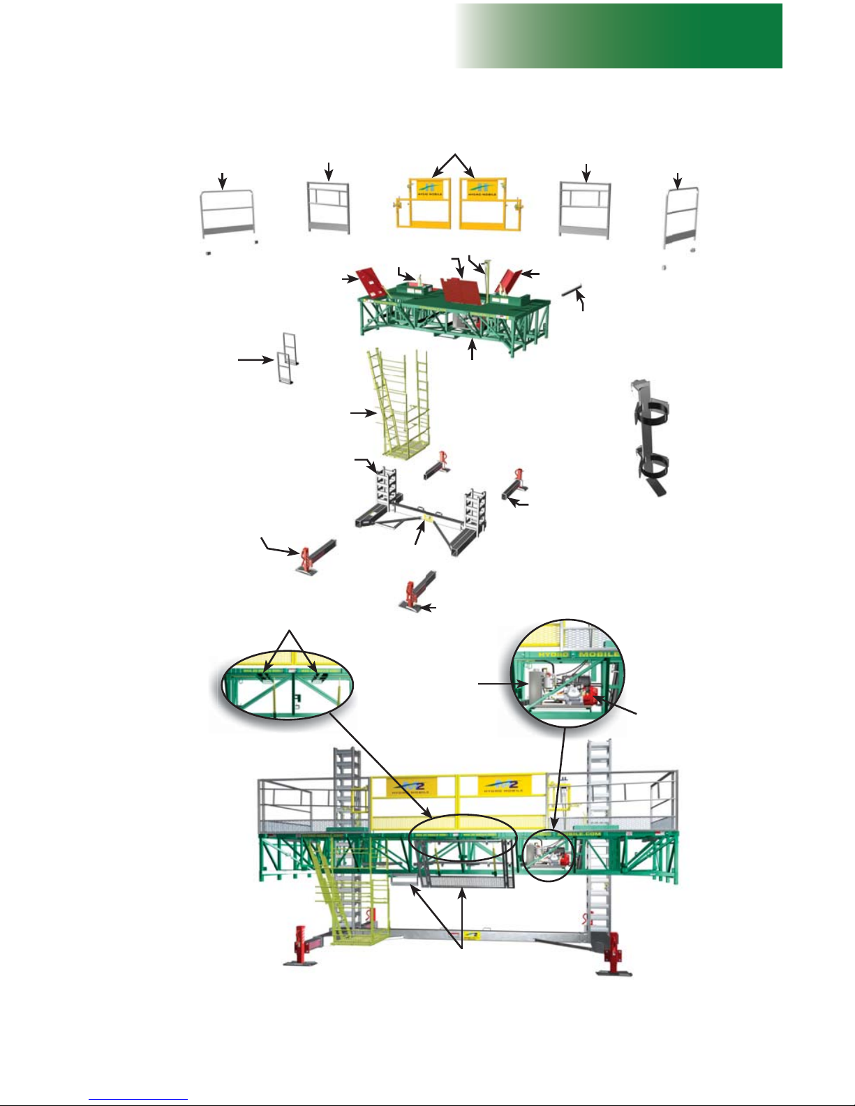
1 - MOTORIZED UNIT
Motorized Unit Overview
Sliding guardrail
doors
44" (112 cm) door
support guardrail
44" (112 cm) door
support guardrail
72" (183 cm)
outrigger
Adjustable
jack
Mudsill
Base
Control
post
14' (4,3 m) motorized
unit structure
Access
panel
Plank-end
guardrails
Access
walkway
Engine
access
panel
Hooks
14' (4,3 m) motorized unit
Guardrail storage
location
Forklift tubes
(for transport)
Hydraulic tank
Engine
Power pack
Mast tie
door
24' (7,3 m) motorized unit shown in this illustration
Bottom mast
section (welded on
base)
Support for fi re
extinguisher
Base
outrigger
84" (213 cm)
end guardrail
with pockets
84" (213 cm)
end guardrail
with pockets

10
fi g. 1.9
fi g. 1.10
1 - MOTORIZED UNIT
Motorized Unit Specifi cations
General Specifi cations
24' (7,3 m) model 14' (4,3 m) model
Dimensions of the
motorized unit (as
shipped)
84" x 288" x 48"
(2,1 m x 7,3 m x 1,2 m)
84" x 168" x 48"
(2,1 m x 4,3 m x 1,2 m)
Drive system Hydraulic ratchet drive Hydraulic ratchet drive
Maximum height 250' (76 m) 250' (76 m)
Distance between tie
levels
Up to 30' (9,14 m) if mast ties are
pre-installed
(refer to Masts and Mast Ties section for
complete information)
Up to 30' (9,14 m) if mast ties are
pre-installed
(refer to Masts and Mast Ties section for
complete information)
Freestanding height
35' (10,1 m) with extended telescopic base
outriggers
25' (7,6 m) with extended telescopic base
outriggers
Safety devices Safety hooks
Speed-activated
hook system
Safety hooks
Speed-activated
hook system
Specifi c Features
24' (7,3 m) model 14' (4,3 m) model
Platform
weight
(as shipped)
Total 7300 lb (3311 kg) 6000 lb (2722 kg)
Base 2300 lb (1043 kg) 1500 lb (680 kg)
MU structure
assembly
5000 lb (2268 kg) 4500 lb (2041 kg)
Maximum
load capacity
Single unit
installation
16,600 lb at 64'
(7530 kg at 19,7 m)
19,300 lb at 34'
(8754 kg at 10,4 m)
Multiple units
installation
30,000 lb at 148'
(13 607 kg at 45,1 m)
32,800 lb at 108'
(14 878 kg at 32,9 m)
Maximum lifting capacity 22,000 lb (9979 kg) 22,000 lb (9979 kg)
Vertical travel speed 3' (0,9 m) per minute 3' (0,9 m) per minute
Mast section
16" x 16" x 60"
(40,6 cm x 40,6 cm x 1,5 m)
235 lb (107 kg) per section
16" x 16" x 60"
(40,6 cm x 40,6 cm x 1,5 m)
235 lb (107 kg) per section
Bridges
Refer to the Bridges section for
dimensions
Refer to the Bridges section for
dimensions
Guardrails (included)
Sliding guardrail doors (2)
Plank-end guardrails (2)
84" (213 cm) end guardrails (2)
84" (213 cm) door support guardrails (2)
Sliding guardrail doors (2)
Plank-end guardrails (2)
84" (213 cm) end guardrails (2)
44" (112 cm) door support guardrails (2)

11
fi g. 1.11
fi g. 1.12
fi g. 1.13
1 - MOTORIZED UNIT
Motorized Unit Specifi cations
fi g
. 1.1
1
Hydraulic Specifi cations
Component Specifi cations
Double gear pump 2 x 3.18 GPM (2 x 12,02 l/min)
Hydraulic cylinder
2 x 3 1/2" x 23 1/2" x 1 1/2" (8,9 cm x 59,7 cm x 3,8 cm) with 3000 psi
counterbalance
Hydraulic tank capacity 5.26 US gal (19,9 l)
Hydraulic oil
Dexron III
ATF
Oil fi lter
Ikron fi lter model HE K44-20-135-AS-SP010
(HM part number A0410000-0004)
fi g
. 1
.12
Engine Specifi cations
24' (7,3 m) model 14' (4,3 m) model
Model Honda GX270 Honda GX270
Rated power 9 HP @ 3600 RPM 9 HP @ 3600 RPM
Consumption 313 g / kWh (230 g / hph) 313 g / kWh (230 g / hph)
Spark plug BPR6ES BPR6ES
Oil type SAE 10W30 SAE 10W30
Gasoline tank capacity 1.6 US gal (6 l) 1.6 US gal (6 l)
Oil capacity 1.16 US qt (1,10 l) 1.16 US qt (1,10 l)
Electrical power supply 12 VDC – 10 Ah 12 VDC – 10 Ah
Battery 12 VC – 230 CCA 12 VC – 230 CCA
For any other information regarding the use and maintenance of Honda engines, refer to the Honda User’s manual.
1
measured at 23' (7 m) @ 3600 RPM
2
with super silent muffl er, noise level is 76 dB(A)
1
measured at 23'
(7
m) @
3600
R
PM
Operation Specifi cations
Wind exposure
Maximum wind speed allowed
During operation (of a setup with mast ties) 35 mph (56 km/h)
During erecting and dismantling (all types of setups),
for freestanding installations and setups equipped with
weather protection
28 mph (45 km/h)
When unit is not in use 94 mph (150 km/h)
A setup with mast ties should only be used on masts whose height does not exceed 250' (76 m).
For complete information about wind speed restrictions and recommendations, see warning on p. 7.
A freestanding setup should only be used on masts whose height does not exceed 35' (10,1 m) for 24' (7,3 m) motorized
units and 25' (7,6 m) for 14' (4,3 m) motorized units, with extended telescopic base outriggers for both motorized unit
models
Noise exposure
Standard noise level 1 = 83 dB(A)
2

12
fi g. 1.14
1 - MOTORIZED UNIT
Motorized Unit Specifi cations
Weight of Components
Description Weight
24' (7,3 m) motorized unit 7300 lb (3311 kg)
14' (4,3 m) motorized unit 6000 lb (2722 kg)
24' (7,3 m) base assembly 2300 lb (1043 kg)
14' (4,3 m) base assembly 1500 lb (680 kg)
24' (7,3 m) structure assembly 5000 lb (2268 kg)
14' (4,3 m) structure assembly 4500 lb (2041 kg)
Mast assembly 235 lb (107 kg)
Walkway operator assembly 420 lb (191 kg)
6' (1,8 m) bearing bridge adapter assembly 900 lb (408 kg)
10' (3 m) modular bridge assembly 1360 lb (617 kg)
5' (1,5 m) modular bridge assembly 795 lb (361 kg)
Multi-purpose insert bridge assembly 800 lb (363 kg)
72" (183 cm) outrigger kit 25 lb (11 kg)
120" (305 cm) outrigger kit 55 lb (25 kg)
Sliding guardrail door - LEFT assembly for 24' (7,3 m) motorized unit 68 lb (31 kg)
Sliding guardrail door - RIGHT assembly for 24' (7,3 m) motorized unit 68 lb (31 kg)
Sliding guardrail door - LEFT assembly for 14' (4,3 m) motorized unit 50 lb (23 kg)
Sliding guardrail door - RIGHT assembly for 14' (4,3 m) motorized unit 50 lb (23 kg)
84" (213 cm) door support guardrail for 24' (7,3 m) motorized unit 70 lb (32 kg)
44" (112 cm) door support guardrail for 14' (4,3 m) motorized unit 50 lb (23 kg)
84" (213 cm) end guardrail 60 lb (27 kg)
60" (150 cm) guardrail 32 lb(15 kg)
Plank-end guardrail 30 lb (14 kg)
Movable guardrail assembly – TYPE 2 75 lb (34 kg)
Hoist main assembly 1860 lb (844 kg)
Hoist power pack rack assembly 750 lb (340 kg)
Hoist power pack bracket adapter for 14' (4,3 m) motorized unit 30 lb (15 kg)
Monorail beam assembly 85 lb (39 kg)
Junction plate assembly 19,5 lb (9,5 kg)
Monorail beam attachment assembly 27 lb (12 kg)
Weather protection – complete kit 224 lb (102 kg)
Weather protection connection tube kit 68 lb (31 kg)
Weather protection post assembly – TYPE 1 37 lb (17 kg)
Weather protection top outrigger kit 74 lb (34 kg)
Swivel bridge assembly (with guardrail) 800 lb (363 kg))
5' (1,5 m) square bridge assembly 390 lb (177 kg)
Flush bearing bridge adapter 350 lb (159 kg)
Wheel set 535 lb(243 kg)
Square bridge adapter assembly 230 lb (112 kg)
13
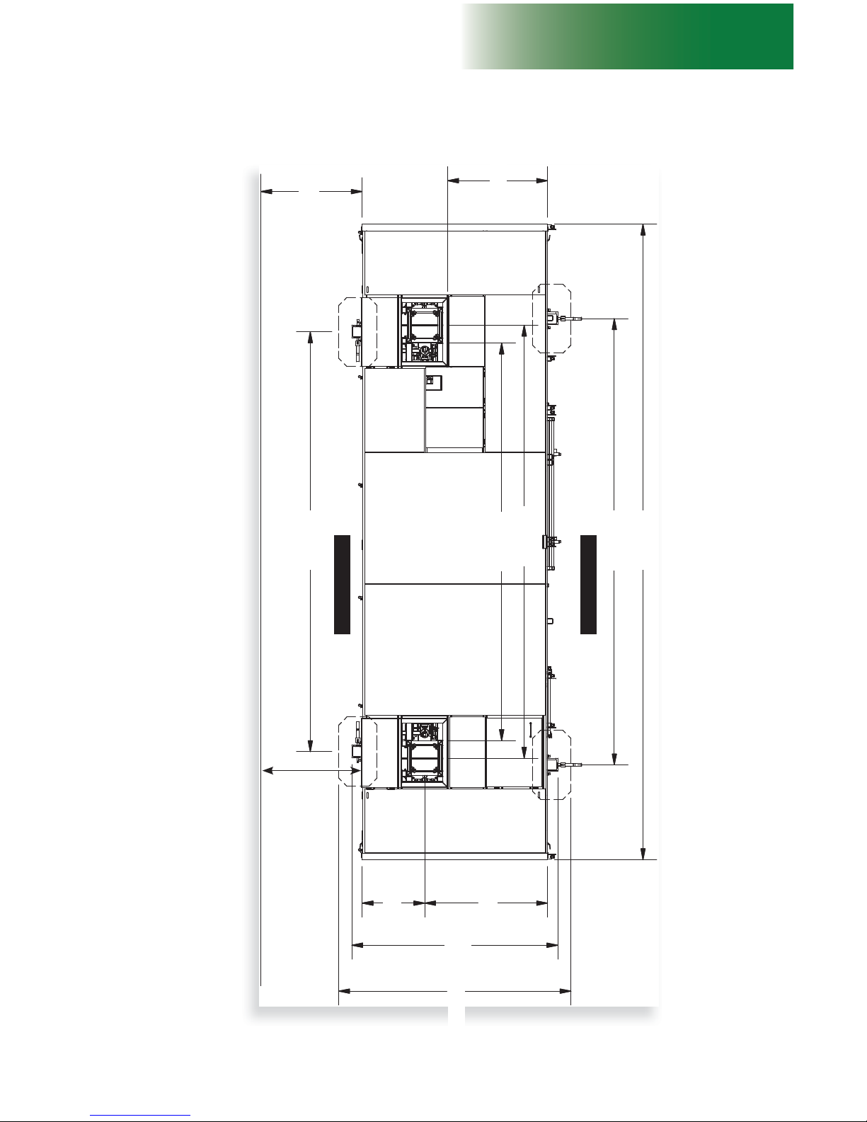
fi g. 1.15
1 - MOTORIZED UNIT
Motorized Unit Specifi cations
Front
Back
Dimensions of the Motorized Unit
190 3/16"
483,1 cm
28 3/8"
72,1 cm
105 1/4"
267,3 cm
55 5/8"
141,3 cm
180 1/8"
457,5 cm
196 3/16"
498,3 cm
202 3/16"
513,6 cm
288"
731,5 cm
45 1/4"
114,9 cm
A
* 141 3/8" (359,1 cm) with outriggers fully extended
24' (7,3 m) motorized unit
93 3/8"
237,2 cm
*
A = Distance from fi nished wall. For more information,
refer to the general installation guidelines, on p. 18.
There must be an 11" (28 cm) clearance between
the front edge of the motorized unit deck and the
fi nished wall
14
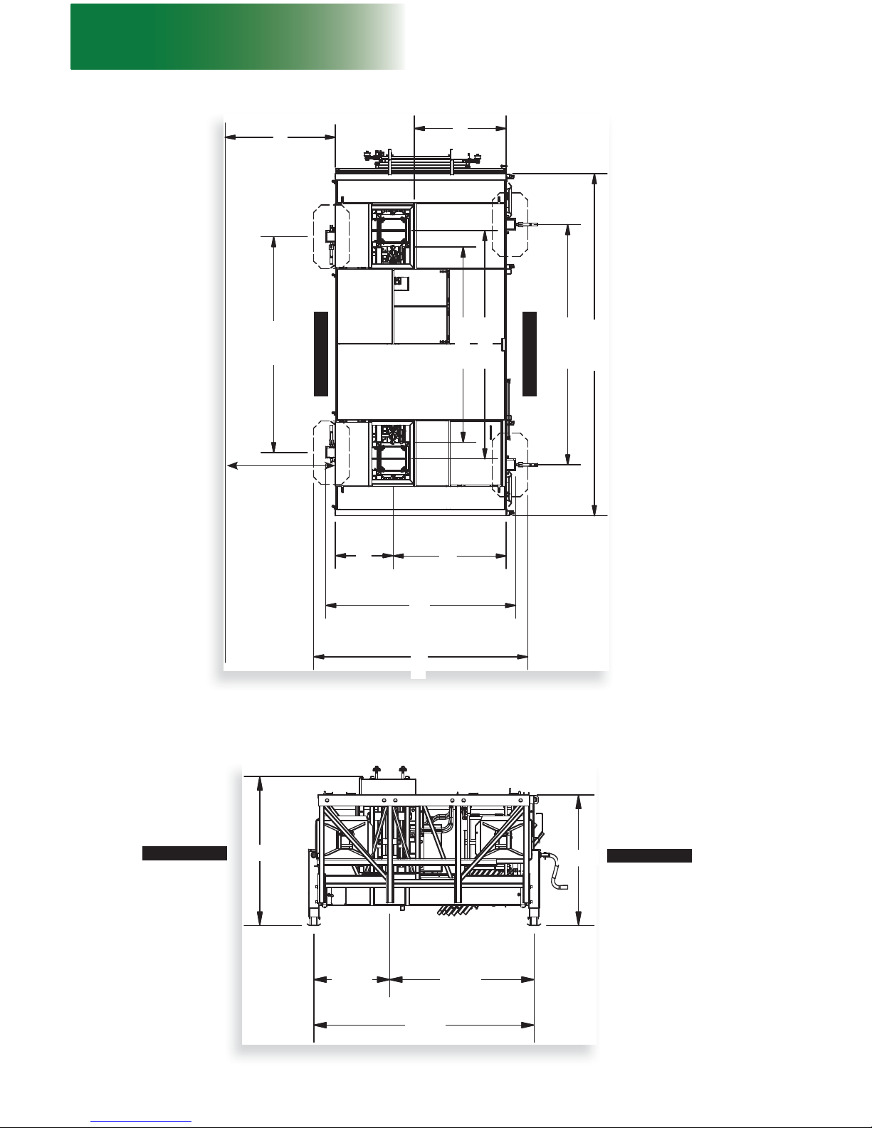
fi g. 1.16
fi g. 1.17
1 - MOTORIZED UNIT
14' (4,3 m) motorized unit
Dimensions of the Motorized Unit
106 3/16"
271,5 cm
28 3/8"
72,1 cm
Front
Back
105 1/4"
267,3 cm
93 3/8"
237,2 cm
55 5/8"
141,3 cm
96 1/8"
244,2 cm
112 1/4"
285,1 cm
118 3/16"
300,2 cm
168 1/4"
427,4 cm
* 141 3/8" (359,1 cm) with outriggers fully extended
45 1/4"
114,9 cm
A
*
Side view dimensions
24' (7,3 m) motorized unit and 14' (4,3 m) motorized unit
54 1/4"
137,8 cm
Front
Back
47 1/2"
120,7 cm
30 5/16"
77 cm
57 9/16"
146,2 cm
87 7/8"
223,2 cm
There must be an 11” (28 cm)
clearance between the front edge
of the motorized unit deck and the
fi nished wall
A = Distance from fi nished wall. For more information,
refer to the general installation guidelines, on p. 18.
15
fi g. 1.18
fi g. 1.19
1 - MOTORIZED UNIT
Positioning the Motorized Unit
Mudsill
Jack
Cribbing may be
required to distribute
reaction depending
on the bearing
surface
WARNING
Make sure the ground or support surface capacity meets with values
included in the Minimum Bearing Surface Capacities table (fi g. 1.18). Soil
compacting, cribbing or shoring can increase bearing capacity. Contact an
engineer for assistance.
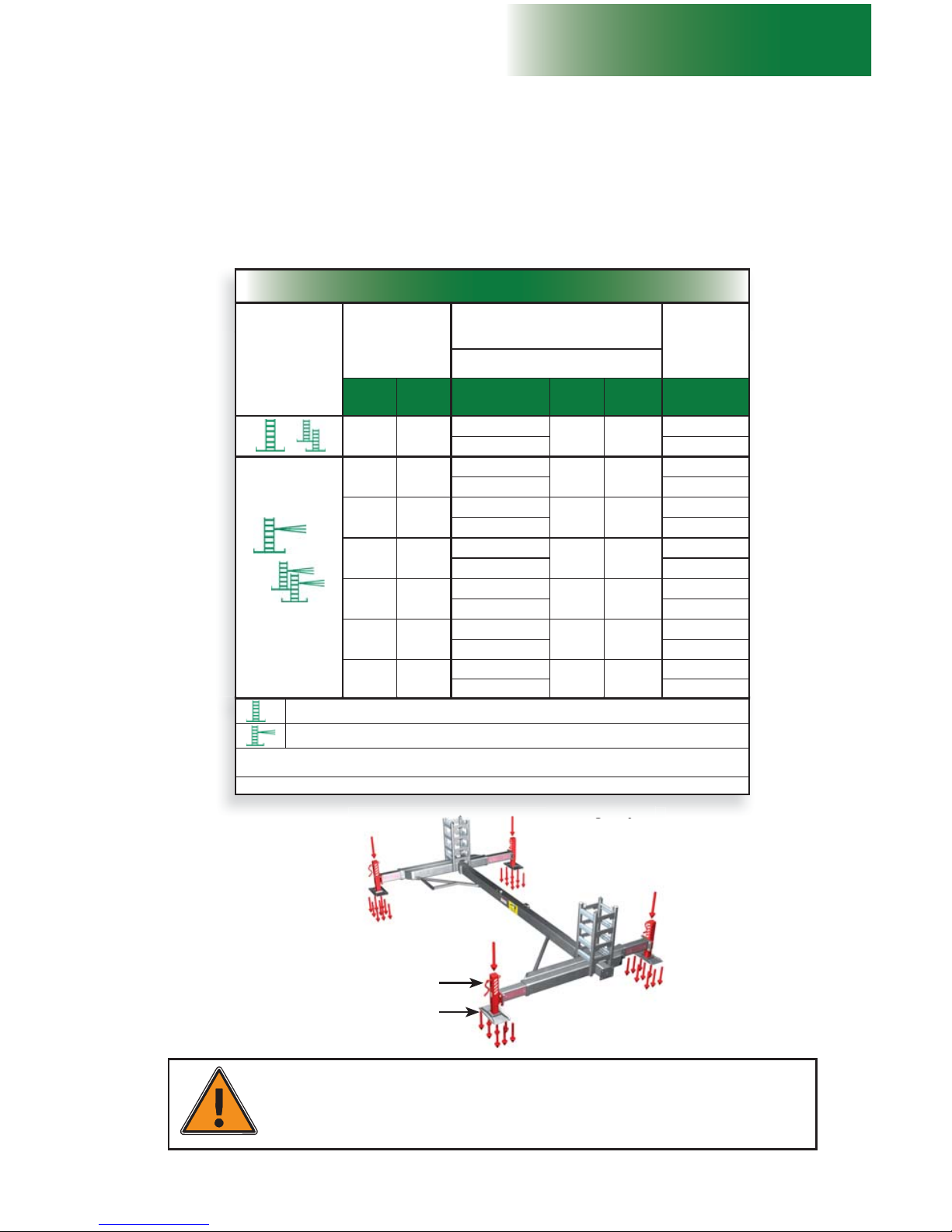
Minimum Bearing Surface Capacities
Height
Motorized unit
(pressure per mudsill)
Load under
mast
Mudsill: 14" x 28" (35,6 x 71 cm)
Contact surface: 392 sq in (,25 m2)
(ft) (m) Load reaction
Load
pressure
(psi)
Load
pressure
(kpa)
Load reaction
35 10,7
15 972 lb
41 283
21 880 lb
7245 kg
9925 kg
50 15,2
15 005 lb
38 262
22 735 lb
6806 kg
10 312 kg
75 22,9
15 830 lb
40 276
23 985 lb
7180 kg
10 879 kg
100 30,5
16 655 lb
43 296
25 235 lb
7556 kg
11 446 kg
150 45,7
18 305 lb
47 324
27 735 lb
8303 kg
12 580 kg
200 61,0
19 955 lb
51 352
30 235 lb
9051 kg
13 714 kg
250 76,2
21 605 lb
55 379
32 735 lb
9800 kg
14 848 kg
Bearing surface
Before installing the motorized unit, make sure the bearing surface under it is level, clear of
debris and has the proper bearing capacity. When required, appropriate cribbing must be
placed under the mudsills on the base to distribute the load. It is important to make sure that
the bearing surface is stable and has not been subject to any type of erosion or deterioration
caused by weather conditions (snow, rain, etc.).
General Concept
Cribbi
ng
may
be
Freestanding installation
Tied installation
Load reactions under each mast must be considered for an installation using mast base plates. For
more information about mast base plates, refer to p. 115 of the Accessories section.
Load reactions in above table include a dynamic factor.
16
WARNING / AVERTISSEMENT / AVISO
A0800100-0011
Make sure that
support surface
under jacks
has sufficient
bearing capacity.
Veiller à ce que
la capacité de
charge de la
surface d’appui
sous les vérins
soit adéquate.
Asegúrese que la
capacidad de carga
de la superficie de
apoyo bajo los
gatos sea la
adecuada.
fi g. 1.20
fi g. 1.21
fi g. 1.22
fi g. 1.23
1
2
1
2
2
1 - MOTORIZED UNIT
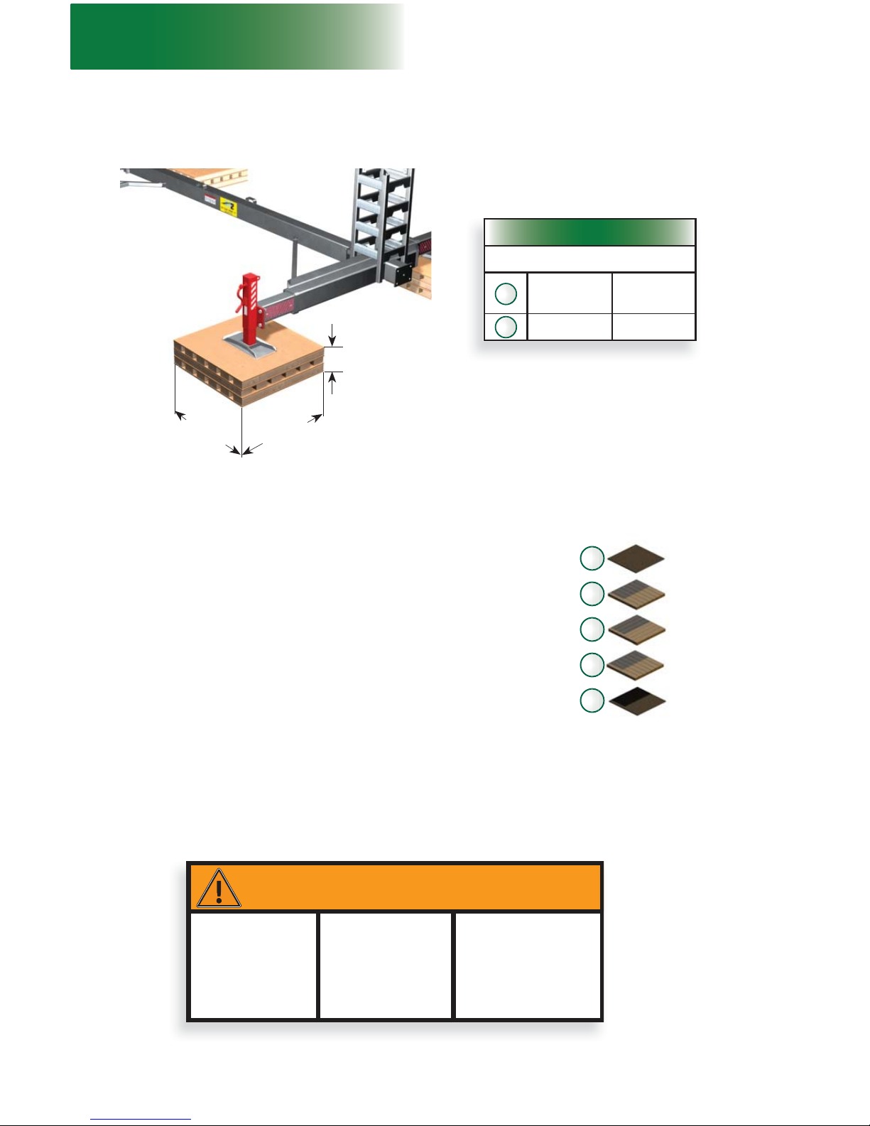
Suggested Cribbing
40" x 40" x 6"
(102 cm x 102 cm x
15,2 cm)
Plywood
40" x 40" x 3/4"
(102 cm x 102 cm x 1,9 cm)
2
2"x 10" x 40"
(5 cm x 25 cm x 102 cm)
12
Suggested cribbing for most bearing surfaces
The plywood and lumber used as cribbing should be secured together to prevent slipping.
Using screws instead of nails for securing will prolong the service life of lumber and plywood
used as cribbing.
Positioning the Motorized Unit
40" (102 cm)
40" (102 cm)
6" (15,2 cm)
Values shown in the above table
are for reference only. Any cribbing
equivalent to or larger than these
values can be used.
The type of cribbing chosen may vary according
to the bearing surface where the setup must be
installed.
For example, a setup installed on a concrete slab that
is covering the bearing surface would require cribbing
consisting of only one plywood panel under each mudsill
while a setup installed on a concrete slab that is covering
an indoor garage would require shoring in addition to
plywood cribbing.
A setup installed on a bearing surface composed of
gravel, sand or any such type of surface would require
stronger cribbing under the mudsills.
In cases where shoring is required, it is recommended
to contact an engineer for assistance.
Plywood
3/4" (1,9 cm)
Lumber
1 1/2" (3,8 cm)
Plywood
3/4” (1,9 cm)
Lumber
1 1/2" (3,8 cm)
Lumber
1 1/2" (3,8 cm)
1
2
17
fi g. 1.24
1 - MOTORIZED UNIT
Setups with M2 Series motorized units and bridges can be freestanding or tied, depending on the
equipment and accessories required and used in the confi guration. A standard confi guration is
an installation that does not require the use of additional equipment, such as a forward extension
bridge, a swivel bridge or a planking confi guration wider than four planks, or the use of accessories
such as weather protection, a hoist or a monorail.
It is important to note that non standard confi gurations are not allowed for freestanding M2 Series
installations. It is mandatory to refer to the Mast Tie Schedule table on p. 70 of the Masts and
Mast Ties section before the installation of any M2 Series confi guration, whether freestanding or tied.
The installation of an M2 Series setup with mast ties (standard or non standard confi guration) can
be achieved using a progressive installation method or through complete pre-installation of tie
levels. The confi guration required by the layout plan and the schedule of installation of tie levels
will determine which method of installation is more appropriate.
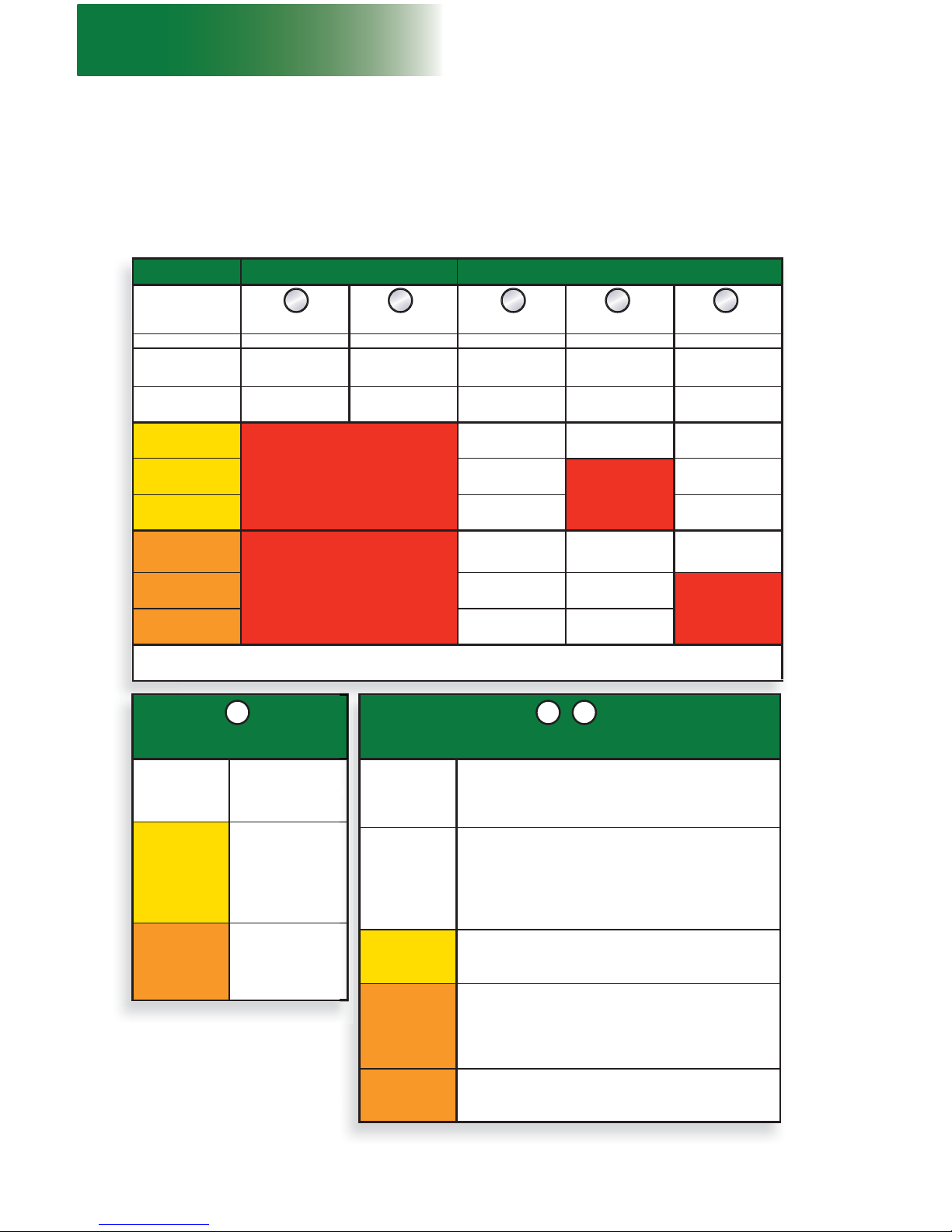
It is also important to consider that for tied installations, the combined use of equipment and
accessories required to achieve an non standard confi guration may not be allowed on a same
installation. Refer to the Combination of Standard and Non Standard Confi gurations table in fi g. 1.24
for more information on the combinations allowed.
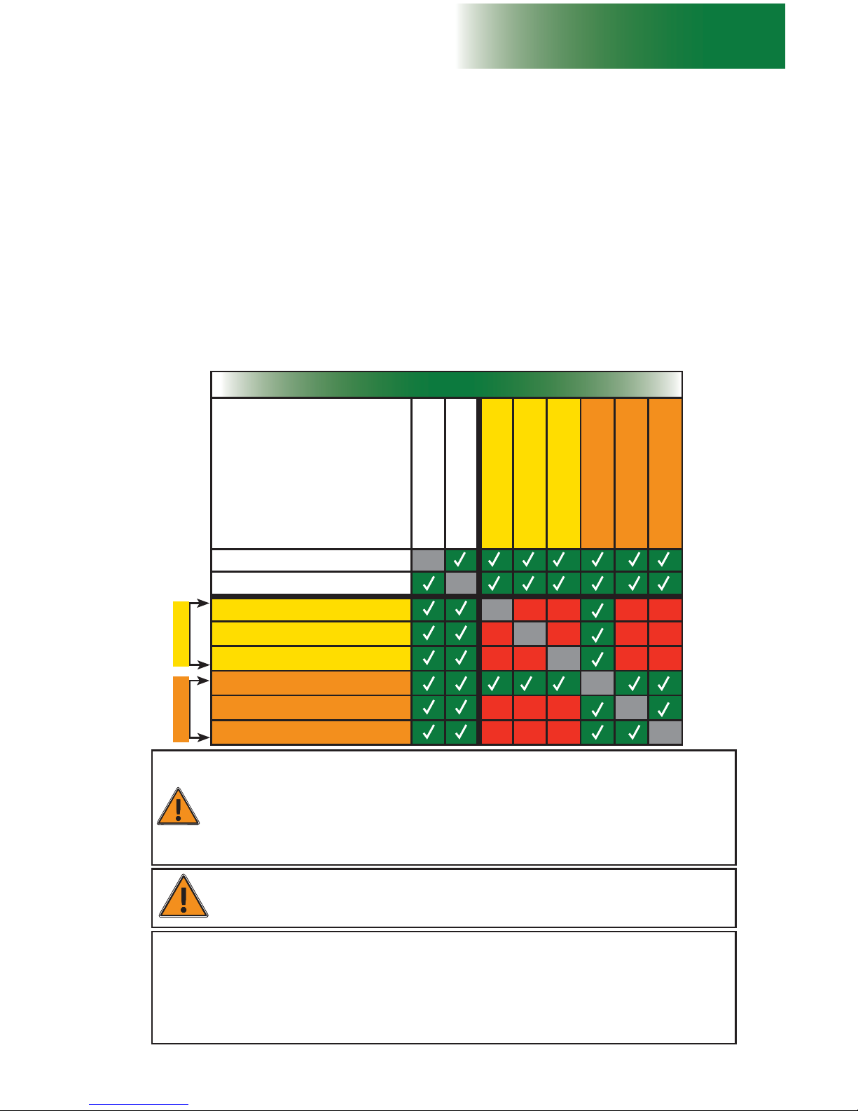
Combination of Standard and Non Standard Confi gurations
Confi gurations
Standard – Cantilever
Standard – Bearing bridge
5 to 8 planks
Forward extension (
MPI)
Swivel bridge
Hoist and support structure
Weather protection
Monorail
Standard – Cantilever
Standard – Bearing bridge
5 to 8 planks
Forward extension (
MPI)
Swivel bridge
Hoist and support structure
Weather protection
Monorail
WARNING
It is important to note that non standard confi gurations are not allowed for a
freestanding installation.
Defi nition of a standard confi guration
A standard confi guration, referred to throughout this owner’s manual and related documentation,
is an installation that does not require the use of additional equipment, such as a forward extension
bridge, a swivel bridge or a planking confi guration wider than four planks nor the use of accessories
such as weather protection, a hoist or a monorail.
It is mandatory to refer to the Load Capacities section on p. 80 for the number of bridges allowed
in a standard single unit or multiple units installation.
Setup and confi gurations
General Guidelines
EquipmentAccessories
WARNING
Failure to select and follow the mast tie installation schedule appropriate for the confi guration
could adversely affect worker safety, leading to serious injury or death and equipment damage.
It is mandatory to refer to the Mast Tie Schedule table on p. 70 of the Masts and Mast Ties
section before the installation of any M2 Series confi guration. It is also mandatory to refer
to the Load Capacities section on p. 80 for more information about the loads allowed in a
confi guration. It is also recommended to review and follow the instructions included in this manual
for the installation and use of each accessory and equipment to be installed.

18
1 - MOTORIZED UNIT
1- Installation should be carried out by qualified erectors/dismantlers under the
supervision of a competent person, in accordance with all applicable local regulations.
2- In reference to the plan/layout drawing, make sure that all the components required
are available. Establish the position of the motorized unit, determine if there are
obstacles and what are the cribbing and mast tie requirements.
3- Before installing the motorized unit, determine where the cribbing and the mudsills
will rest. The bearing surface under the motorized unit should be level, clear of debris
and have the proper bearing capacity (see the Minimum Bearing Surface Capacities
table, fi g. 1.18, p. 15). Should the actual bearing capacity be inferior to the values in
the table, please seek instructions and recommendations from Hydro Mobile.
4- On freestanding installations, the base outriggers on the back of the unit must be
extended completely to a total of 24" (61 cm) and locked in place with a lock pin
(second hole).
The base outriggers on the front of the unit must be extended and locked in place to
the appropriate distance according to the number of planks required and allowed for
the installation, as shown in fi g. 1.25, p. 19.
With the front base outriggers completely extended, the maximum width of planking
allowed in front of the unit on a freestanding installation is a three-plank wide
confi guration.
5- On tied installations, the base outriggers must be closed completely . The maximum
width of planking allowed in front of the unit is an eight-plank wide confi guration and
requires the use of optional outriggers and accessories. Refer to p. 95 of the
Accessories section for more information about outriggers and planking confi gurations.
For more information about planking and mast ties, refer to the Mast Tie Schedule
table on p. 70 of the Masts and Mast Ties section.
6- Distance from the fi nished wall (see “A” in fi g. 1.15, p. 13 and fi g. 1.16, p. 14)
should be the number of planks multiplied by the width of one plank, while allowing
6" to 8" (15 cm to 20 cm) of play. Add an additional 2" (5 cm) if using a toe board.
Refer to applicable local regulations to determine play or the maximum allowable
distance between the motorized unit, including its accessories, and the face of the work.
7- Mark the position of mudsills while taking center-to-center distances into account.
Base level differences can be compensated by adjusting the height of the base
jacks or by building wood cribbing. Major differences in the level of the bearing surface
or obstacles can be bypassed using mast base plates. Refer to p. 115 of the
Accessories section for instructions on the installation and use of mast base plates.
8- Make sure that all loads have been removed from the platform and that all workers
have stepped down before lifting and transporting the motorized unit. Refer to p. 37
for more information on the lifting and moving of a motorized unit. Unload the motorized
unit with a rough terrain forklift or a crane. When moving the motorized unit with a
forklift, the unit must be lifted by the designated areas on the platform (see fi g. 1.6,
p. 9).
9- Using a rough terrain forklift, a crane or an optional wheel set, position and align the
motorized unit with the face of the work or the structure. Before lowering the unit on
the bearing surface, lower the base jacks by 4" to 5" (11 cm to 13 cm). Refer
to p. 102 of the Accessories section for more information about lifting and moving
a motorized unit or a setup with a wheel set.
10- Install a mast section on each of the bottom mast sections. Refer to p. 69 of the Masts
and Mast Ties section for instructions on how to install mast sections. V erify that each
mast is plumb on both its front and side axis. If required, level the motorized unit using
the adjustable jacks on the base. If mast sections remain out of plumb after adjusting
the base jacks, contact the Hydro Mobile technical support team.
11- Remove the mast locking bar from both bottom mast sections. Store the mast locking
bars in their storage location. For instructions on the removal and storage of mast
locking bars, refer to p. 62 of the Power Pack and Operating Components section.
12- Remove the transport hook from each cylinder. Retrieve and install the cylinder and
secondary hooks on each mast. Store the transport hooks in their storage location.
For instructions on the installation and use of hooks, refer to p. 62 of the Power
Pack and Operating Components section.
Setup and Confi gurations
General Guidelines
19
fi g. 1.25
fi g. 1.26
X
A
C
A
C
B
1 - MOTORIZED UNIT
Setup and confi gurations
General Guidelines
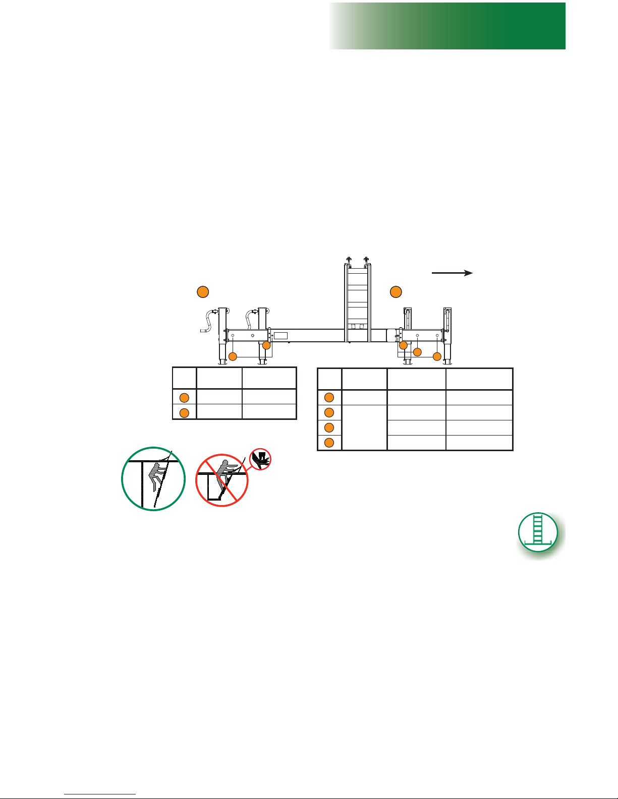
13- The platform can safely be accessed by the front of the mast when it is less than
10' (3 m) above base level. Once the platform has been raised over 10' (3 m) above base
level, use the access ladder on the walkway to reach the platform. Make sure that
the access ladder is completely extended. T o avoid any crushing hazard, the access
walkway must not be used if the access ladder is not entirely extended (as
shown in fi g. 1.26).
14- It is also suggested to install an optional retractable rest platform when the platform has
been raised at more than 30' (9 m) above base level or beyond the maximum allowable
height prescribed by local regulations for mast climbing without a rest platform. Refer to
p. 94 of the Accessories section for instructions on the installation and use of a
retractable rest platform.
15- Proceed to the following instruction steps for the installation of the setup, as the
confi guration requires.
Installation of a single unit confi guration – freestanding
The following installation steps can be used for standard confi gurations only. Non
standard confi gurations are not allowed for freestanding installations. For more information
about the defi nition of a standard confi guration, refer to p. 17 of this section.
1- Prepare the motorized unit and the area where it will be installed as described in the
general guidelines on p. 18 (steps 1 through 15). Make sure that the base outriggers
on the back of the motorized unit are completely extended and the base outriggers
on the front of the unit are extended to the appropriate distance, as described in step
4 of the general guidelines and in fi g. 1.25. Make sure all base outriggers are properly
locked in place.
Positioning the motorized unit
Installation of bridges
2- With the motorized unit at base level, install as many bridges as is required and
allowed. For instructions on how to install a bridge, refer to p. 43 of the Bridges section.
Refer to the Load Capacities section on p. 80 for the maximum number of bridges
allowed in a setup.
To wall
Rear Front
Type of
installation
Length of base
outriggers
With mast ties 0" ( 0 cm)
Freestanding 24" (61 cm)
Type of
installation
Maximum
number of planks
Length of base
outriggers
With mast ties As allowed 0" ( 0 cm)
Freestanding
0 - 1 0” ( 0 cm)
2 11" (28 cm)
3 24" (61 cm)
C
A
A
C
A
B
B
Never used at the rear
A
Position for TIED installation
Positioning of base outriggers
To avoid any crushing hazard, the access walkway
must not be used if the access ladder is not entirely
extended

20
1 - MOTORIZED UNIT
Setup and Confi gurations
Installation of a single unit confi guration – freestanding
Installation of a multiple units confi guration – freestanding
(requires the use of two bearing bridge adapters – sold separately)
The following installation steps can be used only for a standard confi guration. Non
standard confi gurations are not allowed for freestanding installations. For more information
about the defi nition of a standard confi guration, refer to p. 17 of this section.
1- Prepare the fi rst motorized unit and the area where the setup will be installed as described
in the general guidelines on p. 18 (steps 1 through 15). Make sure that the base outriggers
on the back of the motorized unit are completely extended and the base outriggers
on the front of the unit are extended to the appropriate distance, as described in step
4 of the general guidelines and in fi g. 1.25, p. 19. Make sure all base outriggers
are properly locked in place.
Positioning the fi rst motorized unit
Verifi cation of the setup
4- Make a fi nal verifi cation of the setup before starting to install mast sections. Make
sure all the guardrails are in place and secure (see p. 91 of the Accessories section
for more information about guardrails). In all cases where workers are exposed to fall
hazards greater than specifi ed by local regulations, the installation of guardrails or
face guardrail supports is mandatory.
5- Before authorizing workers to use the motorized unit, perform every step in the daily
inspection checklist. If required, fi ll out the handover sheet to complete the installation.
Refer to p. 120 of the T ransport, Storage and Maintenance section for more information
about the daily inspection checklist and to p. 124 for information about the handover
sheet.
WARNING
A freestanding setup must not be raised over 35' (10,1 m) with a 24' (7,3 m)
motorized unit and 25' (7,6 m) with a 14' (4,3 m) motorized unit.
Positioning the second motorized unit
2- Determine the position of the second motorized unit while making sure that the ideal
distance is kept between the two motorized units. Refer to the installation instructions
for a bearing bridge structure, on p. 46 of the Bridges section.
3- Adjust the outriggers and install planks, as required and allowed (see p. 95 of the
Accessories section for more information).
Installation of outriggers and planking
Installation of mast sections
6- Using a crane or a rough terrain forklift, load mast sections on the unit. Mast
sections should be stored horizontally and distributed equally on the motorized
unit to ensure good balance. Refer to the Load Capacities section on p. 80 for
more information about loading the platform.
7- Proceed with the installation of mast sections. Refer to p. 69 of the Masts and Mast
Ties section for instructions on how to install mast sections.
8- Install as many mast sections as required to reach the desired height, equal or inferior
to the maximum allowable height for a freestanding installation, making sure throughout
the process that each mast remains plumb on both its front and side axis. It is important
to install mast sections alternately – one on mast, then one on the other, to ensure
good balance. Refer to p. 70 of the Masts and Mast Ties section for more details on
the maximum allowable height for a freestanding installation.
9- It is important to make sure to verify the mast bolts on each mast when lowering the
platform to make sure they are tightened to the proper torque and are in good
condition, especially on brand-new mast sections, as the galvanized coating
may have compressed. In all cases, mast bolts must be tightened to a torque of
120 lb-ft (163 N-m). Failure to tighten bolts properly may lead to serious injury or
death.

21
1 - MOTORIZED UNIT
Setup and confi gurations
Installation of a multiple units confi guration – freestanding
(requires the use of two bearing bridge adapters – sold separately)
Positioning the second motorized unit (cont’d)
3- Prepare the second motorized unit and the area where it will be installed as described
in the general guidelines on p. 18 (steps 1 through 15). Make sure that the base outriggers
on the back of the motorized unit are completely extended and the base outriggers
on the front of the unit are extended to the appropriate distance, as described in step
4 of the general guidelines and in fi g. 1.25, p. 19. Make sure all base outriggers
are properly locked in place.
Verifi cation of the setup
6- Make a fi nal verifi cation of the setup before starting to install mast sections. Make
sure all the guardrails are in place and secure (see p. 91 of the Accessories section
for more information about guardrails). In all cases where workers are exposed to fall
hazards greater than specifi ed by local regulations, the installation of guardrails or
face guardrail supports is mandatory.
7- Before authorizing workers to use the motorized units, perform every step in the daily
inspection checklist. If required, fi ll out the handover sheet to complete the installation.
Refer to p. 120 of the T ransport, Storage and Maintenance section for more information
about the daily inspection checklist and to p. 124 for information about the handover
sheet.
Installation of the bearing bridge structure and the cantilever bridges
4- Proceed with the installation of the bearing bridge structure and the cantilever bridges.
Refer to p. 46 of the Bridges section for more information on the installation of a
bearing bridge. It is mandatory to install any additional cantilever bridge after the
bearing bridge structure has been installed to avoid throwing the structure off balance.
5- Adjust the outriggers and install planks, as required and allowed (see p. 95 of the
Accessories section for more information).
Installation of outriggers and planking
WARNING
On freestanding installations, with the front base outriggers completely
extended, the maximum width of planking allowed in front of the unit is a
three-plank wide confi guration.
Installation of mast sections
8- Using a crane or a rough terrain forklift, load mast sections on the units. Mast
sections should be stored horizontally and distributed equally on each motorized
unit to ensure good balance. Refer to the Load Capacities section on p. 80 for
more information about loading the units.
9- Proceed with the installation of mast sections. Refer to p. 69 of the Masts and Mast
Ties section for instructions on how to install mast sections.
10- Install as many mast sections as required on each motorized unit until the setup
has reached the desired height, equal or inferior to the maximum allowable height for
a freestanding installation, making sure throughout the process that each mast remains
plumb on both its front and side axis. It is important to install mast sections alternately
– on the fi rst motorized unit, then on the second, to ensure good balance. Refer to
p. 21 of the Masts and Mast Ties section for more details on the maximum allowable
height for a freestanding installation.
11- It is important to make sure to verify the mast bolts on each mast when lowering the
platform to make sure they are tightened to the proper torque and are in good
condition, especially on brand-new mast sections, as the galvanized coating
may have compressed. In all cases, mast bolts must be tightened to a torque of
120 lb-ft (163 N-m). Failure to tighten bolts properly may lead to serious injury or
death.
22
fi g. 1.27
fi g. 1.28
fi g. 1.29
1 - MOTORIZED UNIT
Setup and Confi gurations
STANDARD CONFIGURATION NON STANDARD CONFIGURATION
Method of
installation of
tie levels
Progressive Pre-installation Progressive Pre-installation Pre-installation
Tie levels every 20' (6,1 m) 30' (9,1 m) 10' (3 m) 20' (6,1 m) 20' (6,1 m)
Standard
cantilever
bridges
Installed and
used
Installed but not
used
Installed and
used
Installed but not
used
Not installed
Standard
bearing bridges
Installed and
used
Installed but not
used
Installed and
used
Installed but not
used
Installed but not
used
5 to 8 planks
Installed and
used
Not installed Not installed
Forward
extension (
MPI)
Installed and
used
Not installed
Swivel bridge
Installed and
used
Not installed
Hoist
Installed and
used
Installed but not
used above last
tie level
Installed but not
used above last
tie level
Weather
protection
Installed and
used
Installed but not
used *
Monorail
Installed and
used
Installed but not
used *
* Installed but not used: accessory is installed but can only be used when tie levels have been completely installed
to top of work. Weather protection tarps must be installed only when tie level installation is complete.
The installation of an M2 Series setup with mast ties (standard or non standard confi guration)
can be achieved using a progressive installation method or through complete pre-
installation of tie levels. The confi guration required by the layout plan and the schedule
of installation of tie levels will determine which method of installation is more appropriate.
Use the tables in fi g. 1.27, fi g. 1.28, fi g. 1.29 and the Mast Tie Schedule table on p. 70 of
the Masts and Mast Ties section to guide the selection of the proper method of installation.
PROGRESSIVE INSTALLATION OF
TIE LEVELS
Standard
bridges
installed and
used
Standard bridges
can be installed and
used for workers and
material
Equipment
installed and
used
5 to 8 plank
confi guration,
forward extension
bridge and swivel
bridge can be
installed and used
for workers and
material
Accessories
installed and
used
Hoist, monorail and
weather protection
can be installed and
used
COMPLETE PRE-INSTALLATION OF TIE LEVELS TO THE TOP OF THE
WORK
Standard
bridges
installed but
not used
Any required and allowed standard bridges (cantilever or
bearing) can be installed but cannot be used for material
or workers until tie levels are complete to the top of the
work. For example, mast sections can be loaded on the
motorized unit only, not on bridges.
Standard
cantilever
bridges
must not be
installed;
bearing bridge
can be installed
but not used
Any required and allowed standard cantilever bridge must
not be installed until tie levels are complete to the top of
the work.
Any required and allowed standard bearing bridge can be
installed but not used until tie levels are complete to the top
of the work.
Equipment can
be installed but
not used
Any required and allowed additional equipment – 5 to 8
plank confi guration, forward extension bridge and swivel
bridge – can be installed but cannot be used until tie levels
are complete to the top of the work.
Accessories
installed but
not used
Any required and allowed accessory – monorail and
weather protection (structure only) – can be installed but
cannot be used until tie levels are complete to the top of
the work.
Weather protection tarps must be installed only when
tie level installation is complete.
Hoist installed
but not used
above last tie
level
If required and allowed, the hoist can be installed and used
to load mast sections only but cannot be used above the
last tie level installed.
Installation of confi gurations with mast ties
A B CA B
A B C

23
1 - MOTORIZED UNIT
Setup and confi gurations
Single unit confi guration with mast ties – progressive installation
The following installation steps can be used for both standard and non-standard
confi gurations with mast ties. For more information about the defi nition of a
standard confi guration, refer to p. 17 of this section.
A
1- Prepare the motorized unit and the area where the setup will be installed as described
in the general guidelines on p. 18 (steps 1 through 15). Make sure that all base
outriggers are completely closed.
Positioning the motorized unit
Installation of bridges, accessories and additional equipment
2- With the motorized unit at base level, install as many bridges as is required and
allowed. For instructions on how to install a bridge, refer to p. 43 of the Bridges section.
Refer to the Load Capacities section on p. 80 for the maximum number of bridges
allowed in a setup.
3- Install accessories and additional equipment as is required and allowed. For information
about the combined use of equipment and accessories allowed for a confi guration,
refer to the Combination of Standard and Non Standard Confi gurations table in
fi g. 1.24, p. 17. For instructions on the installation and use of forward extension or
swivel bridges, refer to the Bridges section on p. 43. For instructions on the
installation and use of a 5 to 8 plank confi guration, a hoist, a monorail or weather
protection, refer to the Accessories section on p. 91.
Verifi cation of the setup
5- Make a fi nal verifi cation of the setup before starting to install mast sections. Make
sure all the guardrails are in place and secure (see p. 91 of the Accessories section
for more information about guardrails). In all cases where workers are exposed to fall
hazards greater than specifi ed by local regulations, the installation of guardrails or
face guardrail supports is mandatory.
6- Before authorizing workers to use the motorized unit, perform every step in the daily
inspection checklist. If required, fi ll out the handover sheet to complete the installation.
Refer to p. 120 of the T ransport, Storage and Maintenance section for more information
about the daily inspection checklist and to p. 124 for information about the handover
sheet.
4- Adjust the outriggers and install planks, as required and allowed (see p. 95 of the
Accessories section for more information).
Installation of outriggers and planking
Installation of mast sections and mast ties
7- Using a crane or a rough terrain forklift, load mast sections on the unit. Mast
sections should be stored horizontally and distributed equally on the motorized
unit to ensure good balance. Refer to the Load Capacities section on p. 80 for
more information about loading the platform.
8- Install mast sections until a fi rst tie level is required. Refer to p. 69 of the Mast and
Mast Ties section for instructions on how to install mast sections. It is important to
install mast sections alternately – one on one mast, then one on the other, to ensure good
balance. For more information about the schedule of installation of tie levels, refer to
the Mast Tie Schedule table on p. 70 of the Masts and Mast Ties section. Refer to
p. 70 of the Masts and Mast Ties section for instructions on how to install mast ties.
9- Install as many mast sections as the plan layout requires and as is allowed. A setup
with mast ties should not be raised above 250' (76 m). Make sure throughout the
process that each mast remains plumb on both its front and side axis and that tie levels
are installed when required.
10- It is important to make sure to verify the mast bolts on each mast when lowering the
platform to make sure they are tightened to the proper torque and are in good
condition, especially on brand
-new mast sections, as the galvanized coating
may have compressed. In all cases, mast bolts must be tightened to a torque of
120 lb-ft (163 N-m). Failure to tighten bolts properly may lead to serious injury or
death.

24
1 - MOTORIZED UNIT
Setup and confi gurations
Multiple units confi guration with mast ties – progressive installation
(requires the use of two bearing bridge adapters – sold separately)
Positioning the fi rst motorized unit
1- Prepare the fi rst motorized unit and the area where the setup will be installed as
described in the general guidelines on p. 18 (steps 1 through 15). Make sure that all base
outriggers are completely closed.
Positioning the second motorized unit
2- Determine the position of the second motorized unit while making sure that the ideal
distance is kept between the two motorized units. Refer to the installation instructions
for a bearing bridge structure, on p. 46 of the Bridges section.
3- Prepare the second motorized unit and the area where it will be installed as described
in the general guidelines on p. 18 (steps 1 through 15).
Installation of the bearing bridge structure and the cantilever bridges
4- Proceed with the installation of the bearing bridge structure and the cantilever bridges.
Refer to p. 46 of the Bridges section for more information on the installation of a
bearing bridge. It is mandatory to install any additional cantilever bridge after the
bearing bridge structure has been installed to avoid throwing the structure off balance.
Installation of accessories and additional equipment
5- Install accessories and additional equipment as is required and allowed. For information
about the combined use of equipment and accessories allowed for a confi guration,
refer to the Combination of Standard and Non Standard Confi gurations table in
fi g. 1.24, p. 17. For instructions on the installation and use of forward extension or
swivel bridges, refer to the Bridges section on p. 43. For instructions on the
installation and use of a 5 to 8 plank confi guration, a hoist, a monorail or weather
protection, refer to the Accessories section on p. 91.
The following installation steps can be used for both standard and non-standard
confi gurations with mast ties. For more information about the defi nition of a
standard confi guration, refer to p. 17 of this section.
A
Verifi cation of the setup
7- Make a fi nal verifi cation of the setup before starting to install mast sections. Make
sure all the guardrails are in place and secure (see p. 91 of the Accessories section
for more information about guardrails). In all cases where workers are exposed to fall
hazards greater than specifi ed by local regulations, the installation of guardrails or
face guardrail supports is mandatory.
8- Before authorizing workers to use the motorized units, perform every step in the daily
inspection checklist. If required, fi ll out the handover sheet to complete the installation.
Refer to p. 120 of the T ransport, Storage and Maintenance section for more information
about the daily inspection checklist and to p. 124 for information about the handover
sheet.
9- Using a crane or a rough terrain forklift, load mast sections on the units. Mast
sections should be stored horizontally and distributed equally on each motorized
unit to ensure good balance. Refer to the Load Capacities section on p. 80 for
more information about loading the units.
Installation of mast sections and tie levels
6- Adjust the outriggers and install planks, as required and allowed (see p. 95 of the
Accessories section for more information).
Installation of outriggers and planking

25
1 - MOTORIZED UNIT
Setup and confi gurations
Multiple units confi guration with mast ties – progressive installation
(requires the use of two bearing bridge adapters – sold separately)
1- Prepare the motorized unit and the area where the setup will be installed as described
in the general guidelines on p. 18 (steps 1 through 15). Make sure that all base
outriggers are completely closed.
Positioning the motorized unit
Installation of bridges and accessories
2- With the motorized unit at base level, install as many bridges as is required and
allowed. For instructions on how to install a bridge, refer to p. 43 of the Bridges section.
Refer to the Load Capacities section on p. 80 for the maximum number of bridges
allowed in a setup. It is important to note that loads cannot be applied on bridges
during pre-installation.
3- If required and allowed, install the hoist. It is important to note that during
pre-installation, the hoist can be used only to handle mast sections and cannot be
used above the last tie level installed. For information on the installation and use of
the hoist, refer to p. 103 of the Accessories section.
Single unit confi guration with mast ties – pre-installation
The following installation steps can be used for a standard confi guration. The
following steps also apply to a non-standard confi guration equipped with
accessories but not requiring additional equipment. Refer to fi g. 1.27, fi g. 1.28
and fi g. 1.29 on p. 22, for details about the restrictions and allowances for a
confi guration. Refer also to p. 17 of this section for more information about
standard and non standard confi gurations.
B
WARNING
During pre-installation, only mast sections can be loaded on the motorized
unit. It is important to note that no loads are allowed on the bridges until the
pre-installation process is complete.
A
Installation of mast sections and tie levels (cont'd)
10- Install mast sections until a fi rst tie level is required. Refer to p. 69 of the Mast and
Mast Ties section for instructions on how to install mast sections. It is important to
install mast sections alternately – on the fi rst motorized unit, then on the second, to
ensure good balance. For more information about the schedule of installation of tie
levels, refer to the Mast Tie Schedule table on p. 70 of the Masts and Mast Ties
section. Refer to p. 70 of the Masts and Mast Ties section for instructions on how
to install mast ties.
11- Install as many mast sections as the plan layout requires and as is allowed. A setup
with mast ties should not be raised above 250' (76 m). Make sure throughout the
process that each mast remains plumb on both its front and side axis and that tie levels
are installed when required.
12- It is important to make sure to verify the mast bolts on each mast when lowering the
platform to make sure they are tightened to the proper torque and are in good
condition, especially on brand-new mast sections, as the galvanized coating
may have compressed. In all cases, mast bolts must be tightened to a torque of
120 lb-ft (163 N-m). Failure to tighten bolts properly may lead to serious injury or
death.
To access the work platform by climbing up the mast once the setup has been
raised over 10' (3 m) above base level, it is recommended to use the access
ladder on the walkway. It is also suggested to install a retractable rest platform
when the setup is at a height over 30' (9 m) above base level or beyond the
maximum allowable height prescribed by local regulations for mast climbing
without a rest platform.

26
1 - MOTORIZED UNIT
Setup and confi gurations
Single unit confi guration with mast ties – pre-installation
4- Install all other accessories as is required and allowed. It is important to note that
any accessory installed, with exception of the hoist, cannot be used until all required
tie levels have been completely installed to the top of the work. If weather protection
is required, only the structure can be installed. Tarps and shields can only be installed
once all required tie levels are in place.
For information about the combined use of accessories allowed for a confi guration,
refer to the Combination of Standard and Non Standard Confi gurations table in
fi g. 1.24, p. 17. For instructions on the installation and use of a monorail or weather
protection, refer to the Accessories section on p. 91.
Installation of bridges and accessories (cont'd)
B
WARNING
During pre-installation, the hoist can only be used to load mast sections.
It is important to note that the hoist cannot be used above the last tie level
installed.
Verifi cation of the setup
6- Make a fi nal verifi cation of the setup before starting to install mast sections. Make
sure all the guardrails are in place and secure (see p. 91 of the Accessories section
for more information about guardrails). In all cases where workers are exposed to fall
hazards greater than specifi ed by local regulations, the installation of guardrails or
face guardrail supports is mandatory.
Installation of mast sections and mast ties
7- Using a crane or a rough terrain forklift, load mast sections on the unit. Mast
sections should be stored horizontally and distributed equally on the motorized
unit to ensure good balance. Refer to the Load Capacities section on p. 80 for
more information about loading the platform.
8- Install mast sections until a fi rst tie level is required. Refer to p. 69 of the Mast and
Mast Ties section for instructions on how to install mast sections. It is important to
install mast sections alternately – one on one mast, then one on the other, to ensure good
balance. For more information about the schedule of installation of tie levels, refer to
the Mast Tie Schedule table on p. 70 of the Masts and Mast Ties section. Refer to
p. 70 of the Masts and Mast Ties section for instructions on how to install mast ties.
9- Install as many mast sections and tie levels as the plan layout requires and as
is allowed. A setup with mast ties should not be raised above 250' (76 m). Make sure
throughout the process that each mast remains plumb on both its front and side axis
and that tie levels are installed when required.
10- It is important to make sure to verify the mast bolts on each mast when lowering the
platform to make sure they are tightened to the proper torque and are in good
condition, especially on brand-new mast sections, as the galvanized coating
may have compressed. In all cases, mast bolts must be tightened to a torque of
120 lb-ft (163 N-m). Failure to tighten bolts properly may lead to serious injury or
death.
5- Adjust the outriggers and install planks, as required and allowed (see p. 95 of the
Accessories section for more information).
Installation of outriggers and planking
Preparing for operation
11- Once all tie levels are in place, all accessories can be used and weather protection
tarps and shields, if required, can be installed.
12- Before authorizing workers to use the motorized unit, perform every step in the daily
inspection checklist. If required, fi ll out the handover sheet to complete the installation.
Refer to p. 120 of the T ransport, Storage and Maintenance section for more information
about the daily inspection checklist and to p. 124 for information about the handover
sheet.

27
1 - MOTORIZED UNIT
Setup and confi gurations
Multiple units confi guration with mast ties – pre-installation
The following installation steps can be used for a standard confi guration. The
following steps also apply to a non-standard confi guration equipped with
accessories but not requiring additional equipment. Refer to fi g. 1.27, fi g. 1.28
and fi g. 1.29 on p. 22, for details about the restrictions and allowances for a
confi guration. Refer also to p. 17 of this section for more information about
standard and non standard confi gurations.
Positioning the fi rst motorized unit
1- Prepare the fi rst motorized unit and the area where the setup will be installed as
described in the general guidelines on p. 18 (steps 1 through 15). Make sure that all base
outriggers are completely closed.
Positioning the second motorized unit
2- Determine the position of the second motorized unit while making sure that the ideal
distance is kept between the two motorized units. Refer to the installation instructions
for a bearing bridge structure, on p. 46 of the Bridges section.
3- Prepare the second motorized unit and the area where it will be installed as described
in the general guidelines on p. 18 (steps 1 through 15). Make sure that all base
outriggers are completely closed.
Installation of the bearing bridge structure and the cantilever bridges
4- Proceed with the installation of the bearing bridge structure and cantilever bridges.
Refer to p. 46 of the Bridges section for more information on the installation of a
bearing bridge. It is mandatory to install any additional cantilever bridge after the
bearing bridge structure has been installed to avoid throwing the structure off balance.
It is important to note that loads cannot be applied on bridges during pre-installation.
Installation of accessories
5- If required and allowed, install the hoist(s). It is important to note that during
pre-installation, any hoist installed can be used only to handle mast sections and
cannot be used above the last tie level installed. For information on the installation
and use of the hoist, refer to p. 103 of the Accessories section.
6- Install all other accessories as is required and allowed. It is important to note that
any accessory installed, with exception of the hoist, cannot be used until all required
tie levels have been completely installed to the top of the work. If weather protection
is required, only the structure can be installed. Tarps and shields can only be installed
once all required tie levels are in place. For instructions on the installation and use of a
monorail or weather protection, refer to the Accessories section on p. 91.
For information about the combined use of accessories allowed for a confi guration,
refer to the Combination of Standard and Non Standard Confi gurations table in
fig. 1.24, p. 17. For instructions on the installation and use of a monorail
or weather protection, refer to the Accessories section on p. 91.
7- Adjust the outriggers and install planks, as required and allowed (see p. 95 of the
Accessories section for more information).
Installation of outriggers and planking
Verifi cation of the setup
8- Make a fi nal verifi cation of the setup before starting to install mast sections. Make
sure all the guardrails are in place and secure (see p. 91 of the Accessories section
for more information about guardrails). In all cases where workers are exposed to fall
hazards greater than specifi ed by local regulations, the installation of guardrails or
face guardrail supports is mandatory.
(requires the use of two bearing bridge adapters – sold separately)
B
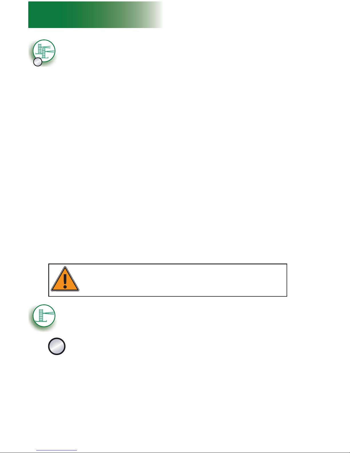
28
1 - MOTORIZED UNIT
B
Setup and confi gurations
Multiple units confi guration with mast ties – pre-installation
Installation of mast sections and mast ties
9- Using a crane or a rough terrain forklift, load mast sections on the units. Mast
sections should be stored horizontally and distributed equally on each motorized
unit to ensure good balance. Refer to the Load Capacities section on p. 80 for
more information about loading the units.
10- Install mast sections until a fi rst tie level is required. Refer to p. 69 of the Mast and
Mast Ties section for instructions on how to install mast sections. It is important to
install mast sections alternately – on the fi rst motorized unit, then on the second, to
ensure good balance. For more information about the schedule of installation of tie
levels, refer to the Mast Tie Schedule table on p. 70 of the Masts and Mast Ties
section. Refer to p. 70 of the Masts and Mast Ties section for instructions on how
to install mast ties.
11- Install as many mast sections as the plan layout requires and as is allowed. A setup
with mast ties should not be raised above 250' (76 m). Make sure throughout the
process that each mast remains plumb on both its front and side axis and that tie levels
are installed when required.
12- It is important to make sure to verify the mast bolts on each mast when lowering the
platform to make sure they are tightened to the proper torque and are in good
condition, especially on brand-new mast sections, as the galvanized coating
may have compressed. In all cases, mast bolts must be tightened to a torque of
120 lb-ft (163 N-m). Failure to tighten bolts properly may lead to serious injury or
death.
Preparing for operation
13- Once all tie levels are in place, all accessories can be used and weather protection
tarps and shields, if required, can be installed.
14- Before authorizing workers to use the motorized unit, perform every step in the daily
inspection checklist. If required, fi ll out the handover sheet to complete the installation.
Refer to p. 120 of the T ransport, Storage and Maintenance section for more information
about the daily inspection checklist and to p. 124 for information about the handover
sheet.
WARNING
During pre-installation, when weather protection is required and allowed, only
the structure can be installed. Tarps and shields must only be installed once all
tie levels are in place up to the top of the work.
Single unit confi guration with mast ties – pre-installation
The following installation steps can be used for a non-standard confi guration
requiring additional equipment but no accessories other than a hoist. Refer
to fi g. 1.27, fi g. 1.28 and fi g. 1.29 on p. 22, for details about the restrictions
and allowances for a confi guration. Refer also to p. 17 of this section for more
information about standard and non standard confi gurations.
C
1- Prepare the motorized unit and the area where the setup will be installed as described
in the general guidelines on p. 18 (steps 1 through 15). Make sure that all base
outriggers are completely closed.
Positioning the motorized unit
It is important to note that cantilever bridges must not be installed until all tie
levels are in place.
(requires the use of two bearing bridge adapters – sold separately)

29
1 - MOTORIZED UNIT
Installation of the hoist
2- If required and allowed, install a hoist. It is important to note that during pre-installation,
the hoist can be used only to handle mast sections and cannot be used above the last
tie level installed. For information on the installation and use of the hoist, refer to
p. 103 of the Accessories section.
Setup and confi gurations
Single unit confi guration with mast ties – pre-installation
C
Verifi cation of the setup
3- Make a fi nal verifi cation of the setup before starting to install mast sections. Make
sure all the guardrails are in place and secure (see p. 91 of the Accessories section
for more information about guardrails). In all cases where workers are exposed to fall
hazards greater than specifi ed by local regulations, the installation of guardrails or
face guardrail supports is mandatory.
Installation of mast sections and mast ties
4- Using a crane or a rough terrain forklift, load mast sections on the unit. Mast
sections should be stored horizontally and distributed equally on the motorized
unit to ensure good balance. Refer to the Load Capacities section on p. 80 for
more information about loading the platform.
5- Install mast sections until a fi rst tie level is required. Refer to p. 69 of the Mast and
Mast Ties section for instructions on how to install mast sections. It is important to
install mast sections alternately – one on one mast, then one on the other, to ensure good
balance. For more information about the schedule of installation of tie levels, refer to
the Mast Tie Schedule table on p. 70 of the Masts and Mast Ties section. Refer to
p. 70 of the Masts and Mast Ties section for instructions on how to install mast ties.
6- Install as many mast sections as the plan layout requires and as is allowed. A setup
with mast ties should not be raised above 250' (76 m). Make sure throughout the
process that each mast remains plumb on both its front and side axis and that tie levels
are installed when required.
7- It is important to make sure to verify the mast bolts on each mast when lowering the
platform to make sure they are tightened to the proper torque and are in good
condition, especially on brand-new mast sections, as the galvanized coating
may have compressed. In all cases, mast bolts must be tightened to a torque of
120 lb-ft (163 N-m). Failure to tighten bolts properly may lead to serious injury or
death.
Installation of bridges and additional equipment
8- With the motorized unit at base level, install as many bridges as is required and
allowed. For instructions on how to install a bridge, refer to p. 43 of the Bridges section.
Refer to the Load Capacities section on p. 80 for the maximum number of bridges
allowed in a setup. It is important to note that loads cannot be applied on bridges
during pre-installation.
9- Install additional equipment as is required and allowed. For information about the
combined use of equipment and accessories allowed for a confi guration, refer to the
Combination of Standard and Non Standard Confi gurations table in fi g. 1.24, p. 17.
For instructions on the installation and use of forward extension or swivel bridges,
refer to the Bridges section on p. 43.
Installation of outriggers and planking
10- Adjust the outriggers and install planks, as required and allowed (see p. 95 of the
Accessories section for more information).
Preparing for operation
11- Once all tie levels are in place, the hoist can be used as required.
12- Before authorizing workers to use the motorized unit, perform every step in the daily
inspection checklist. If required, fi ll out the handover sheet to complete the installation.
Refer to p. 120 of the T ransport, Storage and Maintenance section for more information
about the daily inspection checklist and to p. 124 for information about the handover
sheet.
 Loading...