

Hydro Mobile F200, F300 Owner's Manual

Owner’s Manual
for gas-powered and electrical
unit models F200 and F300
Call us for information:
1-888-484-9376 (US)
(toll free in the United States)
(450) 589-8100 (Canada)
21053002-0-00000-0
F2_OpMan_v2.02_EN
© 2018 by Hydro Mobile, a division of AGF Access Group, Inc. All rights reserved
This manual was produced by Hydro Mobile on Adobe® InDesign CC® version 13.1 x64 for Windows®.
Technical drawings were prepared using Autodesk Inventor ® 2017. Illustrations were created with Autodesk Inventor ®
2017, Adobe® Illustrator CC® version 22.1 for Windows® and Adobe® Photoshop CC ® version 19.1.5 for Windows®.
This manual may not, in whole or in part, be copied, photocopied, reproduced, translated, or converted to any electronic
or machine readable form without prior written consent of Hydro Mobile
All assembly and operation instructions located on motorized units and bridges take precedence over information
contained in this manual. Should there be any discrepancies discovered throughout any published documentation
issued by Hydro Mobile or its authorized affi liates, the following order of precedence shall prevail:
1. Written documents issued by the Hydro Mobile Engineering department
2. Recall instructions
3. Assembly or operation instructions displayed on the motorized unit
4. Owner's manual
Any use of one or several Hydro Mobile motorized units, with or without accessories, in such a confi guration
or manner as not explicitly described in this manual is prohibited without the prior written permission of
Hydro Mobile.
NOTE
Code / Version Date Description
Changes to control panel section; inclusion of accessories (adapter bases for
freestanding installation and installation with sidewalk canopy, monorail, hoist);
addition of defi nitions for competent person and for qualifi ed person; addition
of defi nition of standard confi guration; addition of the authorized combination of
equipment and accessories for linked confi gurations and restrictions for unlinked
21053002-00000-0
V00
V01 Feb 2018
V02 Sept 2018
Sept 2017
confi gurations; addition of methods of installation of tie levels with related subdivided
instructions for the assembly and for the dismantling of an installation; addition of
authorized non standard planking confi gurations; subdivision of mast tie schedules
for each method of installation of tie levels; addition of instructions for the removal
of mast sections and of mast ties; addition of wall ties and installation guidelines for
authorized wall and fl oor ties; changes to authorized bridge confi gurations at opposite
ends of unit for specifi c bridge installations; addition of safety accessories subdivision;
addition of multiple mast handler; detailed information about inspection checklists;
sample views of checklists, including job survey and installation handover sheet
Various typo corrections; inclusion of some missing metric conversions;
clarifi cation for procedures or instructions (emergency descent, startup
preparation instructions, installation of additional rigid dual clamps, cantilever
reinforcement cable retainer); change to load capacities of multiple units
unlinked installation (45' or 14 m setup, rightmost bridge)
Changes to emergency descent instructions; inclusion of lock bracket for swivel
counterweight adapter
LEGEND OF ICONS
These icons are used to highlight important information throughout this manual
Information
Useful information for safe and easy operation
Useful tip
A useful tip to facilitate installation or operation
Type of setup
Single unit freestanding installation
Type of setup
Multiple units freestanding installation
The information and
instructions contained in this
manual applies to units bearing
the following serial numbers
Model F200 F200-0082 and up
Model F300 F300-0100 and up
F Series motorized units and
overspeed safety devices (OSD) are
protected by the following patents:
Canada
Unit: patent # 2370398
OSD: patent # 2547286
United States
Unit: patent # 6523647
OSD: patent # 7909142
Revision List
Warning note
An important warning: damage or injury may occur
Wind speed warning
An important warning: wind speed conditions must
be observed to avoid damage or injury
Type of setup
Single unit installation with mast ties
Type of setup
Multiple units installation with mast ties
G I
Motorized unit serial number
Manufacturing date
F200 19' (5.8 m)/min motorized unit
F300 38' (11.6 m)/min motorized unit
www.hydro-mobile.com
125 de l’Industrie
L’Assomption, Quebec,
Canada J5W 2T9
For orders or information:
1-888-484-9376 (US)
(toll free in the United States)
450 589-8100 (Canada)
21053002-0-00000-0

G I
General Information
Performance and Safety
1 – Motorized Unit
3 – Bridges
4 – Power Pack and Components
7 – Load Capacities
5 – Control Panel
6 – Mast and Mast Ties
6 – Mast and Mast Ties
8 – Accessories
2 – Safety Devices
9 – Transport, Storage and Maintenance
TABLE OF CONTENTS
TABLE OF CONTENTS
General Information
Introduction .........................................................................................5
Warranty ............................................................................................6
Performance and safety rules.............................................................7
Overview ..........................................................................................10
List of components included with shipped unit .................................11
Toolbox components.........................................................................11
Motorized unit specifi cations ............................................................12
Weight of components ......................................................................14
Dimensions .......................................................................................15
Positioning
Minimum bearing surface capacities ............................................16
Recommended cribbing ................................................................16
Setup and confi gurations
General guidelines ........................................................................17
Combination of equipment and accessories
Combinations allowed for single and multiple units
linked confi gurations .............................................................17
Restriction of equipment and accessories allowed on each
cantilever side of an unlinked confi guration
(single or multiple units) .......................................................18
Restriction of equipment and accessories allowed on each
bearing bridge of an unlinked confi guration ..........................18
Defi nition of a standard confi guration ...........................................20
Methods of installation ..................................................................20
Single unit setups with mast ties
Method “A” – progressive installation of standard single unit ........20
Method “B” – pre-installation of a single unit installation ......23
Multiple units setups with mast ties
Method “C” – pre-installation of a multiple units installation .......26
Method “D” – pre-installation of a multiple units installation ......30
Splitting a motorized unit (F300 unit model only) .........................34
Dismantling an installation
Safety guidelines ......................................................................36
Single unit installed using method “A” ......................................36
Single unit installed using method “B” ......................................37
Multiple units installed using method “C” ..................................39
Multiple units installed using method “D” ..................................40
Emergency descent control system
Procedure for a single unit installation ..........................................43
Procedure for a multiple units installation .....................................44
Overspeed safety device ..................................................................46
Inclinometer
Connection ...................................................................................46
Detection of a ± 2-degree slope ...................................................47
Detection of a ± 5-degree slope ...................................................47
Adjustment of the 0° level position ...............................................47
Testing the inclinometer ................................................................48
Verifi cation of limit switches and panel alerts ...............................48
Fall protection ..........................................................................................49
Standard bridge
Installation of a bridge ..................................................................50
Storage of a bridge .......................................................................50
Bridge types......................................................................................51
Cantilever .........................................................................................52
Bearing bridge
Safety guidelines ..........................................................................52
Assembly of a bearing bridge structure ........................................52
Installation of a twin mast adapter ................................................52
Installation of the bearing bridge structure ...................................53
Dismantling a bearing bridge structure .........................................53
Forward extension bridge .................................................................54
Bridge deck extension ......................................................................55
Swivel bridge
Installation ....................................................................................56
Angle adjustment ..........................................................................56
Installation of swivel bridge guardrails ..........................................57
Front cantilever confi gurations .....................................................58
Back cantilever confi gurations ......................................................59
Front bearing bridge confi gurations ..............................................61
Back bearing bridge confi gurations ..............................................63
Counterweight adapter .................................................................65
Outrigger support assembly .........................................................67
Gas-powered unit
Startup preparation instructions ....................................................69
Motorized unit startup procedure ..................................................70
Engine shutdown procedure .........................................................70
Electrical unit
Startup preparation instructions ....................................................71
Power cable selection chart ..........................................................72
Motorized unit startup procedure ..................................................73
Motorized unit shutdown procedure .............................................73
Description........................................................................................74
Controls ..........................................................................................75
Screen alerts and instructions
Unlocking the display screen ........................................................76
Main menu screen ........................................................................76
F1 – Status info ............................................................................77
F2 – Alerts ....................................................................................77
F3 – Inputs and outputs ................................................................82
F4 – Confi guration ........................................................................83
Mast sections
Installation ....................................................................................84
Loading mast sections on the platform .........................................85
Removal and transport of mast sections ......................................85
Performance and Safety
1 – Motorized Unit
2 – Safety Devices
3 – Bridges
4 – Power Pack and Components
5 – Control Panel
6 – Mast and Mast Ties
6 – Mast and Mast Ties
Mast ties
General guidelines ........................................................................85
Installation of standard mast ties ..................................................86
Methods of installation of tie levels ...............................................89
Mast tie schedules
Methods of installation ..............................................................87
Without lateral base extensions ................................................87
With lateral base extensions .....................................................87
Location of perpendicular mast ties ..............................................88
Recommended order of installation ..............................................88
Installation of mast ties with extensions .......................................89
Additional rigid dual clamps ..........................................................89
Mast tie requirements for plank confi gurations .............................90
Wind speeds .................................................................................90
Removal of mast ties ....................................................................91
Anchoring system
Installation of wall ties ...................................................................91
Wall tie reactions ..........................................................................92
Wall tie types ................................................................................92
Wall tie distance for vertical anchoring installation .......................92
Installation guidelines
Horizontal anchoring .................................................................93
Fixed wall ties ...........................................................................93
Welded wall tie on a beam ........................................................93
Re-usable wall tie .....................................................................93
Load capacity calculation guidelines ................................................94
Calculating the maximum number of workers for an installation...............94
Linked confi gurations
Single unit installation ...................................................................95
Multiple units installation ...............................................................96
Unlinked confi gurations
Single unit installation ...................................................................97
Multiple units installation ...............................................................98
Forward extension installation
Using a standard bridge ...............................................................99
Using a multi purpose bridge ........................................................99
Swivel bridge installation
Single unit (0-45 degrees) ............................................................99
Single unit (90 degrees) .............................................................100
Multiple units ...............................................................................101
With counterweight adapter – three bridges ...............................102
With counterweight adapter – two bridges .................................103
Hoist installation
Single unit setup .........................................................................104
Multiple units setup .....................................................................105
Cantilever reinforcement cable retainer installations
Single unit installation .................................................................106
Multiple units installation .............................................................107
Safety Accessories
Guardrails
Installation of a standard guardrail ..........................................108
Face guardrail supports ..........................................................108
Movable guardrail ...................................................................109
Plank-end guardrail .................................................................109
Universal plank safety support ................................................109
Access stairs ..................................................................................110
Bridge installation support brackets................................................110
Outriggers
Description ..................................................................................111
Planking confi gurations
Outrigger selection table ......................................................... 111
Planking confi guration guidelines ........................................... 111
Doubled outriggers .....................................................................112
Outriggers required for doubling ............................................. 112
Cross boxes ................................................................................113
Non standard planking confi gurations
Non standard planking confi guration #1 .................................113
Non standard planking confi guration #2 .................................114
Non standard planking confi guration #3 .................................114
Outriggers – top position ............................................................115
Outriggers – bottom position ......................................................115
Multiple mast handler .....................................................................116
Adapter base for freestanding installation
Installation of the adapter base ..................................................117
Installation of the motorized unit on the adapter base ................117
Authorized height for freestanding installation with adapter base ...118
Jib arm
Installation of the jib arm on the motorized unit .......................... 119
Using the jib arm to lift a mast section ........................................120
Maximizing the use of a single jib arm ........................................120
Hoist support assembly ..................................................................121
Monorail ........................................................................................122
Weather protection for bridges .......................................................123
Cantilever reinforcement cable retainer..........................................124
Adapter base for sidewalk canopy installation
Installation of the adapter base ..................................................126
Minimum bearing surface capacities for an installation
with a sidewalk canopy ...........................................................126
Calculating distance from wall ....................................................127
Installation of the motorized unit on the adapter base ................128
Dismantling guidelines ................................................................128
Hydraulic oil heater / recirculator ....................................................129
Transport and storage
Preparation of the motorized unit ...............................................130
Lifting and moving a motorized unit or a setup
Using the forklift pockets on the mast head ............................131
Using the shackle on the mast head .......................................131
Storage of a motorized unit ........................................................131
Storage of a bridge .....................................................................132
Storage of mast sections ............................................................132
Inspection and maintenance
Greasing of gears and racks ......................................................133
Inspections .................................................................................134
Samples of checklist ...................................................................136
7 – Load Capacities
8 – Accessories
9 – Transport, Storage and Maintenance

G I
Introduction
Dear owner or user:
Thank you for investing in a Hydro Mobile F2 Series mast climbing work platform system
(models F200 and F300). The design of these motorized units refl ects over a decade
of continued fi eld operation, testing and research work and comes as a solution to our
company’s deepest concern, your safety and well being on the job.
To ensure that the workplace becomes safer and more effi cient using a Hydro Mobile
system, always have appropriately trained personnel assemble, operate, dismantle and
move your mast climbing work platform system. These qualifi ed persons will be required
to read this owner’s manual and assimilate the information contained herein. Failure to do
so could lead to serious injury and/or equipment damage.
These motorized units were designed in accordance with the following standards:
ANSI A92.9-2011, CAN/CSA B354.9-17, IS O 16369:2007 and EN 1495. Furthermore, these
US
motorized units and the owner’s manual comply with US ANSI A92.9-2011 standards, Federal
Occupational Safety and Health Administration Standards OSHA 29CFR1926 subpart L; with
ISO 16369:2007, CAN/CSA B354.10-17 and CAN/CSA B354.11-17; and with EN 1495.
To maximize the life expectancy of your equipment and to enjoy years of trouble free
operation, this Hydro Mobile system must be serviced according to maintenance schedules
and recommendations provided in this manual. It is also advised to refer to the engine or
motor user’s manual included with the motorized unit.
Should you have any questions or concerns, please contact the nearest authorized service
center or Hydro Mobile directly at 888-484-9376 (in the United States) or 450 589-8100 (in
Canada). You can also visit our Web site at www.hydro-mobile.com for additional support
and information on our factory safety and performance training seminars.
We wish you years and years of safe, productive construction and renovation work.
Sincerely,
Vincent Dequoy
President

G I
Warranty
Warranty period
Hydro Mobile, a division of AGF Access Group, Inc., herein referred to as Hydro Mobile, warrants
its new F2 Series motorized units (models F200 and F300) to be free from defect of materials and
workmanship for a period of 15 months or a maximum of 650 operating hours whichever occurs fi rst
from the date of delivery to the authorized distributor/service center.
Hydro Mobile also warrants its new F2 Series parts and accessories to be free from defect of
materials and workmanship for a period of 15 months from the date of delivery to the authorized
distributor/service center.
Product registration
In accordance with standards governing mast climbing work platform systems, the owner of a
Hydro Mobile F2 Series unit must register the product with Hydro Mobile within sixty (60)
days. The initial buyer of a Hydro Mobile F2 Series unit is automatically registered by Hydro Mobile.
Hydro Mobile must be kept informed of any change of ownership. The new owner must provide
Hydro Mobile with a full name and address, along with the model and serial number of the unit
acquired.
Description of warranty
Parts and accessories manufactured by Hydro Mobile
Hydro Mobile’s obligation and liability under this warranty are expressly limited to repairing or
replacing with re-manufactured or new parts, at Hydro Mobile’s option, any part and accessory
manufactured by Hydro Mobile proven defective after inspection by Hydro Mobile which appear to
have been defective in material or workmanship. Only permanent repairs will be covered under this
warranty. Hydro Mobile reserves the right to ask for maintenance records of the defective part before
settling a claim and to deny such claim if maintenance records are not available or not compliant
with maintenance schedules.
This warranty shall not apply to component parts or accessories of products not manufactured by
Hydro Mobile and which carry the warranty of the manufacturer thereof or to normal maintenance
(such as engine tune-up) or any part necessary to perform such maintenance. Hydro Mobile off ers
no other warranty, expressed or implied, and off ers no warranty of merchantability or fi tness for any
particular purpose.
Engine
All engines manufactured by Honda under the “GX” lineup are covered by an international warranty
of 36 months (12 months on muffl ers) and 36 months for Toshiba electric motors. To have an engine
repaired under this warranty, the engine must be brought to an authorized Hydro Mobile distributor
or to an authorized Honda or Toshiba service center.
Battery
All the batteries shipped from the factory with new equipment are guaranteed for a period of 60 days.
Any battery discharged due to operator error will not be covered under this warranty. Dead batteries
that can be recharged will not be replaced under this warranty.
Costs and liability associated with warranty
Hydro Mobile’s obligation under such warranty shall not include duty, taxes or any other charge
whatsoever, or any liability for direct, indirect, incidental or consequential damage or delay.
Exclusion
Any use of one or several Hydro Mobile motorized units, with or without accessories, in such a
confi guration or manner as not explicitly described in the owner’s manual is prohibited without the
prior written permission of Hydro Mobile.
Any improper use, including operation after discovery of defective or worn parts, shall void this
warranty. Improper use also includes operation beyond rated capacity, substitution of parts other than
those approved by Hydro Mobile, including anchor systems, or any alteration, modifi cation or repair
by others in such manner as in Hydro Mobile’s judgment aff ects the product materially and adversely.
Labor
All warranty work must be performed by a certifi ed Hydro Mobile technician to be eligible for
reimbursement under the warranty.

P S
Performance and Safety Rules
SAFETY comes fi rst. The installation and operation of a mast climber is subject to hazards that
can be avoided only by using extreme care and common sense, and by providing the appropriate
training and supervision to all its users.
It is essential that the installation and dismantling of an F2 Series motorized unit and its related
accessories be carried out according to the guidelines, instructions and warnings included in
the owner’s manual and performed by qualifi ed erectors/dismantlers under the supervision
of a competent person (see boxes below).
It is also imperative that the operation of an F2 Series motorized unit setup be carried out
according to the guidelines, instructions and warnings included in the owner’s manual. To ensure
safe and proper operation, Hydro Mobile recommends that two persons be on hand to perform
maneuvers for each motorized unit in a setup and that at least one of those two persons
is a qualifi ed operator (see box below).
WARNING
The F2 Series confi gurations and the methods used to achieve these confi gurations as
shown and described in this owner’s manual are the only ones authorized by Hydro Mobile.
For any confi guration or method to achieve such a confi guration other than those shown and
described in this owner’s manual, contact the distributor/service center.
WARNING
It is mandatory to refer to the Mast Tie Schedule tables on p. 87 of the Mast and Mast Ties
Competent person means a person who is capable of identifying existing and predictable hazards in
the surroundings or working conditions which are unsanitary, hazardous or dangerous to employees,
and who has authorization to take prompt corrective measures to eliminate them.
Defi nition of the qualifi ed person
“Qualifi ed” means a person who, by possession of a recognized degree, certifi cate or professional
standing, or who by extensive knowledge, training and experience, has successfully demonstrated the
ability to solve or resolve problems relating to the subject matter, the work or the project.
Only a qualifi ed person on the specifi c make and model of the Hydro Mobile equipment can carry out
the following tasks:
User/operator
A qualifi ed user/operator is allowed to operate Hydro Mobile units according to the guidelines, instructions,
warnings and methods set out in the owner’s manuals and Hydro Mobile training courses and after they
have been erected, tested and passed for use by a qualifi ed person.
Erector/dismantler
A qualifi ed erector/dismantler is allowed to erect, dismantle, test, pass for use and modify the
confi guration of Hydro Mobile units according to the guidelines, instructions, warnings and methods set
out in the owner’s manuals and Hydro Mobile training courses.
Technician
A qualifi ed technician is allowed to perform maintenance inspections and repairs on Hydro Mobile units
according to the guidelines, instructions, warnings and methods set out in the owner’s manuals and Hydro
Mobile training courses.
section before the installation of any F2 Series confi guration.
Defi nition of the competent person
Hydro Mobile recommends that Qualifi ed Persons follow the Hydro Mobile University Training
Program on the specifi c task and specifi c make and model to get proper qualifi cations. For more
information on the Hydro Mobile University Training Program,
visit www.hydro-mobile.com/training.
General guidelines
1- Prepare a layout plan showing how the mast climbing work platform system (motorized units,
bridges and accessories) will be positioned near structures or walls to be erected. On long
walls, install separate mast climber sections to allow for fl exibility. Make sure to position
motorized units so as to provide proper anchoring points for masts for tied installations.
2- Rely on a licensed engineer for help on special jobs and to approve plans if required by
local regulation.
3- It is recommended to use the job survey form as a guide for the proper installation of the
confi guration. Refer to p. 136 of the Transport, Storage and Maintenance section for more
information about the job survey form.
7

P S
Performance and Safety Rules
4- It is mandatory to refer to the Mast Tie Schedule tables on p. 87 of the Mast and Mast Ties
section and to the Load Capacities section on p. 94 before the installation of any F2 Series
confi guration.
5- Establish the distance between the mast climbing work platform system and the structure
or wall, taking into account the length of plank outriggers, as well as curvatures, balconies,
columns, trees, telephone wires, electrical lines, etc.
6- Refer to and follow local regulations governing distances between the mast climbing work
platform system and electrical lines. As a reference, North American regulations generally
recommend keeping a safe distance of at least 10' (3 m) from overhead power lines carrying
50,000 volts or less.
7- Make sure the ground or support surface capacity meets with values included in the Minimum
Bearing Surface Capacities table herein (fi g. 1.21, p. 16). Soil compacting, cribbing or
shoring can increase bearing capacity. The jacks on the base extensions are designed to
level the motorized unit and must not be used to support the load nor the motorized unit.
8- Never modify the mast climbing work platform system or use substitute factory parts. This
could adversely aff ect worker safety, unit performance and void the warranty. In addition,
this could lead to serious injury or death.
9- The F2 Series motorized unit (all models) must not be used with any equipment or any
accessories not specifi cally manufactured and rated by Hydro Mobile to be used with
F2 Series motorized units. For the use and installation of any such equipment or accessories,
contact the distributor/service center.
10- Each F2 Series motorized unit must be equipped with an appropriate fi re extinguisher (not
supplied). Use the support supplied with the motorized unit to hang the fi re extinguisher in
a readily accessible location (fi g. 1.1, p. 10).
11- Never use a gas-powered motorized unit in a enclosed space due to carbon monoxide
emissions or in a place where explosives are stored.
12- It is recommended not to smoke on the platform.
13- Planks used for planking must be scaff old graded (
regulations.
14- IMPORTANT: It is strongly recommended not to use equipment that generates vibrations
or reactions on Hydro Mobile platforms.
15- Workers exposed to potential hazards must always wear proper personal protection
equipment (
by local regulations. In all cases where workers are exposed to fall hazards, fall protection
is required. Installation of all the necessary guardrails is mandatory.
16- The F2 Series motorized unit (all models) must not be used on a mast with a height over
500' (152 m).
17- To ensure work effi ciency, maintain an adequate equipment and parts inventory on the job
site. Keep equipment in good condition.
18- Inspection and maintenance operations must be carried out effi ciently and in a timely
manner. Daily inspections and their related operations must be performed by a qualifi ed
user/operator every day or before every working shift. Frequent and annual inspections
and their related operations must be carried out by a qualifi ed technician. Refer to p. 133
of the Transport, Storage and Maintenance section for more information on inspection and
maintenance requirements for F2 Series motorized units and their accessories.
19- The qualifi ed erectors/dismantlers in charge of the installation must make sure that the
equipment being installed has been duly inspected and meets all applicable safety standards.
20- After installation, mark off limit areas of the system using fencing, barriers, warning tape
and note emergency phone numbers (fi re and police dept.) for quick reference. Prepare an
emergency evacuation plan that is specifi c to the job site and is in accordance with
local regulations.
PPE) such as a helmet, safety boots, a fall arrest harness, etc., as prescribed
SPF), in good condition and meet local
8

P S
on
Performance and Safety Rules
21- Never load bridges or motorized units beyond their rated capacities. Overloading may
bring damages to equipment or cause the installation to become unbalanced, leading to
serious injury or death.
22- Contact the distributor/service center for service, repair or technical advice. Refer to
equipment type and serial number when calling.
23- Each person must access the platform using a safe means of access such as an optional
access stairs, a transport platform system, stairways or through an opening in the building.
In all cases, transfer must be safe and free from obstruction.
24- The use of appropriate fall protection equipment is mandatory when modifying plank
confi guration or whenever the worker is exposed to a fall hazard. Failure to use fall protection
equipment can expose the user to serious injury or death. Refer to local regulations for
more information.
25- When the motorized unit is moving, it is mandatory that all workers except the operator
stand in an area close to the rear guardrails.
26- In the event of an abnormal occurrence or operation which could compromise security
(ex. malfunction of a motorized unit component, collision with an obstacle, etc.), immobilize
the unit and inform the competent person.
27- It is strongly recommended not to touch any of the moving parts on the motorized unit when
it is in use.
28- All access doors and panels on the motorized unit must be closed when they are not in use.
All access doors and panels must be free from any material or obstruction.
29- The motorized unit must not be used or operated during an electrical thunderstorm. The
motorized unit and its components must not be used as ground for electrical connections.
30- The deposit of loads on the setup must be done with extreme care and under proper supervision.
Loads must be distributed on all the bridges of the setup, as prescribed by the load capacities
charts. Refer to the Load Capacities section on p. 94 for more information about placing
loads on the platform. When the motorized unit setup is not in use and above base level,
loads should not be left on the platform except for counterweights. When a tied installation
is not in use, it is mandatory to leave the platform between two tie levels.
31- On a setup using an F2 Series electrical unit, it is important to note that in the event
of a power outage, it is recommended that all workers remain on the platform as a
safety precaution until the power is restored. If the power has not been restored within a
reasonable time, the emergency descent system must be used to bring the workers safely
back to the nearest safe evacuation point. Refer to p. 43 of the Safety Devices section
for more information on the use of the emergency descent system.
WARNING - WIND SPEEDS
The erection and dismantling of a motorized unit setup (including the base, the
bridges, the masts, the mast ties and all the other components) must not be conducted
when wind speeds exceed 28 mph (45 km/h). Freestanding installations and
setups equipped with weather protection, when allowed, must not be used with
wind speeds exceeding 28 mph (45 km/h). Weather protection, when allowed,
must not be used when work is performed on an open air structure. A motorized
unit setup with mast ties must not be operated when wind speeds exceed
35 mph (56 km/h). If wind speeds are expected to exceed 102 mph (164 km/h),
the motorized unit must be brought down to base level.
When a freestanding installation is not in use:
• The motorized unit must be brought down to base level
When a tied installation is not in use:
• It is mandatory to leave the platform between two tie levels
• All loads must be removed from the setup, except all counterweights applied on
the setup
9
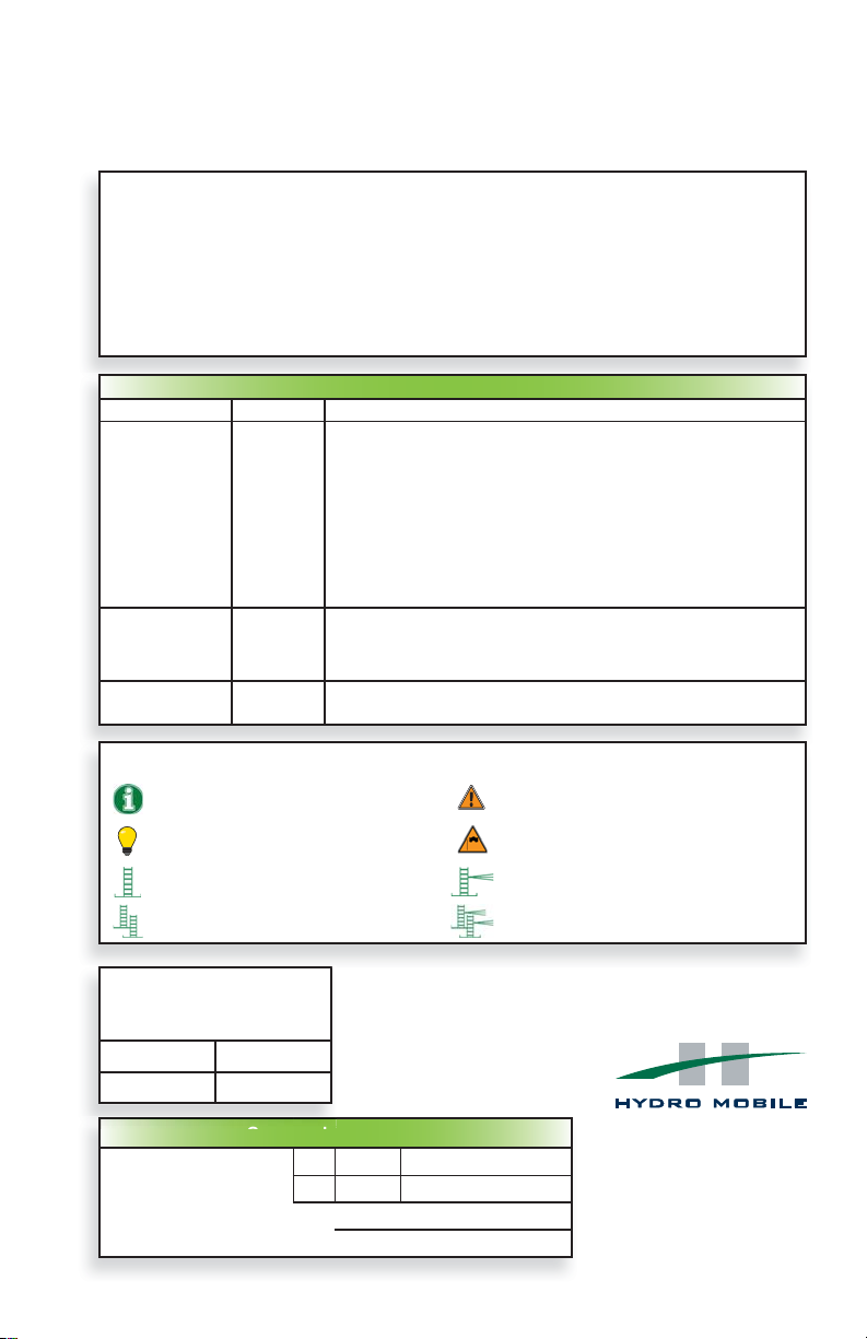
1 - M U
Motorized Unit Overview
Main
trolley
Link bridge
guardrail
Link bridge Link bridge
Power train
Link bridge
door
Mast section *
Base extension
Support for fi re
extinguisher
Trolley link
Mast head
Adjustable jack
Mast guard
Power train
Base
(including
welded bottom
mast section)
Control panel
and engine
controls
Main
frame
27" (69 cm)
guardrails
Door guardrail
63" (1,6 m)
outrigger
60" (1,5 m)
guardrail
Guardrail
adapter
fi g. 1.1
* Only one full mast section shipped with each motorized unit
The mast confi guration represented in the above illustration is for informational purposes only and must not be
reproduced without appropriate cribbing under the base. Models F200 and F300 of the Hydro Mobile F2 Series
motorized units come equipped with the components shown in fi g. 1.1, with features specifi c to each model,
as described below.
Note: Items depicted in illustrations may diff er from actual products.
10
F200 model basic features
• Mast with two racks
• One power pack
• Two power trains
• Up to 19' (5,8 m)/min climbing speed
• Capacity of up to 9000 lb (4082 kg) at 50' (15,2 m )
for a single unit installation
• Linked confi guration only
F300 model basic features
• Mast with two racks
• Two power packs
• Two power trains
• Up to 38' (11,6 m)/min climbing speed
• Capacity of up to 9000 lb (4082 kg) at 50’ (15,2 m)
for a single unit installation
• Linked or unlinked confi guration
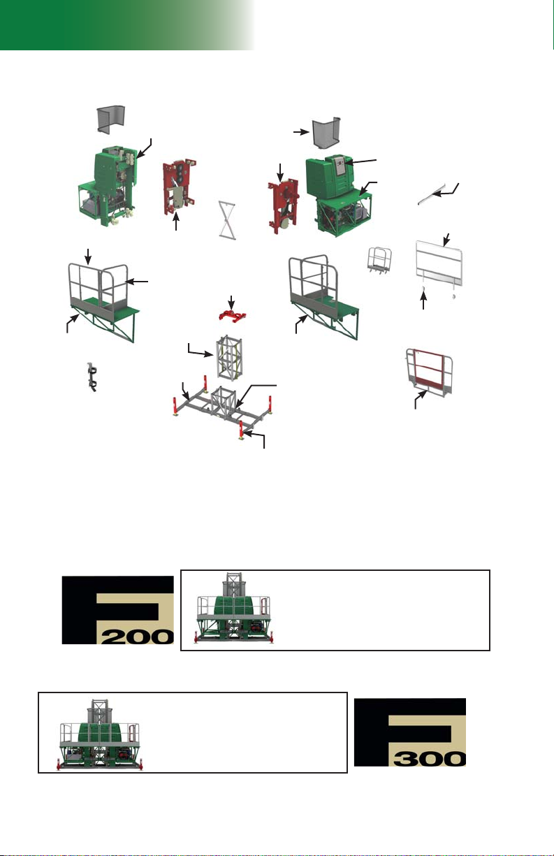
List of components
included with shipped unit
Main
Toolbox Components
trolley
Power
train
Overspeed
safety
device
fi g. 1.2
Hydraulic tank tubes
Motorized Unit Overview
Main
frame
Engine
controls
Gas-powered motorized unit
Engine
1 - M U
Mast guard
Display screen
Gasoline
tank fi ller
cap
Access
panels
Gas tank
fi g. 1.4
Lifting mechanism
List of components
included with shipped unit
Qty Component
F2 Series motorized unit (gas-powered or electrical)
1
(model F200 or F300)
1 base
base extensions
2
(left and right)
1 mast section
2 mast guards
1 mast head
2 link bridge guardrails
link bridge doors
2
(model F300 only)
communication cable
1
(model F300 only) (A0500603-0021)
support for fi re extinguisher
1 or 2
(according to
1x for F200 model
unit model)
2x for F300 model
1 60" (1,5 m) guardrail
2 27" (69 cm) guardrails
6 guardrail adapter brackets
1 door guardrail
4 63" (1,6 m) outriggers
Note
The list of components included with each motorized unit
shipped may change without notice.
fi g. 1.5
fi g. 1.7
fi g. 1.3
Battery
Guide
rollers
Motor
fi g. 1.6
Quantity Description
2
2
1 Owner’s manual
1 Honda engine manual
1 pressure gauge (3000 psi)
1 mast shim
1 15/16" wrench
3 5/8" x 1 1/2" SAE bolts GR5
3 5/8" SAE GR5 square nuts
6 5/8" x 5 1/2” SAE bolts GR8
6 5/8" SAE GR8 nuts
6 5/8" SAE lock washers GR8
3 3/8" SAE toggle pins
3 1/8" x 2 5/8" hitch pin clips
3 plank stop pins
1 or 2
(according to
unit model)
Toolbox
Oil cooler
Electrical motorized unit
Toolbox
Oil cooler
Toolbox Components
12.5-oz (370 ml) aerosol cans
of grease for rack and pinion
bridge installation support
brackets
cable grip support kit (electrical unit
only)
1x for F200 model
2x for F300 model
Power box
fi g. 1.8
11

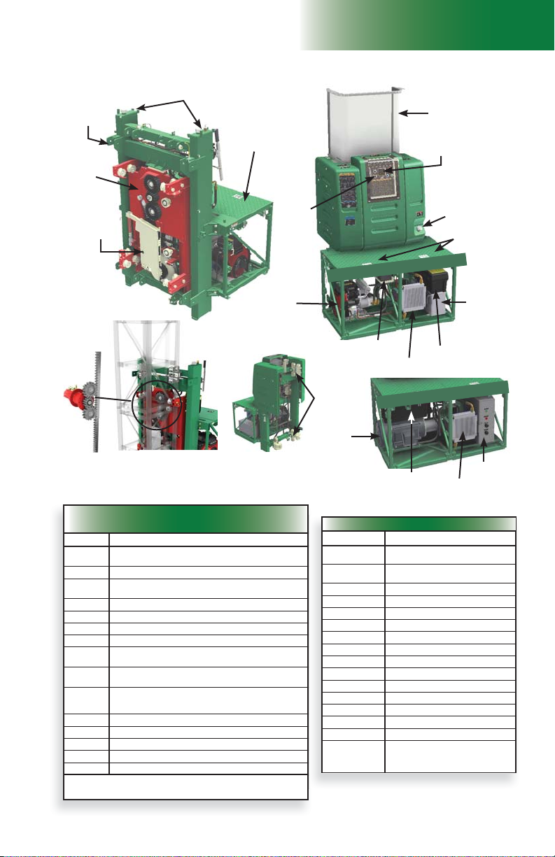
1 - M U
g
Specifi c Features
General Specifi cations
Hydraulic Specifi cations
Motorized Unit Specifi cations
General Specifi cations
On base, with extensions and
Dimensions of the motorized
unit
(as shipped)
Drive system Rack and pinion drive
Maximum height Up to 500' (152 m) of mast
Distance between tie levels Up to a maximum of 45' (13,7 m)
Freestanding height
Safety devices
with link bridges installed
On base, with extensions and
with link bridges removed
Up to 48' (15 m) of mast
using an optional adapter base for freestanding installation (when allowed)
Emergency descent Gravity-activated manual descent system
Overspeed safety device Independent mechanical device
Inclinometer (included with
twin mast adapter)
99 1/2" x 147 1/4" x 102" (W x L x H)
(253 cm x 374 cm x 259 cm)
75 1/2" x 147 1/4" x 102" (W x L x H)
(192 cm x 374 cm x 259 cm)
Analog electronic angle device
fi g. 1.9
fi g. 1.10
Specifi c Features
F200 F300
Gas-powered motorized
Platform weight
(as shipped)
Maximum load
capacity
Vertical travel speed Up to 19' (5,8 m) per minute Up to 38' (11,6 m) per minute
Mast section
Bridges
unit
Electrical motorized unit
Single unit installation
Multiple units installation
30" (76 cm)
(guardrail included)
5' (1,5 m)
(guardrail included)
10' (3 m)
(guardrail included)
Twin mast adapter
(guardrail sold separately)
On base
6700 lb (3030 kg)
On base
7200 lb (3266 kg)
9000 lb at 50'
(4082 kg at 15,2 m)
15,500 lb at 115'
(7031 kg at 35 m)
2 racks
32" x 32" x 60"
(81,3 cm x 81,3 cm x 152,4 cm)
365 lb (166 kg) per section
31" x 62" x 36" (W x L x H)
(0,8 m x 1,6 m x 0,9 m)
61" x 62" x 36" (W x L x H)
(1,5 m x 1,6 m x 0,9 m)
120" x 62" x 36" (W x L x H)
(3 m x 1,6 m x 0,9 m)
32" x 62" x 36" (W x L x H)
(0,8 m x 1,6 m x 0,9 m)
On base
8400 lb (3810 kg)
On base
9400 lb (4264 kg)
Hydraulic Specifi cations
Component Specifi cations
Double gear pump 2 x 7.25 US GPM (27,44 l/min)
Planetary reducer gear oil
Planetary reducer brake oil
Hydraulic tank capacity 18 US gal (68,2 l) model F200; 36 US gal (136,2 l) model F300
Hydraulic oil Shell Naturelle HF-M biodegradable product code 407-214
Oil fi lter (return) Mfr. model no. Ikron CSG-100-P10-A)
Oil fi lter (pressure) Mfr. model no. Ikron HEK85 20.8-AS-FG101-LC-V
Sunoco Challenge GBO 220 (product # 6048-020)
Warning: do not use in planetary reducer brake
Total Dynatrans MP-AS (product # 406435)
Warning: do not use in planetary reducer gear box
12
fi g. 1.11

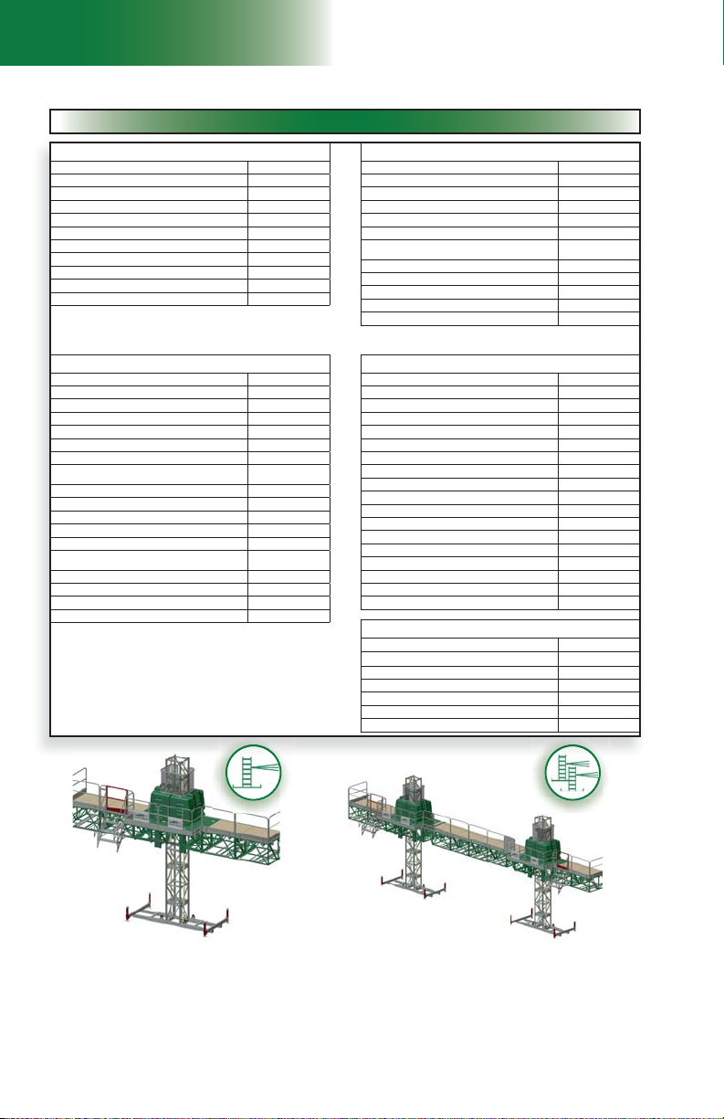
1 - M U
Engine Specifi cations (gas-powered motorized unit)
g
Operation Specifi cations
Wind exposure
Motor Specifi cations (electrical motorized unit)
Electrical Specifi cations
Requirements for complete F200 unit model and for each side of an F300 unit model
Motorized Unit Specifi cations
Engine Specifi cations (gas-powered motorized unit)
Model Honda GX630
Rated power 20.8 HP @ 3500 rpm
Fuel consumption 1.56 G/hr (6 l/hr)
Spark plug ZFR5F (NGK)
Oil type SAE 10W-30
Gasoline tank capacity 10 US gal (38 l)
Oil capacity 1,8 US qt (1,70 l)
Charging system 12 VDC - 17 ampere-hour
Battery 12 VDC
For any other information regarding the use and the maintenance of Honda engines,
refer to the Honda user’s manual
fi g. 1.12
fi g. 1.13
Motor Specifi cations (electrical motorized unit)
480 V unit 600 V unit
Brand Toshiba Toshiba
Model 0252SDSR42BP 0252SDSC42BP
Rated power 25 HP (18,5 KW) 25 HP (18,5 KW)
Service factor at full load 1,1 1,1
Rated amperage (nominal) 29A 23A
Power supply – voltage, phase and frequency 480 VAC / 3/60 600 VAC / 3/60
Rotation speed 3600 rpm 3600 rpm
fi g. 1.14
Electrical Specifi cations
Requirements for complete F200 unit model and for each side of an F300 unit model
Lifting power
Power consumption
(maximum load)
Starting current
unit) (peak)
Input power
Control voltage 12 VDC 12 VDC
Power outlet for hand tool 1 x 120VAC/20A/60 Hz 1 x 120VAC/20A/60 Hz
Cable up to 500' (152 m)
(per single
F200 model
Each side of F300 model
F200 model
Each side of F300 model
F200 model
Each side of F300 model
F200 model
Each side of F300 model
480 V unit 600 V unit
25 HP 25 HP
1 x 32A 1 x 25A
Up to 181A Up to 144A
480 VAC / 3 ph / 60 Hz
(± 5%)
1 x 6/4 1 x 8/4
600 VAC / 3 ph / 60 Hz
(± 5%)
fi g. 1.15
Operation Specifi cations
Wind exposure
Maximum wind speed allowed
During erecting and dismantling, when using
weather protection and in freestanding
confi guration using an optional adapter base for
freestanding installation (when allowed)
*
The platform must only be used on a mast whose height does not exceed 500’ (152 m)
During operation 35 mph (56 km/h)
When unit is out of service
28 mph (45 km/h)
102 mph (164 km/h) *
.
13
1 - M U
Weight of Components
Motorized Unit Specifi cations
Weight of Components
Description Weight
F300 Motorized unit (gas-powered, as shipped) 8400 lb (3810 kg)
F200 Motorized unit (gas-powered, as shipped) 6700 lb (3030 kg)
F300 Motorized unit (electrical, as shipped) 9400 lb (4264 kg)
F200 Motorized unit (electrical, as shipped) 7200 lb (3266 kg)
Base extension 275 lb (125 kg)
Base with extensions and one full mast section 1235 lb (560 kg)
Trolley link 60 lb (27 kg)
Link bridge (
Mast guard 30 lb (14 kg)
Mast head 125 lb (57 kg)
UNITS and components
LEFT or RIGHT) 165 lb (75 kg)
fi g. 1.16
BRIDGES (including guardrails)
Description Weight
30" (76 cm) bridge assembly 290 lb (132 kg)
5' (1,5 m) bridge assembly 390 lb (177 kg)
10' (3 m) bridge assembly 720 lb (327 kg
Swivel bridge assembly 800 lb (363 kg)
33" (84 cm) multi purpose bridge 310 lb (141 kg)
Twin mast adapter assembly
(without guardrail)
30" (76 cm) deck extension (with outrigger) 96 lb (44 kg)
33" (84 cm) deck extension (with outrigger) 102 lb (46 kg)
60" (1,5 m) deck extension (with outrigger) 124 lb (56 kg)
Swivel bridge counterweight adapter 175 lb (79 kg)
Swivel bridge outrigger adapter 60 lb (27 kg)
330 lb (150 kg)
Description Weight
Access stairs assembly 83 lb (38 kg)
Access stairs handrail 21 lb (10 kg)
Access stairs extension 25 lb (11 kg)
Jib arm complete assembly 140 lb (63 kg)
Jib arm top assembly 108 lb (49 kg)
Jib arm bottom assembly 32 lb (14 kg)
Hoist support structure
(including beam; hoist not included)
Weather protection – X brace (all lengths) 10 lb (4 kg)
Weather protection – frame truss extension 15 lb (7 kg)
Weather protection – frame assembly 85 lb (39 kg)
Weather protection – frame with extension 100 lb (45 kg)
Weather protection – center frame assembly 44 lb (20 kg)
Weather protection – frame truss extension
for monorail
Junction plate assembly 19 lb (9 kg)
Monorail beam 85 lb (42 kg)
Adapter base for freestanding installation 2500 lb (1134 kg)
Adapter base for sidewalk canopy installation 2000 lb (907 kg)
ACCESSORIES
485 lb (220 kg)
17 lb (8 kg)
fi g. 1.17
GUARDRAILS and OUTRIGGERS
Description Weight
27" (69 cm) guardrail (without adapter bracket) 32 lb (15 kg)
30" (76 cm) guardrail (without adapter bracket) 32 lb (15 kg)
33" (84 cm) guardrail (without adapter bracket) 33 lb (15 kg)
60" (1,5 m) guardrail (without adapter bracket) 50 lb (23 kg)
60" (1,5 m) door guardrail 100 lb (45 kg)
Guardrail adapter bracket 4 lb (2 kg)
Twin mast adapter guardrail 45 lb (20 kg)
Movable guardrail 65 lb (29 kg)
Plank-end guardrail 25 lb (11 kg)
Link bridge guardrail 59 lb (27 kg)
Swivel bridge “A” guardrail 16 lb (7 kg)
Swivel bridge “B” guardrail 42 lb (19 kg)
Swivel bridge “C” guardrail 49 lb (22 kg)
63" (1,6 m) outrigger 17 lb (8 kg)
72" (1,8 m) outrigger 27 lb (12 kg)
84" (2,1 m) outrigger 45 lb (20 kg)
120" (3,04 m) outrigger 55 lb (25 kg)
Description Weight
Mast assembly (2 racks) 365 lb (166 kg)
Mast assembly (1 rack) 330 lb (150 kg)
Mast tie frame 50 lb (23 kg)
Mast tie 36" (91 cm) 16 lb (7 kg)
Mast tie extension 36” (91 cm) 13 lb (6 kg)
Mast tie extension 60" (1,5 m) 20 lb (9 kg)
Mast and Mast Ties
Typical single unit installation
• One F2 Series motorized unit
• Two (2) 10' (3 m) bridges
Note: Access stairs and ramps shown in illustrations above are optional
14
fi g. 1.18
Typical multiple unit installation
• Two F2 Series motorized units
• Two (2) twin mast adapters
• Four (4) 10' (3 m) bridges
1 - M U
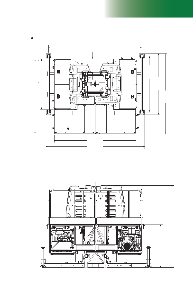
Dimensions of the Motorized Unit
Note: Unit dimensions are the same for both types of unit, gas-powered or electrical
Front
To wall
(78,3 cm)
30 13/16"
62"
92 5/8"
(157,5 cm)
(235,1 cm)
Link bridge
guardrail
Left Right
139 1/4"
(352,7 cm)
16 9/16"
(42,1 cm)
121 13/16"
(309,4 cm)
147 1/4"
(374 cm)
69 1/2"
(176,5 cm)
75 1/2"
(191,8 cm)
99 1/2"
(252,7 cm)
Back
Back
fi g. 1.19
52 7/8"
(134,3 cm)
fi g. 1.20
101 3/8"
(257,5 cm)
15
1 - M U
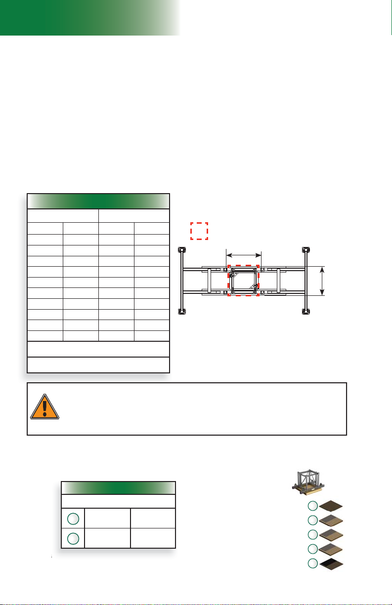
Minimum Bearing Surface Capacities
e o
Recommended Cribbing
Positioning the Motorized Unit
General Concept
Bearing surface
Before installing the motorized unit, make sure the bearing surface under it is level, clear of debris
and has the proper bearing capacity. Appropriate cribbing must be placed under the base to
distribute the load. It is important to make sure that the bearing surface is stable and has not been
subject to any type of erosion or deterioration caused by weather conditions (snow, rain, etc.).
The type of cribbing chosen may vary according to the bearing surface where the setup
must be installed.
For example, a setup installed on a concrete slab that is covering the bearing surface would
require cribbing consisting of only one plywood panel under the base while a setup installed on
a concrete slab that is covering an indoor garage would require shoring in addition to plywood
cribbing.
A setup installed on a bearing surface composed of gravel, sand or any such type of surface
would require stronger cribbing under the base.
In cases where shoring is required, it is recommended to contact an engineer for assistance.
Minimum Bearing Surface Capacities
Height Reaction
ft m lb kg
50 15 28 816 13 071
100 30 32 559 14 769
150 46 36 302 16 466
200 61 40 045 18 164
250 76 43 788 19 862
300 91 47 531 21 560
350 107 51 272 23 257
400 122 55 017 24 955
450 137 58 760 26 653
500 152 62 503 28 351
Note: Reactions shown in this table are for tied
installations only
Load reactions in table above include a dynamic
factor
fi g. 1.21
Mandatory cribbing area
32" (81,3 cm)
fi g. 1.22
32"
(81,3 cm)
Make sure the ground or support surface capacity meets with values included in the
Minimum Bearing Surface Capacities table (fi g. 1.21). Soil compacting, cribbing or shoring
can increase bearing capacity. Any cribbing product or cribbing method approved by the site
engineer can be used to distribute the load on the bearing surface providing it meets the
values in the Minimum Bearing Surface Capacities table (fi g. 1.21). Contact an engineer for
WARNING
assistance.
Recommended cribbing for most bearing surfaces
The plywood and lumber used as cribbing must be secured together to prevent slipping. Using
screws instead of nails for securing will prolong the service life of lumber and plywood used
as cribbing.
Recommended Cribbing
40" x 40" x 6"
Plywood
40" x 40" x 3/4"
1
(102 cm x 102 cm x 1,9 cm)
Lumber
2"x 10" x 40"
2
(5 cm x 25 cm x 102 cm)
Values shown in the above table are for reference only. Any cribbing that
hown in the above table are for referenc
covers the mandatory cribbing area (as shown in fi g. 1.22) can be used.
(102 cm x 102 cm x
15,2 cm)
2
12
fi g. 1.23
fi g. 1.24
3/4" (1,9 cm)
1 1/2" (3,8 cm)
1 1/2" (3,8 cm)
1 1/2" (3,8 cm)
3/4" (1,9 cm)
16
Plywood
Lumber
Lumber
Lumber
Plywood
1
2
2
2
1
1 - M U
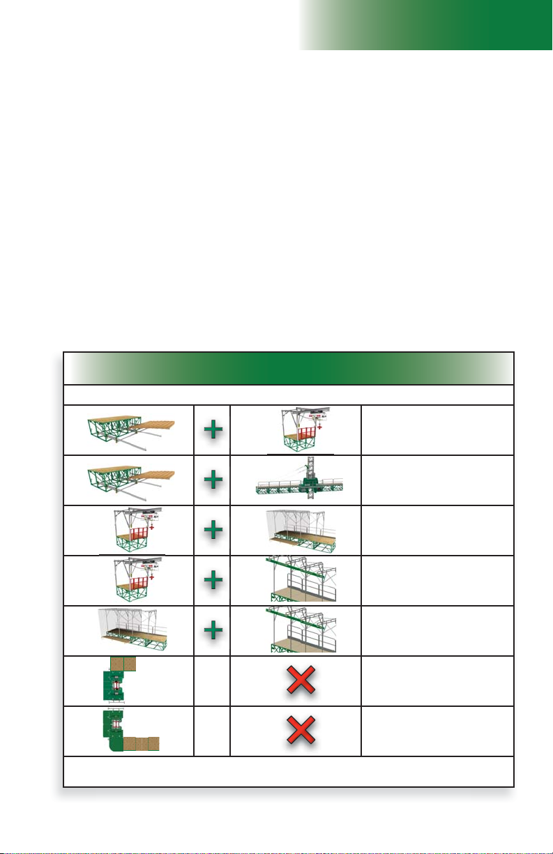
Combination of equipment and accessories allowed
LINKED CONFIGURATIONS – SINGLE UNIT and MULTIPLE UNITS
Setup and Confi gurations
General Guidelines
Setups with F2 Series motorized units and bridges require mast ties, unless an optional adapter
base for freestanding installation is used. The optional adapter base for freestanding installation
can only be used in a standard confi guration. A standard confi guration is a linked installation
that does not require the use of additional equipment, such as a forward extension bridge, a
swivel bridge, a planking confi guration wider than three planks, weather protection, a hoist, a
monorail or a cantilever reinforcement cable retainer.
It is mandatory to refer to the Mast Tie Schedule tables on p. 87 of the Mast and Mast Ties
section before the installation of any F2 Series confi guration, whether freestanding or tied.
It is important to consider that the combined use of equipment and accessories required to achieve
a confi guration may not be allowed on a same installation. For information on the combination of
equipment and accessories allowed for a linked confi guration, refer to the table in fi g. 1.25. For
information on the restrictions of equipment and accessories allowed for the cantilever ends of an
unlinked confi guration (single unit or multiple units), refer to the table in fi g. 1.28, p. 18, and
to the table in fi g. 1.29, p. 18, for the bearing bridge of a multiple units unlinked confi guration.
The installation of an F2 Series setup with mast ties can be achieved using a progressive
installation method or through complete pre-installation of tie levels. The confi guration
required by the layout plan and the schedule of installation of mast ties will determine which
method of installation is more appropriate. For more information about the methods of installation,
refer to p. 20 of this section.
fi g. 1.25
Combination of equipment and accessories allowed
LINKED CONFIGURATIONS – SINGLE UNIT and MULTIPLE UNITS
Equipment and accessories used
4 to 8
• 4 to 8 planks confi guration
• Hoist and hoist structure
4 to 8
* Tarps and shields used for weather protection must be installed only when all required tie levels have been installed to the top
of the mast.
• 4 to 8 planks confi guration
• Cantilever reinforcement
cable retainer
• Hoist
• Weather protection
• Hoist
• Monorail
• Weather protection *
• Monorail
• Forward extension
NO OTHER EQUIPMENT OR
ACCESSORY ALLOWED
• Swivel bridge
NO OTHER EQUIPMENT OR
ACCESSORY ALLOWED
*
17

1 - M U
fi g
8
Equipment and accessories allowed or
restricted on any cantilever side of an
UNLINKED CONFIGURATION
(single unit or multiple units)
Equipment and accessories allowed or
restricted on any bearing bridge of an
UNLINKED CONFIGURATION
NO COMBINATION IS ALLOWED
4
Equipment and accessories allowed or
restricted on any cantilever side of an
UNLINKED CONFIGURATION
(single unit or multiple units)
NO COMBINATION IS ALLOWED
Setup and Confi gurations
General Guidelines
Unlinked confi gurations
C
Additional equipment and accessories allowed
(only one per cantilever side)
Swivel bridge
Refer to appropriate
diagram in the Load
Capacities section, starting
on p. 94
Forward extension
Refer to appropriate
diagram in the Load
Capacities section, starting
on p. 94
Cantilever
reinforcement cable
retainer
Refer to appropriate
diagram in the Load
Capacities section, starting
on p. 94
. 1.2
fi g. 1.28
4 to 8
4 TO 8 PLANK
CONFIGURATION IS
NOT ALLOWED
WEATHER
PROTECTION IS NOT
ALLOWED
A HOIST and its
STRUCTURE ARE
NOT ALLOWED
A MONORAIL IS NOT
ALLOWED
C C
fi g. 1.26
Single unit
C B
fi g. 1.27
Equipment and accessories allowed or
restricted on any bearing bridge of an
UNLINKED CONFIGURATION
NO COMBINATION IS ALLOWED
Multiple units
B
Additional equipment and accessories allowed
4 to 8
4 to 8 planks
Hoist
Refer to appropriate
diagram in the Load
Capacities section, starting
on p. 94
Monorail
Refer to appropriate
diagram in the Load
Capacities section, starting
on p. 94
Swivel bridge
Refer to appropriate
diagram in the Load
Capacities section, starting
on p. 94
C
WEATHER
PROTECTION IS NOT
ALLOWED
A FORWARD
EXTENSION IS NOT
ALLOWED
fi g. 1.29
18

1 - M U
Setup and Confi gurations
Safety Guidelines
1- Installation must be carried out by qualifi ed erectors/dismantlers under the supervision
of a competent person, in accordance with all applicable local regulations.
2- In reference to the plan/layout drawing, make sure that all the components required are
available. Establish the position of the motorized unit, determine if there are obstacles
and what are the cribbing and mast tie requirements.
3- Before installing the motorized unit, determine where the cribbing under the base will
rest. The bearing surface under the cribbing must be level, clear of debris and have
the proper bearing capacity (see the Minimum Bearing Surface Capacities table, on
p. 16). Should the actual bearing capacity be inferior to the values in the table, seek
instructions and recommendations from the site engineer. It is important to note that
the jacks on the lateral base extensions are designed to level the motorized unit
and must not be used to support the load nor the motorized unit.
4- Distance between the front edge of the main frame of the motorized unit and the fi nished
wall must be the number of planks multiplied by the width of one plank, while allowing
6" to 8" (15 to 20 cm) of play. Add an additional 2" (5 cm) if using a toe board. Refer
to applicable local regulations to determine play or the maximum allowable distance
between the motorized unit, including its accessories, and the face of the work.
5- Make sure that all loads have been removed from the platform and that all workers
have stepped down before lifting and transporting the motorized unit.
6- Unload the motorized unit with a rough terrain forklift or a crane. It is important to
consider the weight of the F2 Series unit to be lifted. Refer to p. 12 of the Motorized
Unit section for the weights of all F2 motorized unit models, both gas-powered and
electrical. For more information about lifting and moving a motorized unit, refer to
p. 131 of the Transport, Storage and Maintenance section.
7- Proceed to the following instruction steps for the installation of the setup, as the
confi guration requires.
It is important to note that freestanding confi gurations are not allowed for F2 Series
motorized units unless an optional adapter base for freestanding installation is used.
Failure to select and follow the mast tie installation schedule appropriate for the confi guration
could adversely aff ect worker safety, leading to serious injury or death and equipment damage.
It is mandatory to refer to the Mast Tie Schedule tables on p. 87 of the Mast and Mast Ties
section before the installation of any F2 Series confi guration. It is also mandatory to refer
to the Load Capacities section on p. 94 for more information about the loads allowed in a
confi guration. Review and follow the instructions included in this manual for the installation and
use of each accessory and equipment to be installed.
WARNING
WARNING
19
1 - M U
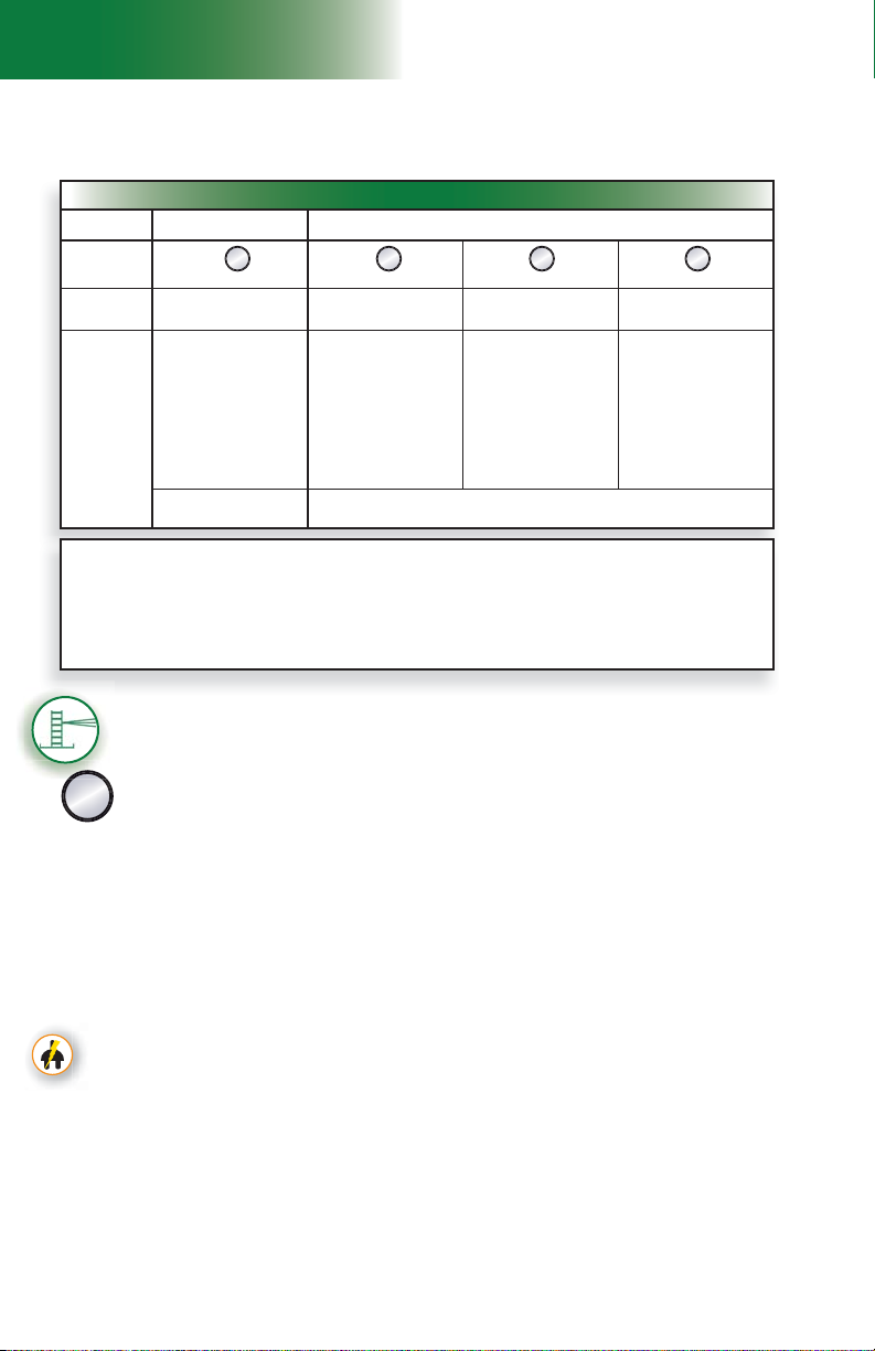
Methods of Installation
Setup and confi gurations
Methods of installation
fi g. 1.30
Methods of Installation
Type of
installation
Method of
installation of
tie levels
Installation
procedure
STANDARD INSTALLATION
ONLY
A B C D
Single unit Single unit Multiple units Multiple units
Progressive installation Pre-installation Pre-installation Pre-installation
1. Installation of unit and all
cantilevers
2. Progressive installation
of tie levels
NOTE: The fi rst two tie levels
must be installed before the start
of any work
LINKED CONFIGURATION
ONLY
1. Installation of units and
two cantilevers
2. Installation of tie levels to
top of work
3. Installation of additional
bridges, equipment and
accessories
STANDARD and NON STANDARD INSTALLATIONS
1. Installation of fi rst
motorized unit with two
cantilevers and complete
tie levels to top of work
2. Installation of second
motorized unit with two
cantilevers and complete
tie levels to top of work
3. Installation of bearing
bridge structure
4. Installation of additional
bridges, equipment and
accessories
INSTALLATION MUST BE CARRIED OUT IN LINKED CONFIGURATION ONLY
Units may be split once all required tie levels are installed to the top of the mast
1. Installation of fi rst
motorized unit without
any bridges
2. Installation of bearing
bridge structure
3. Installation of second
motorized unit without
any bridges
4. Installation of fi rst two
cantilevers
5. Installation of tie levels to
top of the work
6. Installation of additional
bridges, equipment and
accessories
Defi nition of a standard confi guration
A standard confi guration, referred to throughout this owner’s manual and related documentation, is
a linked installation that does not require the use of additional equipment or accessories, such as
a forward extension bridge, a swivel bridge, a planking confi guration wider than three planks, weather
It is mandatory to refer to the Load Capacities section on p. 94 for the number of bridges allowed
protection, a hoist, a monorail or a cantilever reinforcement cable retainer.
in a standard single unit or multiple units installation.
Standard single unit installation with mast ties – progressive installation
The following installation steps can be used for a single unit standard confi guration
only. For more information about the defi nition of a standard confi guration, refer to
A
the box above. This method can be used for a linked confi guration only.
Positioning the motorized unit
1- Prepare the motorized unit and the area where the setup will be installed as described
in the general guidelines starting on p. 17.
2- Lift and align the base of the motorized unit with the face of the work and lower it into position.
3- Using the jacks on the lateral base extensions, level the mast on both its front and
side axis, then, if required, use metal shims to make sure that the base sits squarely
and level on the cribbing.
Connection of the unit and control panel to the power supply (electrical unit)
4- If the unit used in the setup is an electrical unit, select a power cable appropriate for the
height of the mast. Refer to the Power Cable Selection Chart on p. 72 of the Power
Pack and Operating Components section for help with the selection of the power cable.
Make sure that the overall length of the cable is suffi cient for the installation (height of
mast, distance from power source, acceptable overall slack in cable).
5- Install and connect the power cable. This installation must be performed by a certifi ed
electrician. For instructions on the installation of the power cable, refer to the startup
preparation instructions on p. 71 of the Power Pack and Operating Components
section.
Verifi cation of limit switches and screen alerts
6- Pull out the emergency stop button and unlock the display screen. Make sure that the
appropriate confi guration options have been selected (
information about the functions and alerts of the control panel, refer to p. 77 of the
Control Panel section.
F4) on the display screen. For
20
Setup and confi gurations
1 - M U
Standard single unit installation with mast ties – progressive installation
Verifi cation of limit switches and screen alerts (cont’d)
7- Inspect the strobe under the main frame and make sure it is working properly.
8- Review the screen alerts and perform a verifi cation of the limit switches. For instructions
on how to verify the limit switches, refer to p. 48 of the Safety Devices section.
9- If any of the limit switches is not working properly, the unit must be put out of service
until it has been inspected and repaired by a qualifi ed person. For the defi nition of a
qualifi ed person, refer to p. 7 of the Performance and Safety section. For more
information about limit switches and their corresponding alerts, refer to p. 77 of the
Control Panel section.
Installation of bridges
10- With the motorized unit to base level and using bridge installation support brackets or
any other appropriate lifting device such as a crane or a rough terrain forklift, install as
many bridges as is required and allowed. It is important to note that bridge installation
support brackets cannot be used when installing the fi rst bridge attached to the
motorized unit (see p. 110 for more information). For instructions on how to install a
bridge, refer to p. 50 of the Bridges section. Refer to the Load Capacities section
on p. 94 for the maximum number of bridges allowed in a setup.
Installation of mast sections and tie levels
11- Using an optional jib arm, a crane or a rough terrain forklift, load mast sections on
the motorized unit (see p. 119 of the Accessories section for more information on
the installation and use of a jib arm). There can be up to a maximum of four mast
sections on each side of the mast at a time.
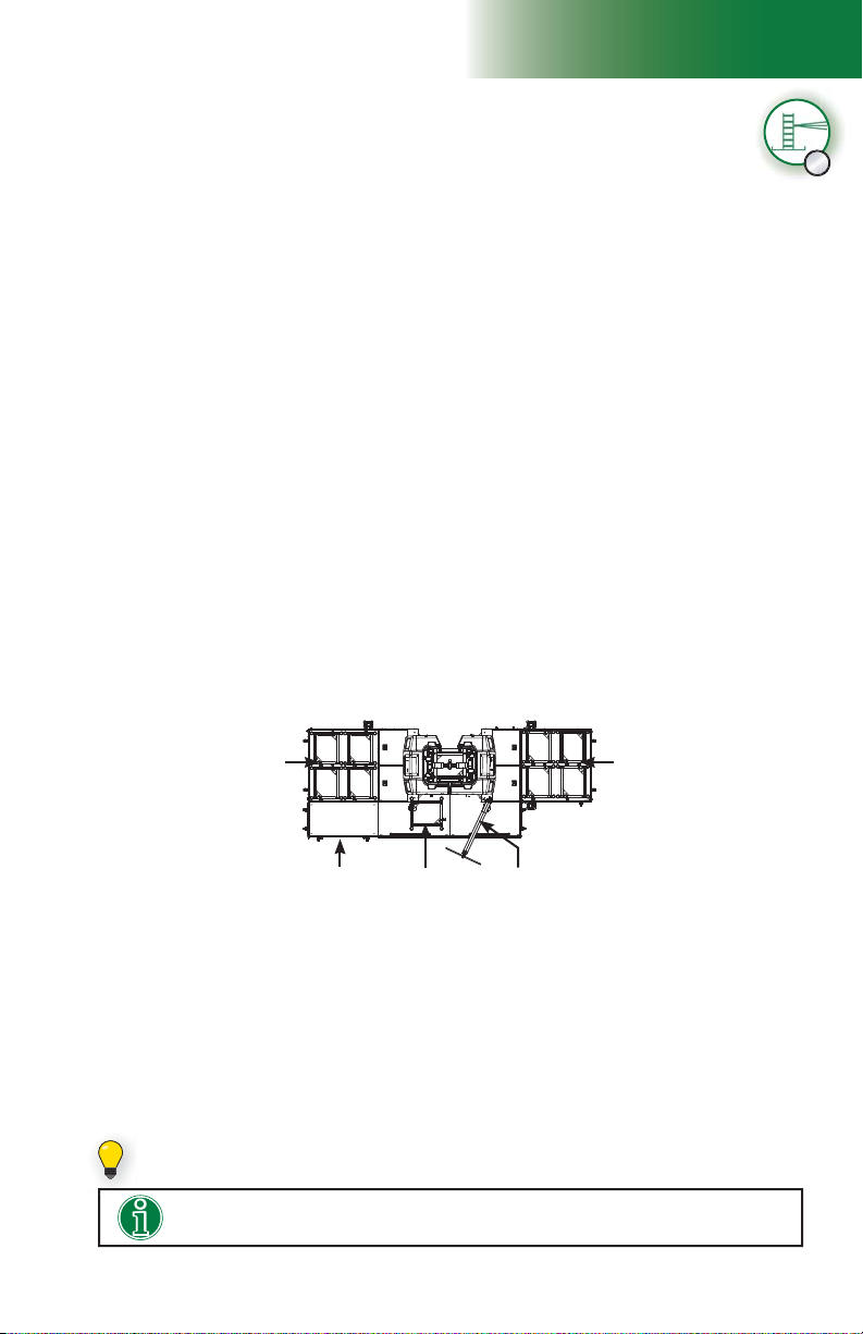
A ninth mast section can be loaded on the link bridge of the motorized unit, as shown
in fi g. 1.31. It is recommended to install an optional deck extension on one of the fi rst
cantilevers attached to the unit to facilitate the handling of mast sections with the jib
arm. The deck extension must be installed on the side opposite to the jib arm, as
shown in fi g. 1.31. For information about the use and installation of an optional deck
extension, refer to p. 55 of the Bridges section.
Four mast sections
on fi rst cantilever
attached to unit
Four mast sections
on fi rst cantilever
attached to unit
A
Optional deck
extension
Mast sections must be loaded equally on either side of the mast and taken alternately
from one side, then the other when installing to ensure good balance. Refer to the
Load Capacities section on p. 94 for more information about loading the platform.
12- Install mast sections until a fi rst tie level is required. For instructions on how to install
mast sections, refer to p. 84 of the Mast and Mast Ties section. Refer to p. 86 of
the Mast and Mast Ties section for instructions on how to install mast ties. For more
information about the schedule of installation of tie levels, refer to the Mast Tie Schedule
tables on p. 87 of the Mast and Mast Ties section.
It is important to note that at least two tie levels must be in place before any work
can be performed from the platform.
Mast section
loaded on the
link bridge
Jib arm
fi g. 1.31
If it is required to load 45' (13,7 m) of mast sections, a ninth mast section can be set
on the link bridge of the motorized unit.
Installing an optional deck extension will facilitate the handling of mast sections
with the jib arm.
21

1 - M U
Setup and Confi gurations
Standard single unit installation with mast ties – progressive installation
A
Installation of mast sections and tie levels (cont’d)
13- Once the fi rst tie level has been installed, proceed with the installation of mast sections
and mast ties, as required. It is important to make sure that at least two tie levels
are in place.
Installation of the mast head
14- Once the installation of mast sections is complete, install the mast head. The mast head
must be put back into place every time the installation of mast sections is complete.
Installing and testing the top limit switch
15- Make sure that the top limit trigger plate on the mast head is in a vertical position. If
necessary, loosen the thumb screws, fl ip the trigger vertically and tighten the thumb
screws by hand.
16- Test the operation of the top limit switch by raising the unit until the switch reaches the
trigger plate. The screen should display an alert for the top limit. If the limit switch is
not working properly, call the distributor/service center. For more information about limit
switches and their corresponding alerts, refer to p. 77 of the Control Panel section.
Greasing of the racks and gears
17- Upon initial setup and subsequently after every 8 to 10 hours of cumulative runtime
(unit travel up and down the mast), grease must be applied to the gears and to the
racks from the top of the mast down. For more information, refer to the daily inspection
checklist for this motorized unit. Grease must be allowed to stand for 2-3 hours before
the motorized unit is used again. Use an open gear lubricant recommended by Hydro
Mobile. Refer to p. 133 of the Transport, Storage and Maintenance section for more
information on the appropriate lubrication method. Lower the motorized unit to base
level, verifying the mast ties and the mast bolts and applying grease, as required, on
the way down. Make sure that all bolt assemblies are tightened to the proper torque
and are in good condition, and that grease is applied appropriately.
Installation of mast guards
18- Once grease has been applied to the gears and the mast racks, install all mast guards.
Installation of outriggers and planking
19- Adjust the outriggers and install planks, as required and allowed (see p. 111 of the
Accessories section for more information).
Verifi cation of the setup
20- Make a fi nal verifi cation of the setup before authorizing workers to use the motorized
unit. Make sure that all the guardrails are in place and secure (see p. 108 of the
Accessories section for more information about guardrails). In all cases where workers
are exposed to fall hazards greater than specifi ed by local regulations, the installation
of guardrails or face guardrail supports is mandatory.
21- Before authorizing workers to use the motorized unit, perform every step in the daily
inspection checklist. It is recommended to fi ll out the handover sheet each time the
setup is modifi ed (addition of mast sections or tie levels, etc.). Refer to p. 134 of
the Transport, Storage and Maintenance section for more information about the daily
inspection checklist and to p. 136 for information about the handover sheet.
22
The mast head must be removed during installation. It is mandatory to put the
mast head back into place before resuming operation of the motorized unit.
The jacks on the base extensions are designed to level the motorized unit and
must not be used to support the load nor the motorized unit.
WARNING
WARNING

Setup and confi gurations
ththeeheeeeee
e
1 - M U
Standard single unit installation with mast ties – progressive installation
Adding mast sections and tie levels progressively
22- Whenever it is necessary to add mast sections and/or tie levels, remove the mast
guards and the mast head. Install as many mast sections and tie levels as is required
and allowed.
23- Put the mast head back into place. Make sure the top trigger plate is positioned properly
and in good condition.
24- Apply grease to the racks of any newly added mast section, from the top of the
new length of mast down. Newly applied grease must be allowed to stand for 2-3
hours before the motorized unit can travel up the mast again. Refer to p. 133 of the
Transport, Storage and Maintenance section for more information on the appropriate
lubrication method.
25- Put the mast guards back in place.
26- Perform a verifi cation of the setup as described in steps 20 and 21.
For safety reasons, it is mandatory to make sure that the operation of the top limit
switch is verifi ed and to make sure that the mast guards and mast head are put
back into place every time mast sections are added to the installation. Grease
must be applied to the racks of the newly added length of mast section.
Single unit installation with mast ties – pre-installation
The following installation steps can be used for standard and non-standard
confi gurations of single unit tied installations. For more information about the
defi nition of a standard confi guration, refer to p. 20 of this section. For more
B
information about the combined use of equipment and accessories in an installation,
refer to the tables for the combinations allowed or restricted in linked and unlinked
confi gurations on p. 17 and p. 18 of this section.
Pre-installation must be performed in a linked configuration only. Once
pre-installation is complete, refer to p. 34 of this section for instructions on how
to split a motorized unit, if required and allowed.
Positioning the motorized unit
1- Prepare the motorized unit and the area where the setup will be installed as described
in the general guidelines starting on p. 17.
2- Lift and align the base of the motorized unit with the face of the work and lower it into position.
3- Using the jacks on the lateral base extensions, level the mast on both its front and
side axis, then, if required, use metal shims to make sure that the base sits squarely
and level on the cribbing.
Connection of the unit and control panel to the power supply (electrical unit)
4- If the unit used in the setup is an electrical unit, select a power cable appropriate for the
height of the mast. Refer to the Power Cable Selection Chart on p. 72 of the Power
Pack and Operating Components section for help with the selection of the power
cable. Make sure that the overall length of the cable is suffi cient for the installation
(height of mast, distance from power source, acceptable overall slack in cable).
5- Install and connect the power cable. This installation must be performed by a certifi ed
electrician. For instructions on the installation of the power cable, refer to the startup
preparation instructions on p. 71 of the Power Pack and Operating Components
section.
A
Installation of the fi rst cantilevers
6- Using any appropriate lifting device such as a crane or a rough terrain forklift, install
only one 5' (1,5 m) bridge on each side of the mast. Refer to the Bridges section
on p. 50 for instructions on bridge installation.
23
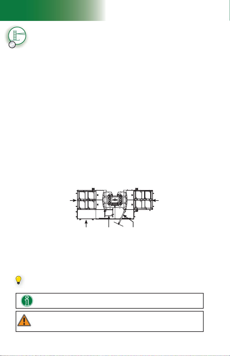
1 - M U
Setup and Confi gurations
B
Verifi cation of limit switches and screen alerts
Single unit installation with mast ties – pre-installation
7- Pull out the emergency stop button and unlock the display screen. Make sure that the
appropriate confi guration options have been selected (
information about the functions and alerts of the control panel, refer to p. 77 of the
Control Panel section.
F4) on the display screen. For
8- Inspect the strobe under the main frame and make sure it is working properly.
9- Review the screen alerts and perform a verifi cation of the limit switches. For instructions
on how to verify the limit switches, refer to p. 48 of the Safety Devices section.
10- If any of the limit switches is not working properly, the unit must be put out of service
until it has been inspected and repaired by a qualifi ed person. For the defi nition of a
qualifi ed person, refer to p. 7 of the Performance and Safety section. For more
information about limit switches and their corresponding alerts, refer to p. 77 of the
Control Panel section.
Installation of mast sections and tie levels
11- Using an optional jib arm, a crane or a rough terrain forklift, load mast sections on
the motorized unit (see p. 119 of the Accessories section for more information on
the installation and use of a jib arm). There can be up to a maximum of four mast
sections on each side of the mast at a time.
A ninth mast section can be loaded on the link bridge of the motorized unit, as shown
in fi g. 1.32. It is recommended to install an optional deck extension on one of the fi rst
cantilevers attached to the unit to facilitate the handling of mast sections with the jib
arm. The deck extension must be installed on the side opposite to the jib arm, as
shown in fi g. 1.32. For information about the use and installation of an optional deck
extension, refer to p. 55 of the Bridges section.
Mast sections must be loaded equally on either side of the mast and taken alternately
from one side, then the other when installing to ensure good balance. Refer to the
Load Capacities section on p. 94 for more information about loading the platform.
Four mast sections
on fi rst cantilever
attached to unit
Four mast sections
on fi rst cantilever
attached to unit
fi g. 1.32
Optional deck
extension
12- Install mast sections until a fi rst tie level is required. For instructions on the installation
of a mast section, refer to p. 84 of the Mast and Mast Ties section. Refer to p. 86
of the Mast and Mast Ties section for instructions on how to install mast ties. For more
information about the schedule of installation of tie levels, refer to the Mast Tie Schedule
tables on p. 87 of the Mast and Mast Ties section. Proceed with the installation of
mast sections until the fi rst two tie levels are in place.
Mast section
loaded on the
link bridge
Jib arm
If it is required to load 45' (13,7 m) of mast sections, a ninth mast section can be set
on the link bridge of the motorized unit.
Installing an optional deck extension will facilitate the handling of mast sections
with the jib arm.
During pre-installation, only mast sections can be loaded on the motorized unit
and the two cantilevers. It is important to note that no other loads are allowed on
the bridges until the pre-installation process is complete.
WARNING
24

Setup and confi gurations
1 - M U
Single unit installation with mast ties – pre-installation
Installation of mast sections and tie levels (cont’d)
13- Once the fi rst tie level has been installed, proceed with the i
mast sections and tie levels as is required by the layout plan and the confi guration.
14- Proceed with the installation of as many mast sections and tie levels as is required by
the layout plan and the confi guration. Any F2 Series motorized unit must not be used
on a mast with a height over 500' (152 m).
nstallation of as many
Installation of the mast head
15- Once the installation of mast sections and tie levels is complete, install the mast head.
Installing and testing the top limit switch
16- Make sure that the top limit trigger plate on the mast head is in a vertical position. If
necessary, loosen the thumb screws, fl ip the trigger vertically and tighten the thumb
screws by hand.
17- Test the operation of the top limit switch by raising the unit until the switch reaches the
trigger plate. The screen should display an alert for the top limit. If the limit switch is not
working properly, call the distributor/service center. For more information about limit
switches and their corresponding alerts, refer to p. 77 of the Control Panel section.
Greasing of the racks and gears
18- Upon initial setup and subsequently after every 8 to 10 hours of cumulative runtime
(unit travel up and down the mast), grease must be applied to the gears and to the
racks, from the top of the mast down. For more information, refer to the daily inspection
checklist for this motorized unit. Grease must be allowed to stand for 2-3 hours before
the motorized unit is used again. Use an open gear lubricant recommended by Hydro
Mobile. Refer to p. 133 of the Transport, Storage and Maintenance section for more
information on the appropriate lubrication method. Lower the motorized unit to base
level, verifying the mast ties and the mast bolts and applying grease, as required, on
the way down. Make sure that all bolt assemblies are tightened to the proper torque
and are in good condition, and that grease is applied appropriately.
Installation of the mast guards
19- Once grease has been applied to the gears and the mast racks, install all mast guards.
Installation of additional bridges, equipment and accessories
20- With the unit at base level, install as many additional bridges as is required and allowed.
Refer to the Load Capacities section on p. 94 for the maximum number of bridges
allowed in a setup.
21- Install additional equipment and accessories as is required and allowed. For more
information about the combined use of equipment and accessories in an installation,
refer to the tables for the combinations allowed or restricted in linked and unlinked
confi gurations on p. 17 and p. 18 of this section. For instructions on the installation
and use of an extension bridge or a swivel bridge, refer to the Bridges section on p. 50.
For instructions on the installation and use of any other accessory such as a monorail
or weather protection, refer to the Accessories section on p. 123.
Installation of outriggers and planking
22- Adjust the outriggers and install planks, as required and allowed (see p. 111 of the
Accessories section for more information).
Verifi cation of the setup
23- Make a fi nal verifi cation of the setup before authorizing workers to use the motorized
unit. Make sure that all the guardrails are in place and secure (see p. 108 of the
Accessories section for more information about guardrails). In all cases where workers
are exposed to fall hazards greater than specifi ed by local regulations, the installation
of guardrails or face guardrail supports is mandatory.
24- Before authorizing workers to use the motorized unit, perform every step in the daily
inspection checklist. It is recommended to fi ll out the handover sheet to complete the
installation. Refer to p. 134 of the Transport, Storage and Maintenance section for
more information about the daily inspection checklist and to p. 136 for information
about the handover sheet.
B
25
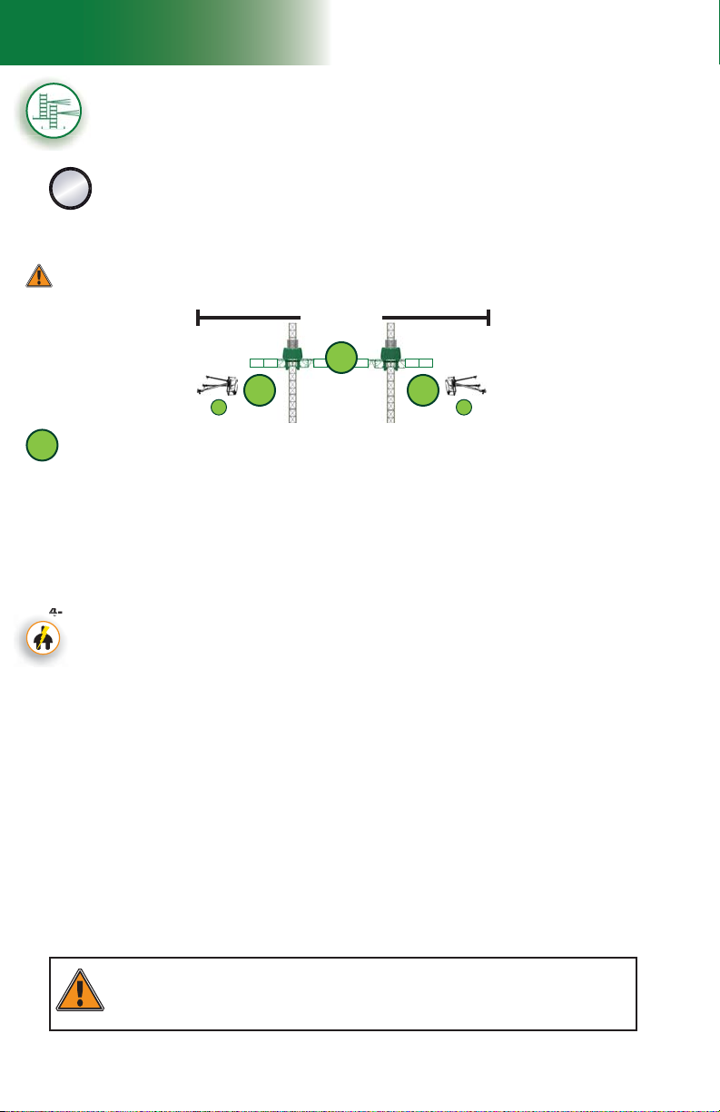
1 - M U
444444444
Setup and Confi gurations
Multiple units installation with mast ties – pre-installation
(requires two twin mast adapters – sold separately)
The following installation steps can be used for standard and non-standard
confi gurations of tied installations with multiple units linked by a bearing
bridge. For more information about the defi nition of a standard confi guration, refer to
C
p. 20 of this section. For more information about the combined use of equipment
and accessories in an installation, refer to the tables for the combinations allowed or
restricted in linked and unlinked confi gurations on p. 17 and p. 18 of this section.
Pre-installation must be performed in a linked confi guration only. Once pre-installation is
complete, refer to p. 34 of this section for instructions on how to split a motorized
unit, if required and allowed.
Top of work
3
fi g. 1.33
1
Positioning the fi rst motorized unit
1- Prepare the fi rst motorized unit and the area where the setup will be installed as
described in the general guidelines starting on p. 17.
2- Lift and align the base of the motorized unit with the face of the work and lower it into position.
3- Using the jacks on the lateral base extensions, level the mast on both its front and
side axis, then, if required, use metal shims to make sure that the base sits squarely
and level on the cribbing.
Connection of the unit and control panel to the power supply (electrical unit)
4- If the unit used in the setup is an electrical unit, select a power cable appropriate for the
height of the mast. Refer to the Power Cable Selection Chart on p. 72 of the Power
Pack and Operating Components section for help with the selection of the power cable.
Make sure that the overall length of the cable is suffi cient for the installation (height of
mast, distance from power source, acceptable overall slack in cable).
5- Install and connect the power cable. This installation must be performed by a
certifi ed electrician. For instructions on the installation of the power cable, refer
to the startup preparation instructions on p. 71 of the Power Pack and Operating
Components section.
Installation of the fi rst cantilevers
6- Using any appropriate lifting device such as a crane or a rough terrain forklift, install
only one 5' (1,5 m) bridge on each side of the mast. Refer to the Bridges section
on p. 50 for instructions on bridge installation.
Verifi cation of limit switches and screen alerts
7- Pull out the emergency stop button and unlock the display screen. Make sure that the
appropriate confi guration options have been selected (
information about the functions and alerts of the control panel, refer to p. 77 of the
Control Panel section.
8- Inspect the strobe under the main frame and make sure it is working properly.
9- Review the screen alerts and perform a verifi cation of the limit switches. For instructions
on how to verify the limit switches, refer to p. 48 of the Safety Devices section.
1 2
Installation of the fi rst motorized unit
21
F4) on the display screen. For
It is recommended that two persons handle all rise and descent operations of each motorized
unit and that at least one of those two persons is a qualifi ed operator. It is important to
coordinate the motion of motorized units linked by a bearing bridge to keep the structure as level
26
WARNING
as possible.
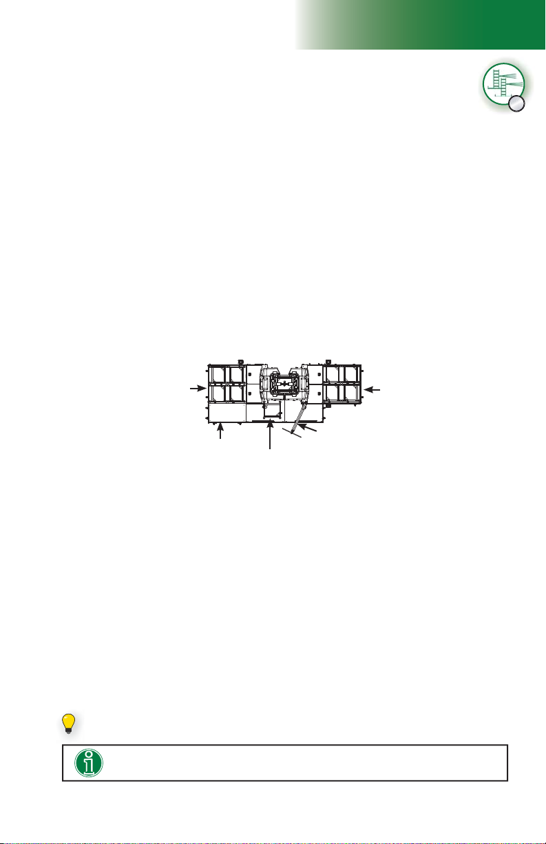
1 - M U
Setup and Confi gurations
Multiple units installation with mast ties – pre-installation
(requires two twin mast adapters – sold separately)
Verifi cation of limit switches and screen alerts (cont’d)
10- If any of the limit switches is not working properly, the unit must be put out of service
until it has been inspected and repaired by a qualifi ed person. For the defi nition of a
qualifi ed person, refer to p. 7 of the Performance and Safety section. For more
information about limit switches and their corresponding alerts, refer to p. 77 of the
Control Panel section.
Installation of mast sections and tie levels
11- Using an optional jib arm, a crane or a rough terrain forklift, load mast sections on
the motorized unit (see p. 119 of the Accessories section for more information on
the installation and use of a jib arm). There can be up to a maximum of four mast
sections on each side of the mast at a time.
A ninth mast section can be loaded on the link bridge of the motorized unit, as shown
in fi g. 1.32. It is recommended to install an optional deck extension on one of the fi rst
cantilevers attached to the unit to facilitate the handling of mast sections with the jib
arm. The deck extension must be installed on the side opposite to the jib arm, as
shown in fi g. 1.32. For information about the use and installation of an optional deck
extension, refer to p. 55 of the Bridges section.
Mast sections must be loaded equally on either side of the mast and taken alternately
from one side, then the other when installing to ensure good balance. Refer to the
Load Capacities section on p. 94 for more information about loading the platform.
C
Four mast sections
on fi rst cantilever
attached to unit
Optional deck
extension
12- Install mast sections until a fi rst tie level is required. For instructions on the installation
of a mast section, refer to p. 84 of the Mast and Mast Ties section. Refer to p. 86
of the Mast and Mast Ties section for instructions on how to install mast ties. For more
information about the schedule of installation of tie levels, refer to the Mast Tie Schedule
tables on p. 87 of the Mast and Mast Ties section.
Once the fi rst tie level has been installed, proceed with the installation of as many mast
sections and tie levels as is required by the layout plan and the confi guration. Any F2
Series motorized unit must not be used on a mast with a height over 500' (152 m).
Mast section loaded on
the link bridge
Jib arm
Four mast sections
on fi rst cantilever
attached to unit
fi g. 1.34
Installation of the mast head
13- Once all required mast sections and tie levels are in place, install the mast head.
Installing and testing the top limit switch
14- Make sure that the top limit trigger plate on the mast head is in a vertical position. If
necessary, loosen the thumb screws, fl ip the trigger vertically and tighten the thumb
screws by hand.
15- Test the operation of the top limit switch by raising the unit until the switch reaches the
trigger plate. The screen should display an alert for the top limit. If the limit switch is
not working properly, call the distributor/service center. For more information about limit
switches and their corresponding alerts, refer to p. 77 of the Control Panel section.
If it is required to load 45' (13,7 m) of mast sections, a ninth mast section can be set
on the link bridge of the motorized unit.
Installing an optional deck extension will facilitate the handling of mast sections
with the jib arm.
27
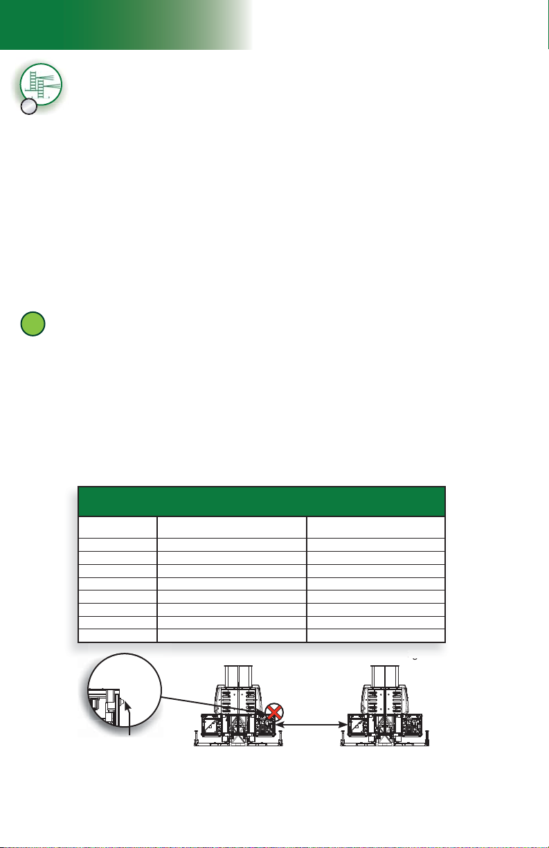
1 - M U
Distances for a bearing installation
(approximate distances)
Setup and Confi gurations
Multiple units installation with mast ties – pre-installation
C
(requires two twin mast adapters – sold separately)
Greasing of the racks and gears
16- Upon initial setup and subsequently after every 8 to 10 hours of cumulative runtime (unit
travel up and down the mast), grease must be applied to the gears and to the racks, from
the top of the mast down. For more information, refer to the daily inspection checklist for
this motorized unit. Grease must be allowed to stand for 2-3 hours before the motorized
unit is used again. Use an open gear lubricant recommended by Hydro Mobile. Refer
to p. 133 of the Transport, Storage and Maintenance section for more information on
the appropriate lubrication method. Lower the motorized unit to base level, verifying
the mast ties and the mast bolts and applying grease, as required, on the way down.
Make sure that all bolt assemblies are tightened to the proper torque and are in good
condition, and that grease is applied appropriately.
Installation of the mast guards
17- Once grease has been applied to the gears and the mast racks, install all mast guards.
Remove and store the jib arm, if necessary.
2
Installation of the second motorized unit
Positioning and installing the second motorized unit
1- Determine the position of the second motorized unit according to the length of the
bearing bridge to be installed.
2- To determine the length of the bearing bridge, use the Distances for a bearing
installation table in fi g. 1.35 as a guide or assemble the bearing bridge and measure the
overall length of the structure, including the twin mast adapters at each end of the structure.
If required, refer to the safety guidelines and to steps 1 through 4 of the instructions for
the assembly of a bearing bridge structure on p. 52 of the Bridges section.
3- Install the second motorized unit following steps 1 through 18 of the installation
instructions for the fi rst motorized unit, starting on p. 26.
Distances for a bearing installation
(approximate distances)
No. of bridges
10 65' (19,8 m) 55' (16,8 m)
9 60' (18,3 m) 50' (15,2 m)
8 55' (16,8 m) 45' (13,7 m)
7 50' (15,2 m) 40' (12,2 m)
6 45' (13,7 m) 35' (10,7 m)
5 40' (12,2 m) 30' (9,1 m)
4 35' (10,7 m) 25' (7,6 m)
3 30' (9,2 m) 20' (6,1 m)
fi g. 1.37
Bushing on main
frame of unit
It’s important to make sure that the distance between the two motorized units is measured from
frame to frame and not from bushing to bushing (fi g. 1.37).
Distances from
center to center of masts
Distances between main frames
Distance
measured from
frame to frame
fi g. 1.35
fi g. 1.36
28

Setup and Confi gurations
1 - M U
Multiple units installation with mast ties – pre-installation
(requires two twin mast adapters – sold separately)
Completing the multiple units installation
Installation of the bearing bridge structure
1- Make sure the bearing bridge structure has been assembled as described in the
assembly instructions on p. 52 of the Bridges section.
2- Make sure that the twin mast adapters are installed at each end of the bearing bridge
structure. For instructions on the installation of a twin mast adapter, refer to p. 52 of
the Bridges section. It is important to make sure that the locking plates on the twin mast
adapters remain in place until the installation of the bearing bridge structure is complete.
3- Proceed with the installation of the bearing bridge structure following the installation
instructions on p. 53 of the Bridges section. Once the installation of the structure is
complete, make sure the lock plates have been unhooked on each twin mast adapter.
Installation of additional bridges, equipment and accessories
4- With the unit at base level, install as many additional cantilevers as is required and
allowed. Refer to the Load Capacities section on p. 94 for the maximum number of
bridges allowed in a setup.
5- Install additional equipment and accessories as is required and allowed. For more
information about the combined use of equipment and accessories in an installation,
refer to the tables for the combinations allowed or restricted in linked and unlinked
confi gurations on p. 17 and p. 18 of this section. For instructions on the installation
and use of an extension bridge or a swivel bridge, refer to the Bridges section on p. 50.
For instructions on the installation and use of any other accessory such as a monorail
or weather protection, refer to the Accessories section on p. 123.
Installation of outriggers and planking
6- Adjust the outriggers and install planks, as required and allowed (see p. 111 of the
Accessories section for more information).
Verifi cation of the setup
7- Make a fi nal verifi cation of the setup before authorizing workers to use the motorized
unit. Make sure that all the guardrails are in place and secure (see p. 108 of the
Accessories section for more information about guardrails). In all cases where workers
are exposed to fall hazards greater than specifi ed by local regulations, the installation
of guardrails or face guardrail supports is mandatory.
8- Before authorizing workers to use the motorized unit, perform every step in the daily
inspection checklist. It is recommended to fi ll out the handover sheet to complete the
installation. Refer to p. 134 of the Transport, Storage and Maintenance section for
more information about the daily inspection checklist and to p. 136 for information
about the handover sheet.
C
3
WARNING
When weather protection is required and allowed, tarps and shields must only be
installed once all tie levels are in place up to the top of the work.
WARNING
It is important to make sure to plug in all inclinometers and to enable the
inclinometer option on each display screen of the bearing bridge installation. It is
also essential to perform the 0-degree level adjustment for each inclinometer.
WARNING
It is recommended that two persons handle all rise and descent operations of
each motorized unit and that at least one of those two persons is a qualifi ed
operator. It is important to coordinate the motion of motorized units linked by a
bearing bridge to keep the structure as level as possible.
29
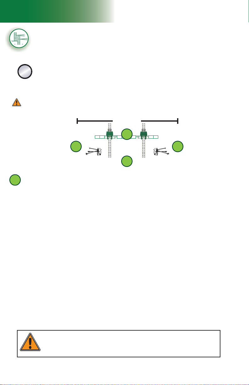
1 - M U
Setup and Confi gurations
Multiple units installation with mast ties – pre-installation
(requires two twin mast adapters – sold separately)
The following installation steps can be used for standard and non-standard
confi gurations of tied installations with multiple units linked by a bearing
bridge. For more information about the defi nition of a standard confi guration, refer to
D
p. 20 of this section. For more information about the combined use of equipment
and accessories in an installation, refer to the tables for the combinations allowed or
restricted in linked and unlinked confi gurations on p. 17 and p. 18 of this section.
Pre-installation must be performed in a linked confi guration only. Once pre-installation is
complete, refer to p. 34 of this section for instructions on how to split a motorized
unit, if required and allowed.
Top of work
1
1
fi g. 1.38
1
2
1
Positioning the fi rst motorized unit
1- Prepare the fi rst motorized unit and the area where the setup will be installed as
described in the general guidelines starting on p. 17.
2- Lift and align the base of the motorized unit with the face of the work and lower it into position.
3- Using the jacks on the lateral base extensions, level the mast on both its front and
side axis, then, if required, use metal shims to make sure that the base sits squarely
and level on the cribbing.
Installation of the bearing bridge structure
4- Make sure the bearing bridge structure has been assembled as described in the
assembly instructions on p. 52 of the Bridges.
5- Make sure that a twin mast adapter is installed at the end of the bearing bridge structure
to be attached to the fi rst motorized unit. For instructions on the installation of a twin
mast adapter, refer to p. 52 of the Bridges section. It is important to make sure that
the locking plates on the twin mast adapter remain in place until the installation of the
bearing bridge structure is complete.
6- Using a rough terrain forklift, a crane or any other appropriate lifting device, lift the
bearing structure, align it with the motorized unit installed and lower it into position.
7- Still holding the bearing bridge structure, bolt the twin mast adapter to the main frame
of the fi rst motorized unit. Make sure that the end of the bearing bridge that is not yet
bolted to a unit is supported.
Positioning the second motorized unit
8- Prepare the second motorized unit and the area where the setup will be installed as
described in the general guidelines on p. 17.
Installation of units and bridges
30
It is important to make sure to plug in all inclinometers and to enable the
WARNING
inclinometer option on each screen of the bearing bridge installation. It is
also essential to perform the 0-degree level adjustment for each inclinometer.

Setup and Confi gurations
1 - M U
Multiple units installation with mast ties – pre-installation
(requires two twin mast adapters – sold separately)
Positioning the second motorized unit (cont’d)
9- Align the motorized unit with the end of the bearing bridge structure lower it into position,
making sure the base is properly aligned with the face of the work.
10- Using the jacks on the lateral base extensions, level the mast on both its front and
side axis, then, if required, use metal shims to make sure that the base sits squarely
and level on the cribbing.
Completing the installation of the bearing bridge
11- Bolt the twin mast adapter at the end of the bearing bridge structure to the main frame
of the second motorized unit. It is important to make sure that the locking plates on the
twin mast adapter remain in place until the installation of the bearing bridge structure
is complete.
12- Complete the installation of the bearing bridge structure as described in steps 3 through
6 of the installation instructions on p. 53 of the Bridges section.
Installation of the fi rst cantilevers
13- Using any appropriate lifting device such as a crane or a rough terrain forklift, install
only one 5' (1,5 m) bridge at the cantilever end of each motorized unit.
Connection of the units and control panels to the power supply (electrical unit)
14- If the units used in the setup are electrical units, select the appropriate power cables
for the height of the masts. Refer to the Power Cable Selection Chart on p. 72 of the
Power Pack and Operating Components section for help with the selection of the power
cables. Make sure that the overall length of each cable is suffi cient for the installation
(height of setup, distance from power source, acceptable overall slack in cable).
15- Install and connect the power cables. This installation must be performed by a
certifi ed electrician. For instructions on the installation of a power cable, refer to
the startup preparation instructions on p. 71 of the Power Pack and Operating
Components section.
Verifi cation of limit switches and screen alerts (on each motorized unit)
16- Pull out the emergency stop button and unlock the display screen. Make sure that the
appropriate confi guration options have been selected (
information about the functions and alerts of the control panel, refer to p. 77 of the
Control Panel section.
F4) in the control panel. For
17- Inspect the strobe under the main frame and make sure it is working properly.
18- Review the screen alerts and perform a verifi cation of the limit switches. For instructions
on how to verify the limit switches, refer to p. 48 of the Safety Devices section.
19- If any of the limit switches is not working properly, the unit must be put out of service
until it has been inspected and repaired by a qualifi ed person. For the defi nition of a
qualifi ed person, refer to p. 7 of the Performance and Safety section. For more
information about limit switches and their corresponding alerts, refer to p. 77 of the
Control Panel section.
D
It is important to verify limit switches and screen alerts on both motorized units as
It is recommended that two persons handle all rise and descent operations of each
motorized unit and that at least one of those two persons is a qualifi ed operator.
It is important to coordinate the motion of motorized units linked by a bearing
simultaneously as possible.
bridge to keep the structure as level as possible.
WARNING
WARNING
31
 Loading...