

Page 1

965520 Rev. E
5/02
Package Contains:
1. Proportioner with U-clamp for mounting
2. Float with chain
3. Suction tube with foot valve -- 9 ft.
4. Discharge tube -- 2 ft.
5. Metering tip kit (14 tips)
6. Production information sheet
HydroMinder Model 511
protective clothing and eyewear when dispensing chemicals or other materials.
observe safety and handling instructions of the chemical manufacturers.
direct discharge away from you or other persons or into approved containers.
dispense cleaners and chemicals in accordance with manufacturer's instructions. Exercise
CAUTION when maintaining your equipment.
equipment clean for proper operation.
protective clothing and eyewear when working in the vicinity of all chemicals, filling or emptying
equipment or changing metering tips.
re-assemble equipment according to instruction procedures. Be sure all components are firmly
screwed or latched into position.
only to tap water outlets (85 PSI maximum).
WEAR
THANK YOU FOR YOUR INTEREST IN OUR PRODUCTS
Hydro Systems manufactures quality chemical proportioners. Please use this equipment carefully and observe all
warnings and cautions.
****************************************************************NOTE ************************************************************
ALWAYS
ALWAYS
ALWAYS
KEEP
WEAR
ALWAYS
ATTACH
Through proper care and maintenance, this equipment will serve your toughest cleaning jobs.
Installation:
1. Mount the unit in a level position on the side of a reservoir. The U-clamp may be repositioned or removed as necessary.
2. Install a minimum ½" ID water hose between the inlet threads and the water spigot. Minimum water pressure required
to properly operate the proportioner is 25 PSI (flowing).
3. Attach the end of the discharge tube with the clamp and flooding ring to the discharge barb on the eductor.
4. Insert the foot valve end of the suction tube into the concentrate container. (The level of the concentrate must be below
the level of the eductor, or the proportioner will continue to siphon concentrate after it is turned "off".)
5. Select a metering tip (see next two sections) and screw it into the suction stub on the eductor body.
6. Slide the open end of the suction tube over the suction stub.
7. Adjust the bead chain length to position the float at the desired level of solution. To prevent foaming, be certain that the
solution level will always be above the point of discharge. Be sure floa
t mechanism is not hampered by water turbulence
caused by discharging solution. It may be necessary to baffle the float from the discharge in order for the unit to work
properly.
Metering Tip Selection:
The final concentration of the dispensed liquid is related to both the size of the metering tip opening (orifice) and the viscosity
of the liquid being siphoned. If product viscosity is noticeably greater than that of water, consult the procedure for
Measurement of Concentration on the next page to achieve your desired water-to-product ratio. For water-thin products,
use the chart below as a guideline. Because such factors as inlet water pressure and temperature can affect dilution ratios,
the figures listed below are only approximate. Test the actual dilution you are achieving using the Measurement of
Concentration procedure for best results. Two undrilled, clear tips are supplied for drilling sizes not listed.
Approx. Ratio @ 40 PSI,
Tip Color Drill Size water-thin viscosity
No tip 4:1
Gray 30 5:1
Black 40 6:1
Beige 50 8:1
Red 55 17:1
White 57 23:1
Blue 60 25:1
Tan 65 36:1
Green 70 48:1
Orange 72 64:1
Brown 74 75:1
Yellow 76 90:1
Purple 80 120:1
Pink 87 240:1
Approx. Ratio @ 40 PSI,
Tip Color Drill Size water-thin viscosity
Page 2
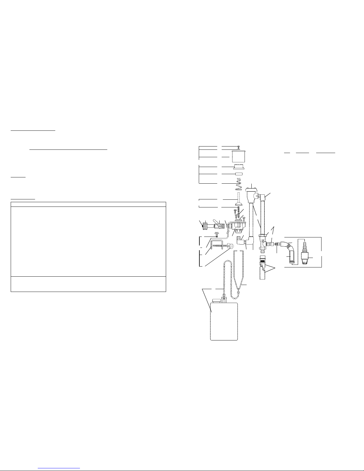
HydroMinder Model 511 Parts Diagram/List
1 2 3 4
i
h
k
m
6
n
p
q
r
9
13
18
x
KEY PART NO. DESCRIPTION
1 238100 strainer washer
2 506500 hose swivel
3 502000 ball valve
4 360900 nipple
5 10080500 magnet parts kit
a. screw
b. washer
c. magnet cover
d. magnet cap
e. magnet
f. magnet spring
g. magnet yoke
6 5030-K mounting bracket kit
(specify model 511)
h. Z bracket
i. U clamp
j. lockwasher (not shown)
k. screw
m.thumbscrew
7 665520 valve parts kit
n. valve guide ("bonnet")
p. armature spring
q. armature
r. diaphram
8 520000 water valve body
9 505600 street elbow
10 519000 close nipple, 1/4"
11 506000 elbow
12 505900 nipple, 6"
13 506300 vacuum breaker
14 440121 eductor assembly
440100 s. eductor body only
440101 t. suction stub only
15 690015 metering tip (kit)
16 5057-A discharge tube assembly
17 5058-9A suction tube assembly
505809 u. tubing, 1/2" x 9'
250006 v. ceramic weight
10076301 w.foot valve, Viton
250700 (foot valve & weight)
18 5043-A float & chain assembly
507200 x. bead chain only
5g
8
9
10
11
12
14
s
t
u
17
15
v
w
16
5
a
b
c
d
e
f
7
Measurement of Concentration:
You can determine the dispensed water-to-product ratio for any metering tip size and product viscosity. All that is required
is to operate the primed dispenser for a minute or so and note two things: the amount of dispensed water/product mixture,
and the amount of concentrate used in preparation of the solution dispensed. The water-to-product ratio is then calculated
as follows:
Dilution (X) = Amount of Mixed Solution — Amount of Concentrate Drawn
Amount of Concentrate Drawn
Dilution ratio, then, equals X parts water to one part concentrate (X:1). If the test does not yield the desired ratio, choose
a different tip and repeat the test.
Alternative methods to this test are 1) pH (using litmus paper), and 2) titration. Contact your concentrate supplier for further
information on these alternative methods and the materials required to perform them.
Operation:
Open the water supply ball valve. When the solution in the reservoir reaches the level set by the float, the valve will close.
This will stop the water flow and siphoning of concentrate. When withdrawal of solution from the reservoir causes the level
to drop more than 1-1/2 inches, the valve will open, and the reservoir will be refilled to the previous, pre-set level. This cycle
will be repeated automatically until the supply of concentrate is depleted. The ball valve should be fully closed when
changing metering tips or concentrate container, when reservoir is drained, or when the unit is not in use.
Troubleshooting:
Problem Probable Cause Remedy
1. No discharge a. No water a. Open water inlet
b. Defective magnetic b. Replace assembly
valve assembly
c. Excessive water pressure c. Install regulator if pressure exceeds 85 PSI
2. No concentrate a. Clogged foot valve a. Clean or replace foot valve
draw b. Metering tip or eductor b. Clean* or replace
clogged
c. Low water pressure c. Minimum 25 PSI flowing required
d. Discharge tube or d. Check position: Replace discharge tube if
flooding ring not in place flooding ring is missing.
3. Failure of unit to a. Valve parts dirty or a. Clean or replace
turn off defective
b. Magnet spring too short b. Replace
c. Clogged valve orifice c. Clean or replace
4. Backflow into a. Diluted solution being a. Replace or repair foot valve
concentrate siphoned into container
b. Water being siphoned b. Replace eductor
into container
* In hard water areas, scale may form at the discharge of the eductor. This scale may be removed by
soaking the eductor in a descaling solution or by running the descaling solution through the system. If
descaling solution is educted through the system, flush the unit by educting water only before returning
the system to regular use.
 Loading...