

Page 1

Hydrological Services Pty Ltd
WIRELESS LEVEL TRANSMITTER
MODEL WLT420
OPERATING MANUAL
HYDROLOGICAL SERVICES Pty Ltd
48-50 Scrivener Street
Liverpool NSW 2170
Australia
Ph. 61 2 9601 2022 Fax. 61 2 9602 6971
E-Mail: [email protected]
1
Page 2

Hydrological Services Pty Ltd
TABLE OF CONTENTS
Product Overview ...................................................................................... 3
1.
2. Installation ................................................................................................. 4
2.1 Hardware Connections ....................................................................................... 4
2.2 Antenna Mounting............................................................................................... 7
2.3 Power Supply....................................................................................................... 7
3. Operation ................................................................................................... 8
3.1 Transmitter LED.................................................................................................8
3.2 LCD Navigation...................................................................................................8
3.3 Displaying Water Volume................................................................................... 10
4. Specification...............................................................................................11
4.1 Hardware Specification....................................................................................... 11
Appendix A Connecting a WL1200W Transducer ...................................... 12
Appendix B Creating the Level to Volume Formula.................................... 13
Wireless Level Transmitter
© Copyright
WLT420 100-2 Issue 1.20 5 Dec, 2007
Page 3
Hydrological Services Pty Ltd
1. Product Overview
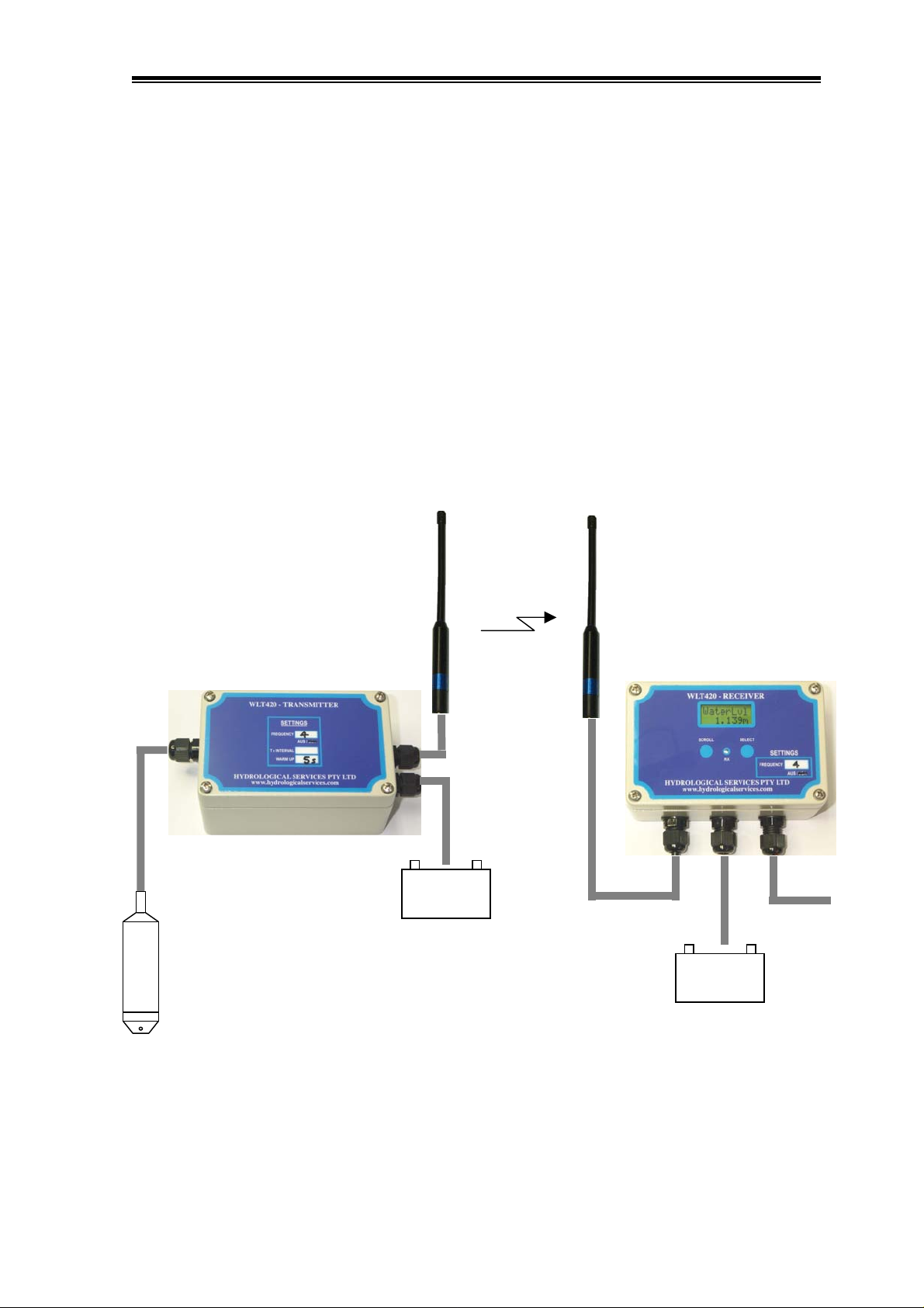
The Hydrological Services Wireless Level Transmitter WLT420 has been designed using
surface mount technology to provide a very small, ultra low power and reliable wireless 4 to
20mA transmitter / receiver pair that can be used in harsh environments for extended periods.
The Wireless Level Transmitter’s primary purpose is to periodically measure a 4-20mA
transducer, and to wirelessly transmit the measurement to a different location and reproduce
the 4-20mA signal. This is done with a very low power consumption (typically 150uA while
asleep) which makes it ideal for remote sites where long battery life is important. The
receiver also has an LCD to display the water level, current measurement and other
parameters.
Wireless Level
Transmitter
1km range
Wireless Level
Receiver
Wireless Level Transmitter
© Copyright
4-20mA Pressure
Transducer
+-
4-20mA
12V Battery
+ -
12V Battery
output
WLT420 100-3 Issue 1.20 5 Dec, 2007
Page 4
Hydrological Services Pty Ltd
2. Installation
2.1 Hardware Connections
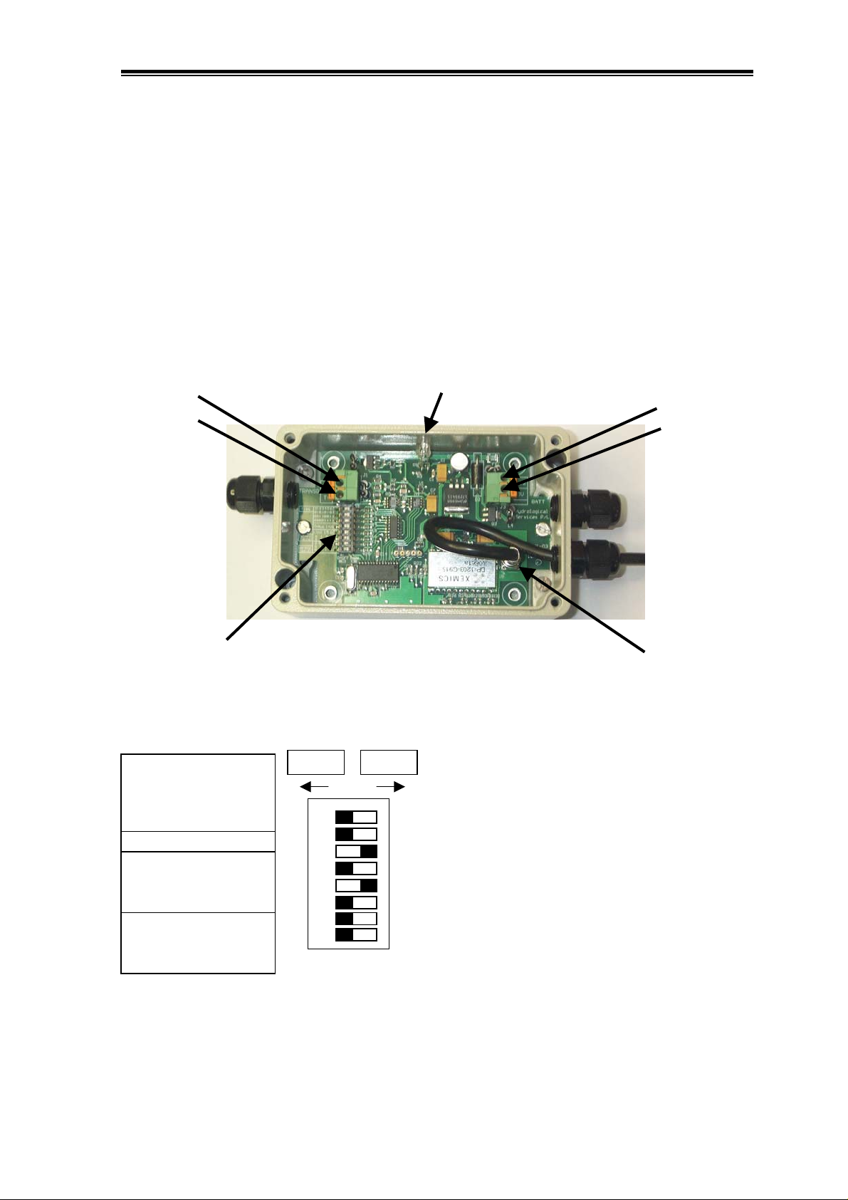
The Wireless Level Transmitter periodically switches the battery voltage to the transducer for
the warm up time (preset on the DIP switches) and then measures the 4-20mA current.
The terminals are screwless, simply push the wire into terminal hole – you may need to
depress the orange release lever if fine wire is used. This lever is also used to remove the
wire.
Status LED
Transducer +
Transducer -
Battery +
Battery -
Configuration
DIP Switches
Freq 0 1 2 3 4 5 6 7
1: 0 1 0 1 0 1 0 1
2: 0 0 1 1 0 0 1 1
3: 0 0 0 0 1 1 1 1
=
TxInt cnt 1 15 60
5: 0 1 0 1
6: 0 0 1 1
WarmUp 2 5 10 15
7: 0 1 0 1
8: 0 0 1 1
=
Wireless Level
Transmitter
DIP Switches 1,2,3 set the transmission frequency
=
1
2
3
4
5
6
7
8
=
and DIP switch 4 sets the frequency band for :
USA and Australia.
0 = 905.5MHz 917.5MHz
1 = 906.5MHz 918.5MHz
2 = 907.5MHz 919.5MHz
3 = 908.5MHz 920.5MHz
4 = 909.5MHz 921.5MHz
5 = 910.8MHz 922.5MHz
6 = 911.9MHz 923.5MHz
7 = 912.5MHz 924.5MHz
DIP Switches 5 and 6 set the transmission interval (in
minutes) to continuous, 1 min, 15 min and 60 min.
DIP Switches 7 and 8 set the transducer warm up (in
seconds) to 2 secs, 5 secs, 10 secs and 15 secs.
Aerial
Wireless Level Transmitter
© Copyright
WLT420 100-4 Issue 1.20 5 Dec, 2007
Page 5
Hydrological Services Pty Ltd
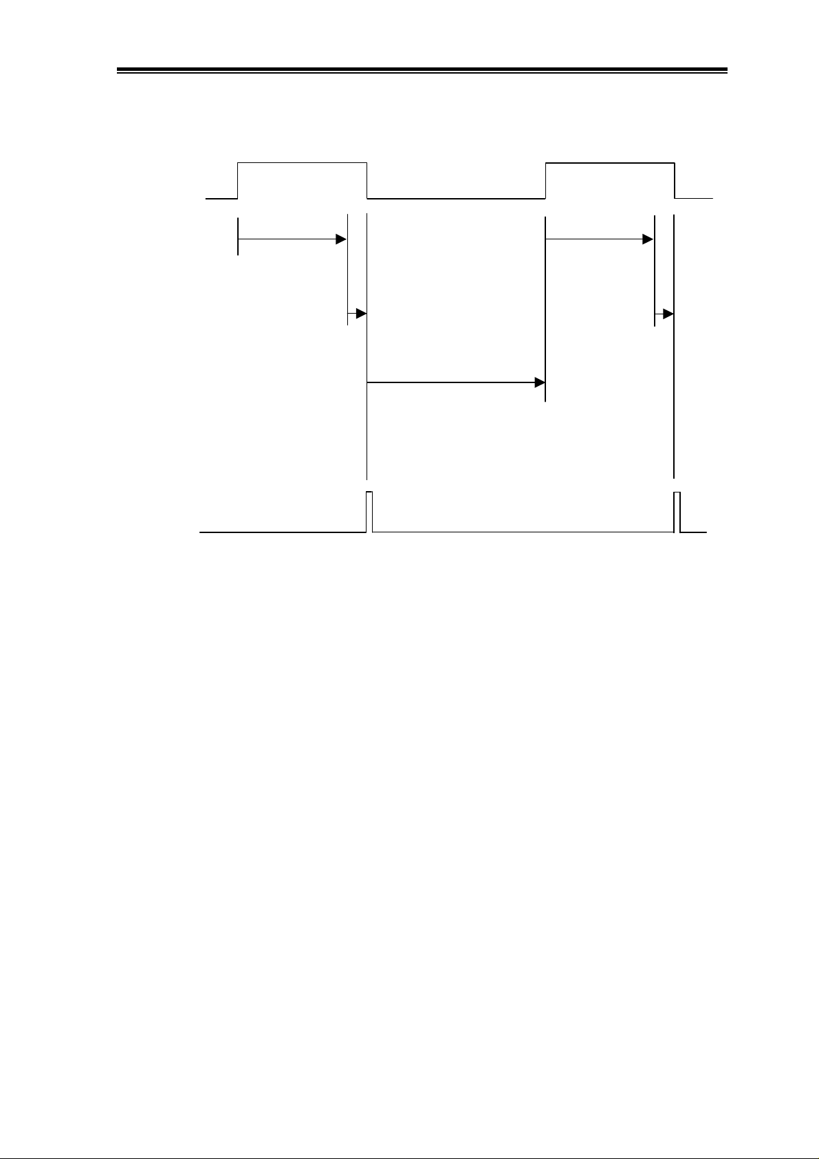
Transducer
Transmission
Power
On
Warm Up
2,5,10,15 Secs
Sample
1 Sec
Transmission Interval
(continuous = 0 mins)
Off
TxInt
0,1,15,60 Mins
On
Warm Up
2,5,10,15 Secs
Sample
1 Sec
What are the WarmUp and TxInt periods ?
The transducer is powered on during the Warm Up period and then a sample is taken lasting 1
second. (256 x 12 bit samples are taken during this 1 second period and averaged) Power is
removed from the transducer, the data is transmitted and the LED flashed. The Wireless
Level Transmitter then goes to sleep during the Transmission Interval to conserve the battery
power. The cycle then repeats at the end of the transmission period of 1, 15 or 60 mins.
(When the transmission period is set to continuous, the cycle repeats without going to sleep.)
Wireless Level Transmitter
© Copyright
WLT420 100-5 Issue 1.20 5 Dec, 2007
Page 6
Hydrological Services Pty Ltd
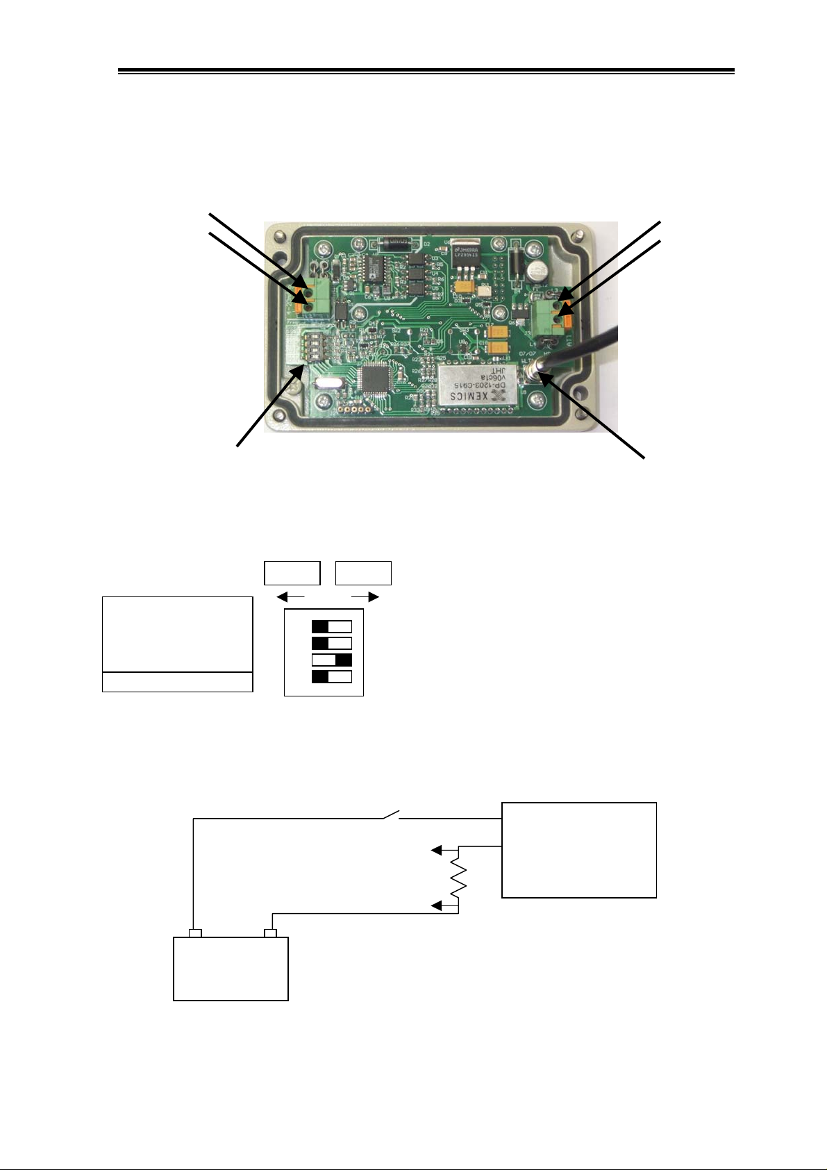
The Wireless Level Receiver has an optically isolated 4-20mA output that is powered by the
external 4-20mA power.
4-20mA output +
4-20mA output -
Freq 0 1 2 3 4 5 6 7
1: 0 1 0 1 0 1 0 1
2: 0 0 1 1 0 0 1 1
3: 0 0 0 0 1 1 1 1
=
Configuration
DIP Switches
=
Wireless Level
Receiver
DIP Switches 1,2,3 set the transmission frequency
=
1
2
3
4
=
Switched
Power
Measure
and DIP switch 4 sets the frequency band for :
USA and Australia.
0 = 905.5MHz 917.5MHz
1 = 906.5MHz 918.5MHz
2 = 907.5MHz 919.5MHz
3 = 908.5MHz 920.5MHz
4 = 909.5MHz 921.5MHz
5 = 910.8MHz 922.5MHz
6 = 911.9MHz 923.5MHz
7 = 912.5MHz 924.5MHz
4-20mA output +
+
4-20mA output -
Battery +
Battery -
Aerial
+
Battery
Wireless Level Transmitter
© Copyright
-
Wireless Level
Receiver
WLT420 100-6 Issue 1.20 5 Dec, 2007
Page 7
Hydrological Services Pty Ltd
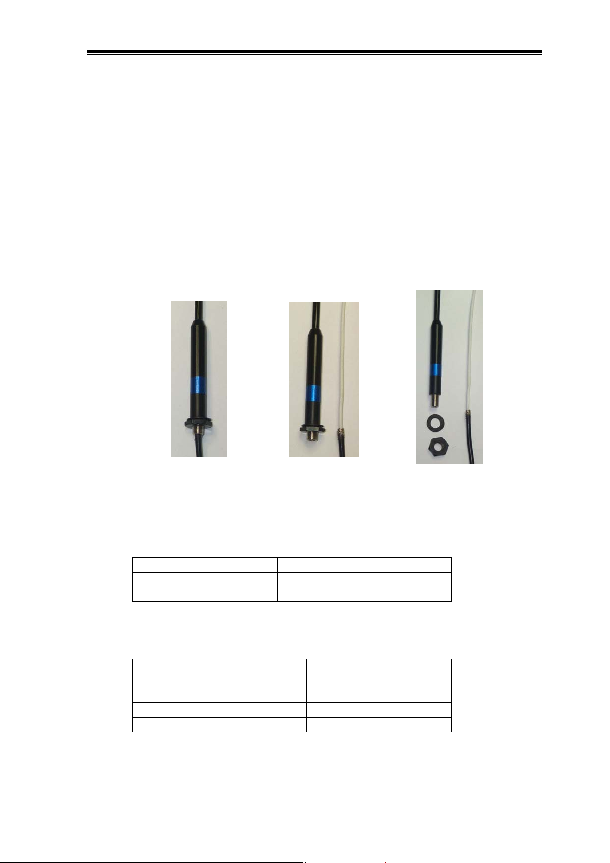
2.2 Antenna Mounting
Both the transmitter and receiver are supplied with a ground plane independent antenna that
have 1.5dB gain. (The mounting thread of the antenna is connected to the battery –ve input.)
The antenna is mounted by :
• Hold the antenna coax cable firmly and unscrew the antenna body.
• Remove the nut and washer from the antenna body and put onto the coax cable.
• Drill a 10mm mounting hole.
• Insert the coax cable through the mount hole – from the inside of the enclosure.
• Screw the antenna body back onto the coax cable.
• Insert the antenna into the mounting hole and slide the washer and nut onto the
antenna body and tighten the nut.
2.3 Power Supply
The Wireless Level Transmitter requires a 12V power source, such as a 7Ah lead acid
battery. The transmitter has 2 basic states, sleep and warm up.
Tx Mode Current Consumption
Sleep 0.15A
Warm Up 10mA + measured 4-20mA
The Wireless Level Receiver also requires a 12V power source, such as a 7Ah lead acid
battery. The receiver has 4 basic states.
Rx Mode Current Consumption
Sleep (with no 4-20mA power) 0.1mA
Sleep (with 4-20mA power) 0.6mA
LCD on (backlight off) 20mA
LCD on (backlight on) 75mA
Wireless Level Transmitter
© Copyright
WLT420 100-7 Issue 1.20 5 Dec, 2007
Page 8

Hydrological Services Pty Ltd
3. Operation
DIP Switches 1 to 4 on the transmitter and receiver MUST be set the same, so that both units
are set to the same frequency. If multiple units are required in the same vicinity, then set them
to a different frequency. Note that the units use a license free band – however, these bands are
different in Australia and the USA, so make sure DIP switch 4 is set appropriately.
The transmitter sends the 4-20mA current measured, switch settings, battery voltage and the
software revision. This information is all displayed on the receiver LCD.
When the transmitter is set to continuous transmit mode, the receiver LCD recognises this
and stays on permanently. This mode is useful when testing the WLT420. When the
transmitter is set to transmit every 1min, 15 mins or 60 mins then the receiver will
automatically go to sleep, and then automatically wake up the RF circuitry ready to receive
the next expected message – the receiver will stay awake until the message is received. When
a message is received the status LED on the WLT420R Receiver will flash.
3.1 Transmitter LED
The transmitter LED indicates what state the transmitter is in.
LED Description
Flashes every 2 secs Transmitter is asleep
Flashes fast Transducer has power applied – in warm up mode
On Steady Measuring transducer 4-20mA for 1 sec, then transmits result
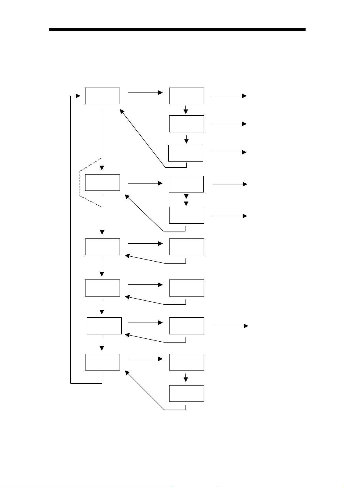
3.2 LCD Navigation
Press either button to wake up the receiver for 30 secs. The backlighting will also come on for
5 secs. The display will be continually updated as new data is received. Press the scroll
button to step through the most commonly used menu items. Press the select button for 5
seconds to step to special menus as shown.
Use the Set Level menu to set the measured water level. This will automatically calculate an
appropriate offset and add it to the measured 4-20mA level. Scroll to the Offset menu to view
this calculated offset. The Offset may be zeroed by pressing the scroll button for 5 secs.
The Range menu allows the transducer range to be set.
The Last Rx menu shows the last time an RF message was received in hrs:mins:secs. This
will allow you to see if messages are being received correctly. The TxIntvl and Warm Up
menus show you the present positions of the WLT420 transmitter DIP switches.
Wireless Level Transmitter
© Copyright
WLT420 100-8 Issue 1.20 5 Dec, 2007
Page 9
Hydrological Services Pty Ltd
NOTE : No text on arrow => Press Scroll button
Sel 5 sec => Press Select button for 5 secs
Skip if
VolDsply
Disabled
Water Lvl
Volume
My BattV
Sel 5 sec
Sel 5 sec
Sel 5 sec
Set Level
Offset
-
VolDsply
Poly-0
Poly-4
My S/W
Select
Sel 5 sec
Select
Select
Select
Edit Set Level
Zero Offset
Edit Volume Display
Enabled / Disabled
Edit Polynomial Term 0
:
:
Edit Polynomial Term 4
Rem BatV
4-20mA
Last Rx
Sel 5 sec
Sel 5 sec
Sel 5 sec
Rem S/W
Range
TxIntval
WarmUp
Select
Edit Range
Wireless Level Transmitter
© Copyright
WLT420 100-9 Issue 1.20 5 Dec, 2007
Page 10

Hydrological Services Pty Ltd
3.3 Displaying Water Volume
The WLT420 has the facility to display the water volume (of a reservoir) as a function of the
water level. See Appendix B for details on how to derive the appropriate equation and hence
the terms of the 4th order polynomial Poly0 thru to Poly4. The formula generated in the
example is :
Water Volume = 0.8065 x4 - 18.957 x3 + 165.76 x2 - 19.588 x + 0.000
(where x is the water depth in metres)
For this example, the polynomial terms entered into the WLT420 are as follows :
(Please note the sign of each term !!!!!)
Poly0 = 0.000 ( term for x0, which is the intercept )
Poly1 = - 19.588 ( term for x1, which is just x )
Poly2 = 165.760 ( term for x2 )
Poly3 = - 18.957 ( term for x3 )
Poly4 = 0.8065 ( term for x4 )
The Volume display option must first be enabled. (Examine the LCD navigation chart on the
previous page.)
• Press the Scroll button and step to the “WaterLvl” menu.
•
Press and hold the Select button for 5 secs until the “SetLevel” menu appears.
•
Press the Scroll button twice and advance to the “VolDsply”.
•
Press the Select button to start the “Disabled” flashing.
• Press the Scroll button to select “Enabled” flashing.
• Press the Select button to stop the flashing.
• Press Scroll button to save the VolDsply enabled feature.
• Press the Scroll button to advance to the “Volume” display.
• Press and hold the Select button for 5 seconds until the “Poly0” menu appears.
• Press the Select / Scroll / Select buttons to advance each digit of Poly0.
• Press the Scroll button to step to “Poly1”
• Repeat the previous steps to set Poly1, Poly2, Poly3 and Poly4.
• Press Scroll to step back to the “Volume” display.
• The water volume should now be displayed.
By using the “Set Level” menu item, you can preset various levels and hence check the Water
Volume. As the water level now changes between 0.000m and 10.000m the water volume of
the reservoir will be displayed.
The water volume created from this 4
approximation.
th
order polynomial is not exact – but it is a very good
Wireless Level Transmitter
© Copyright
WLT420 100-10 Issue 1.20 5 Dec, 2007
Page 11

Hydrological Services Pty Ltd
4. Specification
4.1 Hardware Specification
Transmitter Inputs 4-20mA Input (12 bit resolution : 256 samples over 1 sec)
Receiver Outputs 4-20mA Output (16 bit resolution)
Indicators WLT420T Transmitter - Status LED indicator
WLT420R Receiver – Status LED + 8 char x 2 line LCD
Displays Water Level, Volume, Battery Voltage, …
Controls WLT420R Receiver – Scroll + Select pushbuttons
Connections Screwless Terminals
Radio Frequency US 905.5 to 912.5MHz
AUS 917.5 to 924.5MHz
Transmit Power 10mW
Range 1km (0.62 miles) line of sight
Dimensions 125mm x 80mm x 57mm (L x W x D)
Weight WLT420T Transmitter with aerial 600 grams
WLT420R Receiver with aerial 620 grams
Environmental -40C to + 70C at 95% RH Non Condensing
Aluminium waterproof housing IP67
Wireless Level Transmitter
© Copyright
WLT420 100-11 Issue 1.20 5 Dec, 2007
Page 12
Hydrological Services Pty Ltd
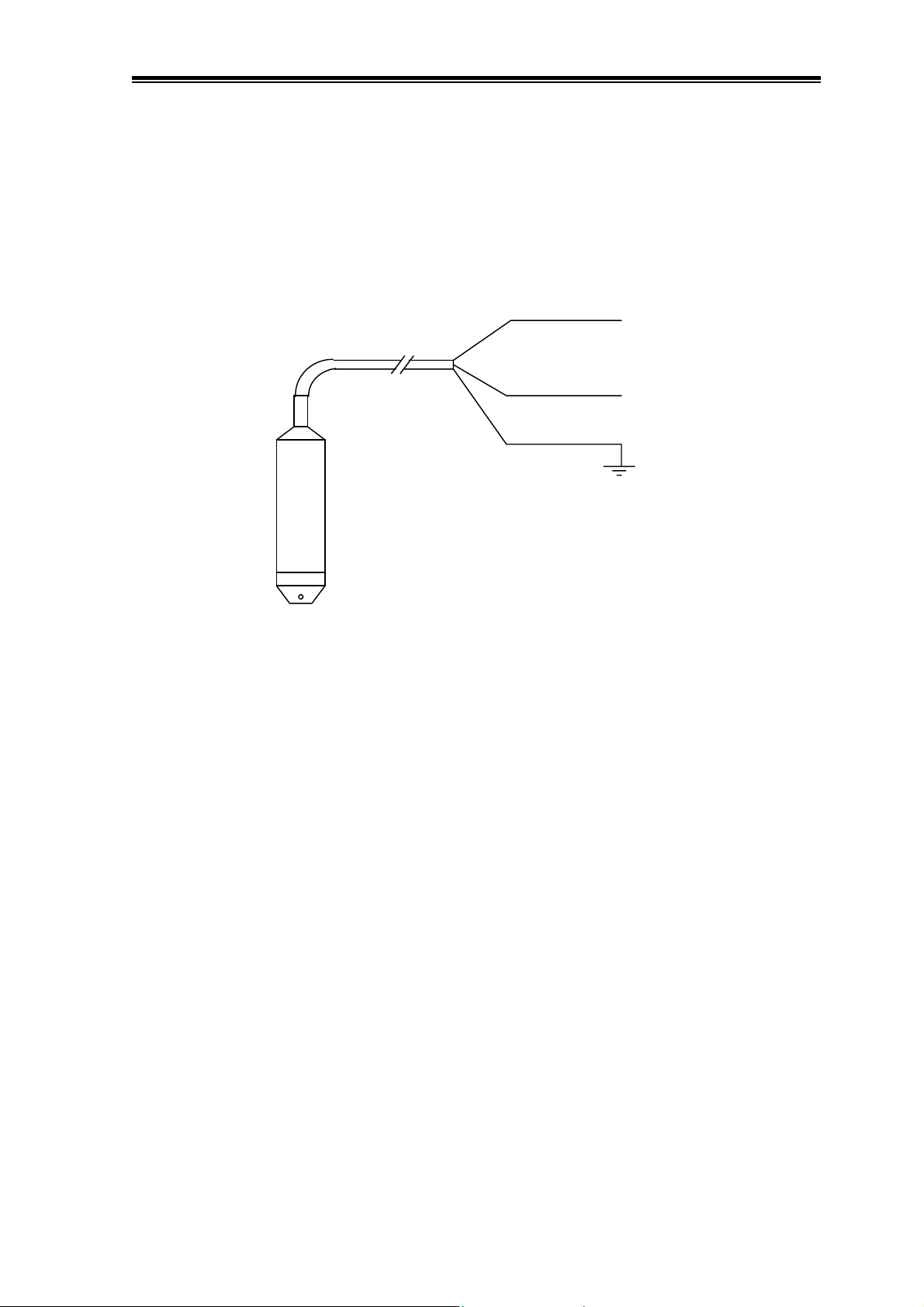
Appendix A Connecting a WL1200W Transducer
Brown
Green
Blue
Transducer +
Transducer -
Earth Screen
Wireless Level Transmitter
© Copyright
WLT420 100-12 Issue 1.20 5 Dec, 2007
Page 13
Hydrological Services Pty Ltd
Appendix B Creating the Level to Volume Formula
The WLT420 has the facility to display the water volume (of a reservoir) as a function of the
water level. The function implemented is a 4th order polynomial. This appendix shows how to
generate the formula from a “level : volume” data table.
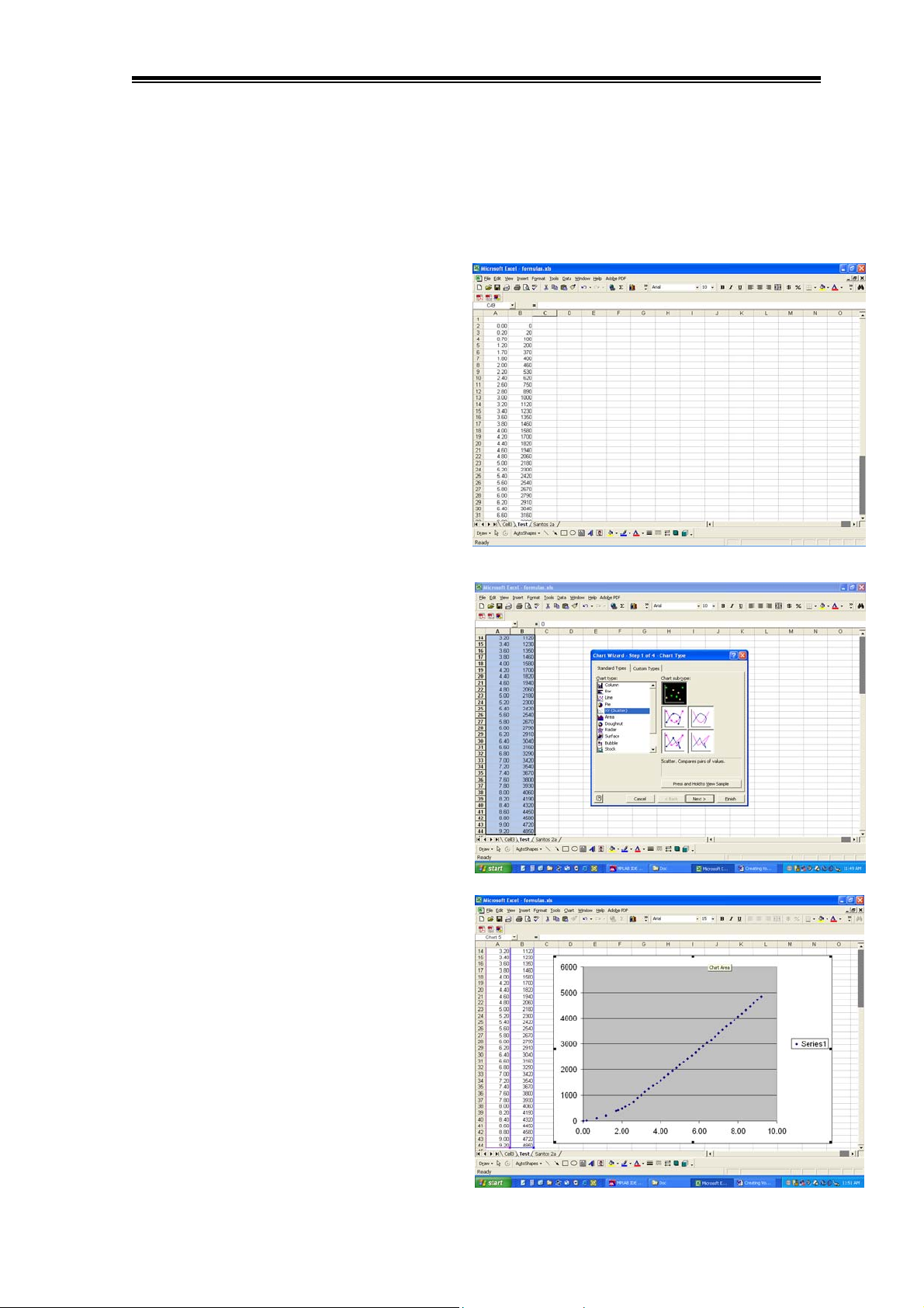
After a site survey, a table of data equating
water level (in metres) to water volume (in
mega-litres) should be entered into an Excel
spreadsheet as shown
(This procedure assumes the water volume
is always in mega-litres.)
Select the data, then click on the “Chart
Wizard” or select the menu item “Insert –
Chart”.
Click on XY (Scatter) and click finish.
This will automatically create a graph of
points relating water level (x axis) to the
water volume (y-axis).
Position and size the graph on the
spreadsheet page.
Wireless Level Transmitter
© Copyright
WLT420 100-13 Issue 1.20 5 Dec, 2007
Page 14
Hydrological Services Pty Ltd
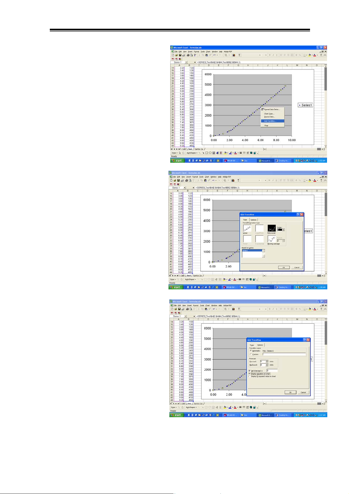
Click on one of the graph points, then
right click and select “Add trendline…”
Click on Polynomial and increase
“Order” to 4 (to create a 4th order
polynomial)
Click on the “Options” tab.
Select “Set intercept =” and then enter
the water volume when the water level is
0.00m
Select “Display equation on chart”
Click OK
Wireless Level Transmitter
© Copyright
WLT420 100-14 Issue 1.20 5 Dec, 2007
Page 15
Hydrological Services Pty Ltd
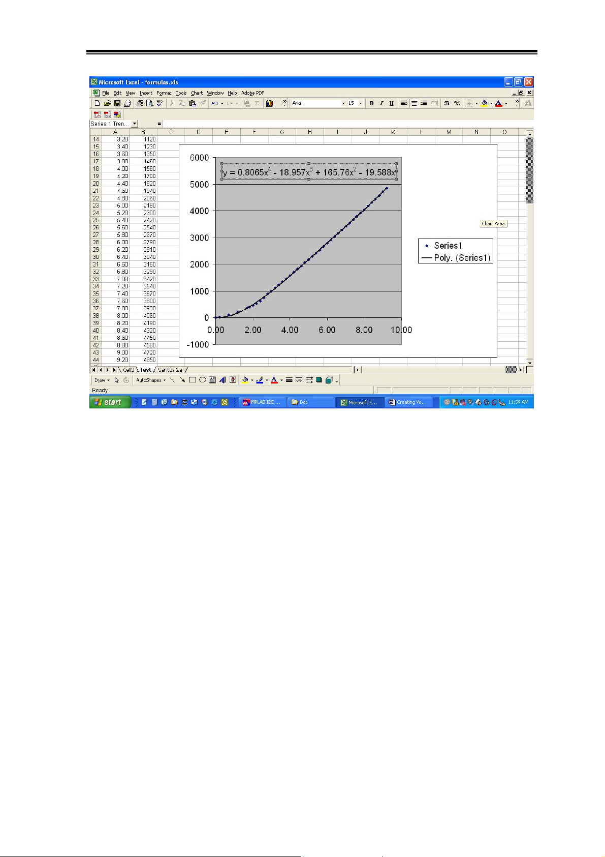
The line drawn on the chart is the 4th order polynomial. You should get a good idea of how
well the formula fits the tabled data.
The formula generated in this case is :
Water Volume = 0.8065 x4 - 18.957 x3 + 165.76 x2 - 19.588 x + 0.000
(where x is the water depth in metres)
For this example, the polynomial terms entered into the WLT420 are as follows :
(Please note the sign of each term !!!!!)
Poly0 = 0.000 ( term for x0, which is the intercept )
Poly1 = - 19.588 ( term for x1, which is just x )
Poly2 = 165.760 ( term for x2 )
Poly3 = - 18.957 ( term for x3 )
Poly4 = 0.8065 ( term for x4 )
As the water level now changes between 0.000m and 10.000m the water volume of the
reservoir will be displayed.
The water volume created from this 4th order polynomial is not exact – but it is a very good
approximation.
Wireless Level Transmitter
© Copyright
WLT420 100-15 Issue 1.20 5 Dec, 2007
 Loading...