

HYDROLOGICAL SERVICES ML1-420 Operation Manual

Hydrological Services Pty Ltd
1
MiniLog
Digital + 4-20mA + BattV + TempC Data Logger
Model : ML1-420
Operation Manual
HYDROLOGICAL SERVICES Pty Ltd
48-50 Scrivener Street
Liverpool NSW 2170
Australia
Ph. 61 2 9601 2022 Fax. 61 2 9602 6971
E-Mail: sales@hydrologicalservices.com

Hydrological Services Pty Ltd
Data Logger Model ML1-420
© Copyright
ML1-420 100-2 Issue 1.00 6 Apr, 2011
TABLE OF CONTENTS
1. Introduction ......................................................................................................... 3
2. Product Overview ................................................................................................ 4
2.1 Overview ............................................................................................................... 4
3. Installation ............................................................................................................ 4
3.1 Hardware Connections ....................................................................................... 5
3.1.1 Contact Closure input ......................................................................................... 6
3.1.2 External Power Supply ....................................................................................... 6
3.1.3 4-20mA Transducer Input .................................................................................. 7
3.1.4 Communications .................................................................................................. 7
3.2 Setup and Configuring the Logger .................................................................... 9
3.2.1 Site Information ................................................................................................... 9
3.2.2 System Time/Date ................................................................................................ 9
3.2.3 Sensor + Parameters ............................................................................................ 9
3.2.4 Communications .................................................................................................. 10
4. Operation .............................................................................................................. 11
4.1 Commands / Syntax ............................................................................................. 11
4.1.1 On-line Help (?) ................................................................................................... 11
4.1.2 Communications (BAUD, EV, RE, CLEAR) .................................................... 12
4.1.3 Battery Voltage (BV, BVINT) ............................................................................ 13
4.1.4 Temperature (TEMPC) ...................................................................................... 13
4.1.5 Digital Channel Parameters (CHID, INC, TDAY, TOT, TYPED, UD) ......... 14
4.1.6 4-20mA Channel Parameters (CHIDRV, RVHR, TXI, …..U420, WL) ......... 15
4.1.7 Date/Time Parameters (D, FMT, T, TA) ........................................................... 17
4.1.8 Dump Log Records (DUR, DURV, ….DUALL, CLR, CLRV, MW, LOG) .. 18
4.1.9 Miscellaneous (ID, SI, PASSWD, BYE, SLEEP, RESET, VER) .................... 21
4.1.10 Status Window (ST) ............................................................................................... 22
4.2 Data Output Format ............................................................................................ 24
4.2.1 Dump Log Record ............................................................................................... 24
5. Specification ......................................................................................................... 27
5.1 Hardware Specification ....................................................................................... 27
5.2 LED Indicator ...................................................................................................... 28
5.3 External Contact Interface ................................................................................. 28
5.4 4-20mA Interface ................................................................................................. 28
5.5 Communications Interface.................................................................................. 28
5.6 Watchdog .............................................................................................................. 28
6. Fault Finding ........................................................................................................ 30
Appendix A. Interfacing to a Modem .................................................................................. 32
Appendix B. Installing a RainTrak System ........................................................................ 35
Appendix C. Surge Protection .............................................................................................. 37
Hydrological Services Pty Ltd
Data Logger Model ML1-420
© Copyright
ML1-420 100-3 Issue 1.00 6 Apr, 2011
1. Introduction
The Hydrological Services MiniLog Data Logger ML1-420 has been designed using surface
mount technology to provide a very small, ultra low power and reliable data logger that can
be used in harsh environments for extended periods. Flash memory technology has not only
been used for data storage but also for program storage - which provides secure non-volatile
data storage as well as the unique capability of software download as new software features
and revisions become available. The logger can be connected to a standard Tipping Bucket
Rain Gauge OR any device that requires a contact closure to be monitored – it monitors the 420mA signal from a water level transducer, an external 12V battery, the internal battery and
the ambient temperature inside the MiniLog enclosure. The communication features allow for
very flexible operation directly connected to a computer. The unique on-board help feature
allows the user to obtain a list of commands with syntax. The ultra low power allows the
logger to be powered from an internal 3.6V AA lithium battery for 2 years or a 1.5V AA
alkaline battery for 1 year. The indicator LED flashing once a second as a heartbeat, gives the
user confidence that the MiniLog is alive and well.
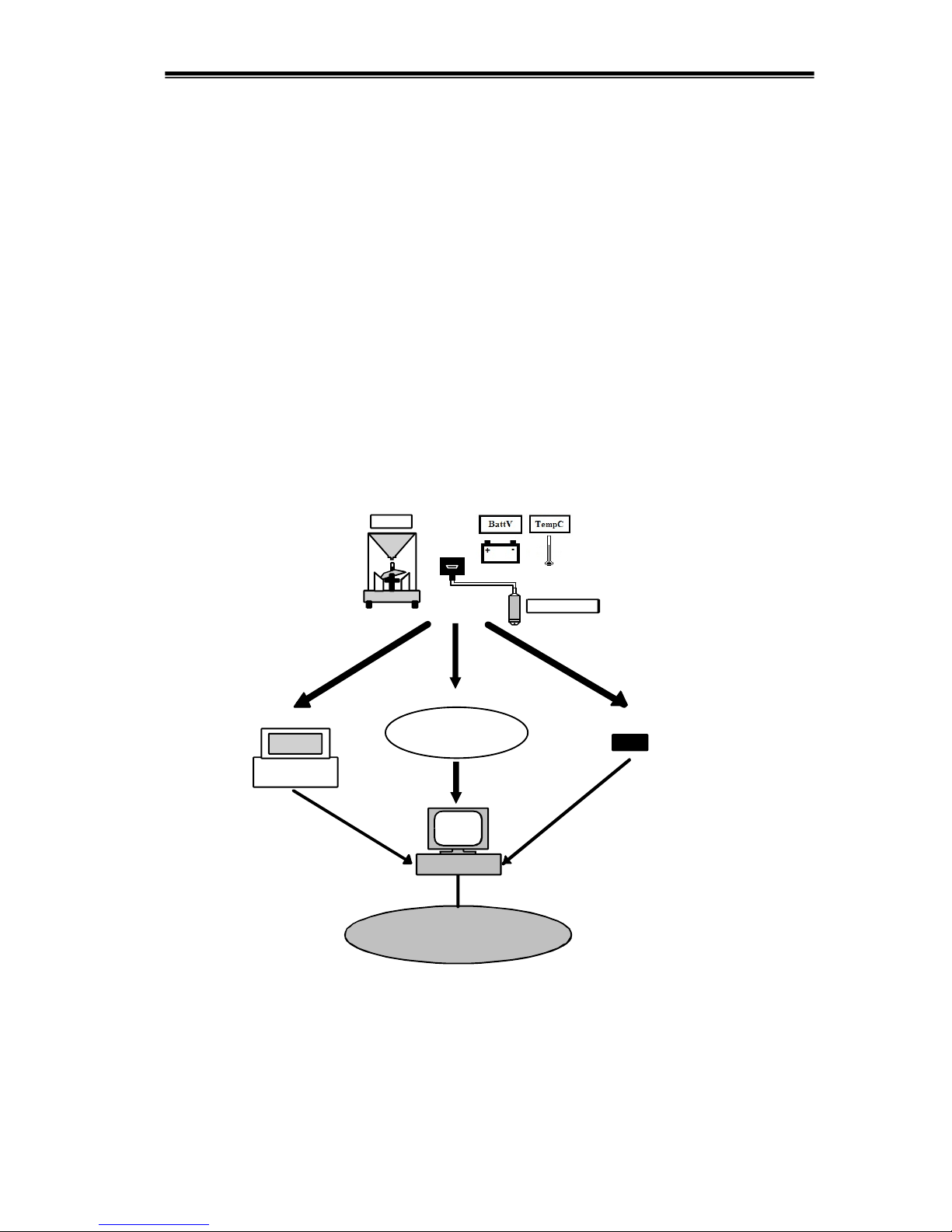
LAN / WAN
PORTABLE PC
OR
ML1-420
Logger
Logger returned Unload at site
PC
TBRG
(If applicable)
OR
Communication
Interface
PSTN, GSM, Satellite
River Height
4-20mA Sensor
Hydrological Services Pty Ltd
Data Logger Model ML1-420
© Copyright
ML1-420 100-4 Issue 1.00 6 Apr, 2011
2. Product Overview
2.1 Overview
The Hydrological Services MiniLog Data Logger is easily installed within many products due
to its small size. Its primary purpose is to count contact closures and measure and log data
from a 4-20mA sensor / transducer.
One such application would be inside a Tipping Bucket Rain Gauge, (TBRG). Rain falling
on the collecting funnel is directed through a syphon control unit and discharges as a steady
stream into a 2 compartment bucket mounted in unstable equilibrium. As each compartment
fills, the bucket tilts alternately about its axis. Each tip forces a contact closure of a magnetic
reed switch corresponding to a height of rainfall depending on bucket capacity, (Bucket
Capacity can be 0.2 mm, 0.5 mm, 1.0 mm, 0.01 inch). The logger unit accepts the contact
closure and records the event as a time stamp to one second resolution. Each event is stored
in secure, non-volatile flash memory.
At the same time the logger can measure water level using a 4-20mA pressure transducer.
The logger switches the external 12V battery voltage to the 4-20mA loop, and waits the
required warmup period, takes a measurement of the 4-20mA current, turns off the loop
power, scales the result and saves each measurement in secure, non-volatile flash memory in
preparation for data extraction.
The data extraction process is accomplished via a PC or similar. A simple one-to-one DB9
cable connection is made between the PC and logger to allow data retrieval upon operator
command. The data format of the logger file is specified within this document.

Hydrological Services Pty Ltd
Data Logger Model ML1-420
© Copyright
ML1-420 100-5 Issue 1.00 6 Apr, 2011
3. Installation
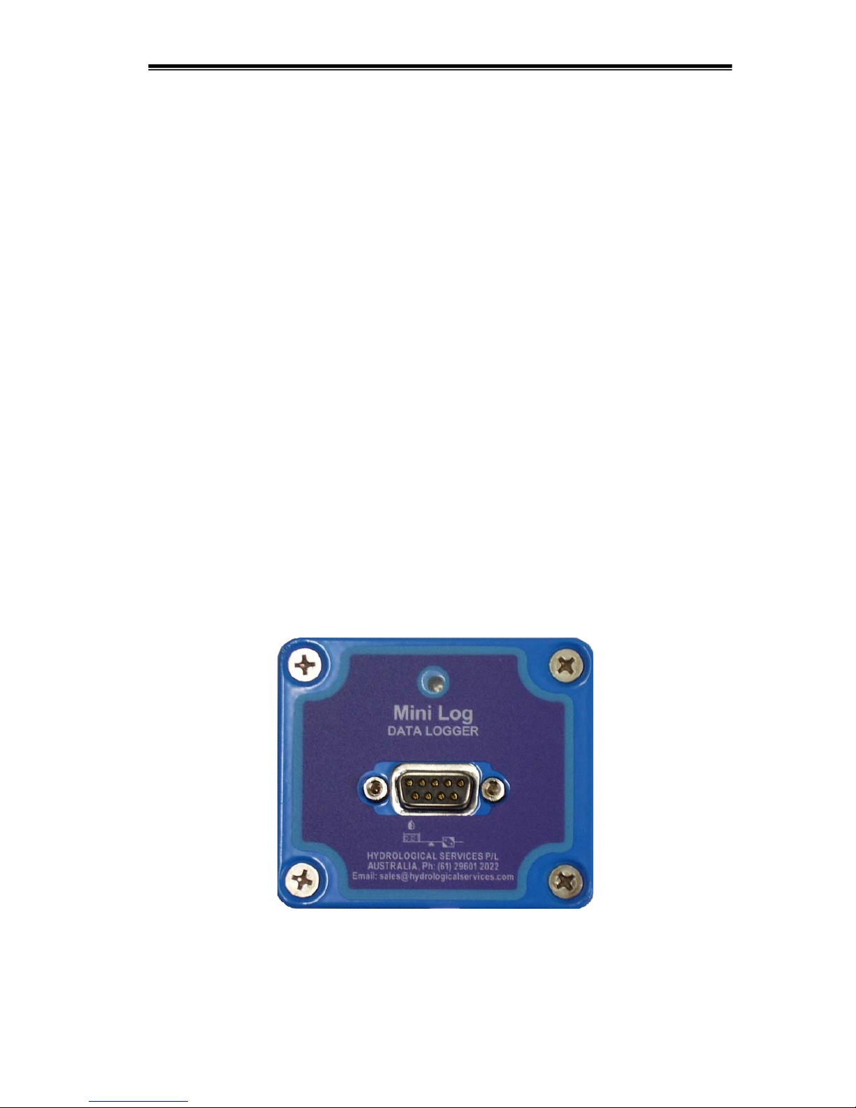
The MiniLog has a single DB9 female connector, which is mainly used for communications –
(the digital input and external power may be taken through this connector, making it pin
compatible with the ML1). The pinout is designed to be compatible with direct connection to
a PC Comm port. Note that when external power is supplied, whether though an external 12V
battery or RS232 handshake lines, the power drawn from the internal battery is reduced to
zero.
The digital input from the TBRG, external 12V power and the 4-20mA transducer are
connected to the internal screwless terminal blocks – these specific terminals are used
because they keep a constant tension on the wires that are inserted.
1. Use a small flat blade
screwdriver and pushdown on the oran
g
e
2. Insert the stripped
3. Release the orange
lever to secure the wire.
4. Pull on the wire to
TBRG
12V
Battery
WL3100
AD375MA
ML1-420
4-20mA
“OR”
Submersible
4-20mA
Pressure
Transducer
Model: PS98i
“ML1-420 Typical Application”
Rainfall
Water Level
Hydrological Services Pty Ltd
Data Logger Model ML1-420
© Copyright
ML1-420 100-6 Issue 1.00 6 Apr, 2011
3.1 Hardware Connections
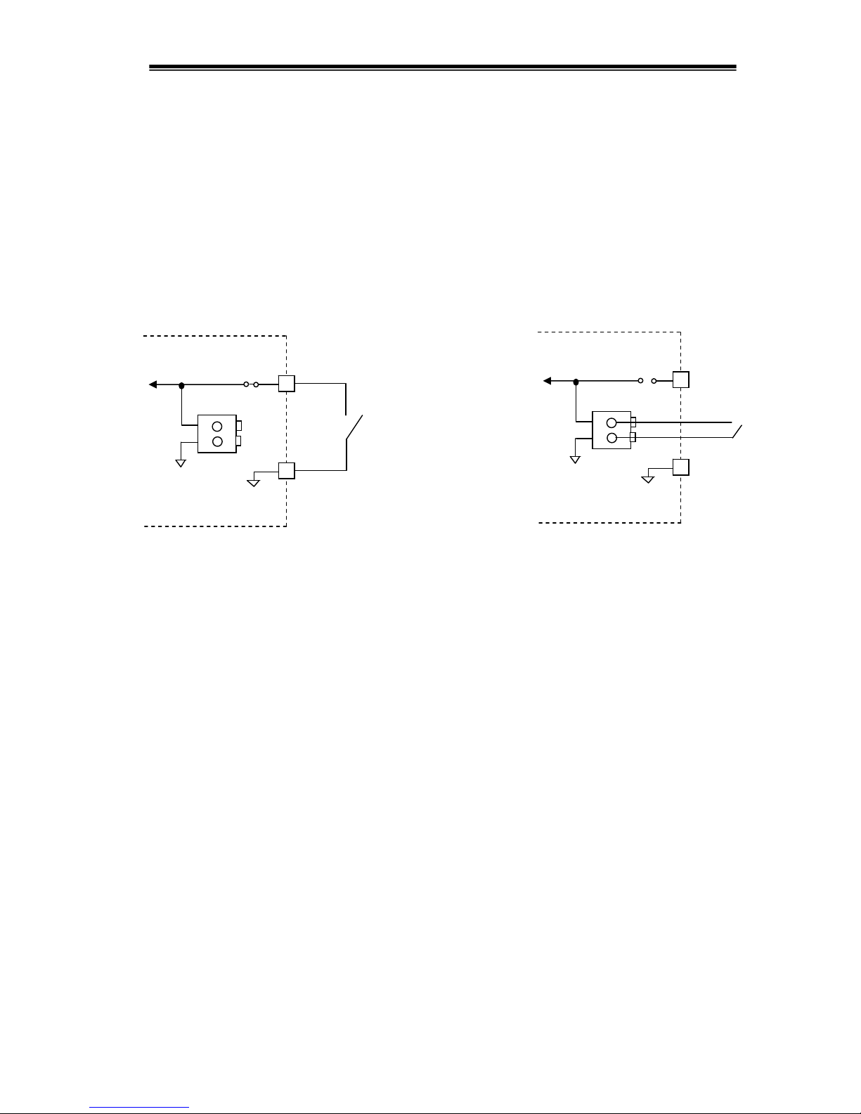
3.1.1 Contact Closure input
The voltage free contact to be monitored should be connected either between Pin 9 (contact
closure input) and Pin 5 (Gnd) with PCB solder link LK1 bridged OR it can be connected
to the internal screwless terminal block, through a cable gland on the enclosure. (Note that
the PCB solder link LK1 is an option that is left open circuit when the ML1-420 is supplied
from the factory.) (Also Note: In the first option (shown on the left), an extra tip will be
generated when the DB9 connector is plugged into a PC, unless pin 9 is clipped on the DB9
lead.)
Connection of Contact Closure Input
3.1.2 External Power Supply
While the MiniLog ML1-420 is in the field monitoring a 4-20mA transducer, an external 12V
power source must be connected to provide power to the transducer. The logger switches the
12V to the transducer, and waits for the preset warmup period (as set by the TXI parameter),
and then measures the 4-20mA current that is passing through the sense resistor. The logger
only uses the internal battery for maintaining the time while there is no external power source
present.
The ML1-420 draws power from the RS232 signals for communications when there is no
external power source present. (Note that this is not sufficient to power a 4-20mA
transducer.)
The internal and external voltage is measured and logged periodically by the logger. The
logging interval is set with the “BVINT” command, which can be set from 1 to 999 minutes.
The logged data can be retrieved with the DUBVI (internal battV) command, DUBVE
(external battV) command, DUBVT (battV and tempC) command or the DUALL (dump All)
command.
While the MiniLog ML1-420 is in the field monitoring the contact closure only, an external
power supply is not required. The logger enters a “sleep” mode, waking only to update the
time, and log a contact closure event. In this mode the logger will operate continuously for 2
years on the internal 3.6V lithium battery (or 1 year on a 1.5V alkaline battery).
External
Voltage
Free
Contac
t
9
5
MiniLog
ML1-420
DB9 pins
LK1
Screwless
terminals
Monitor
Circui
t
OR
External
Voltage
Free
Contac
t
9
5
MiniLog
ML1-420
LK1
Screwless
terminals
Monitor
Circui
t
Hydrological Services Pty Ltd
Data Logger Model ML1-420
© Copyright
ML1-420 100-7 Issue 1.00 6 Apr, 2011
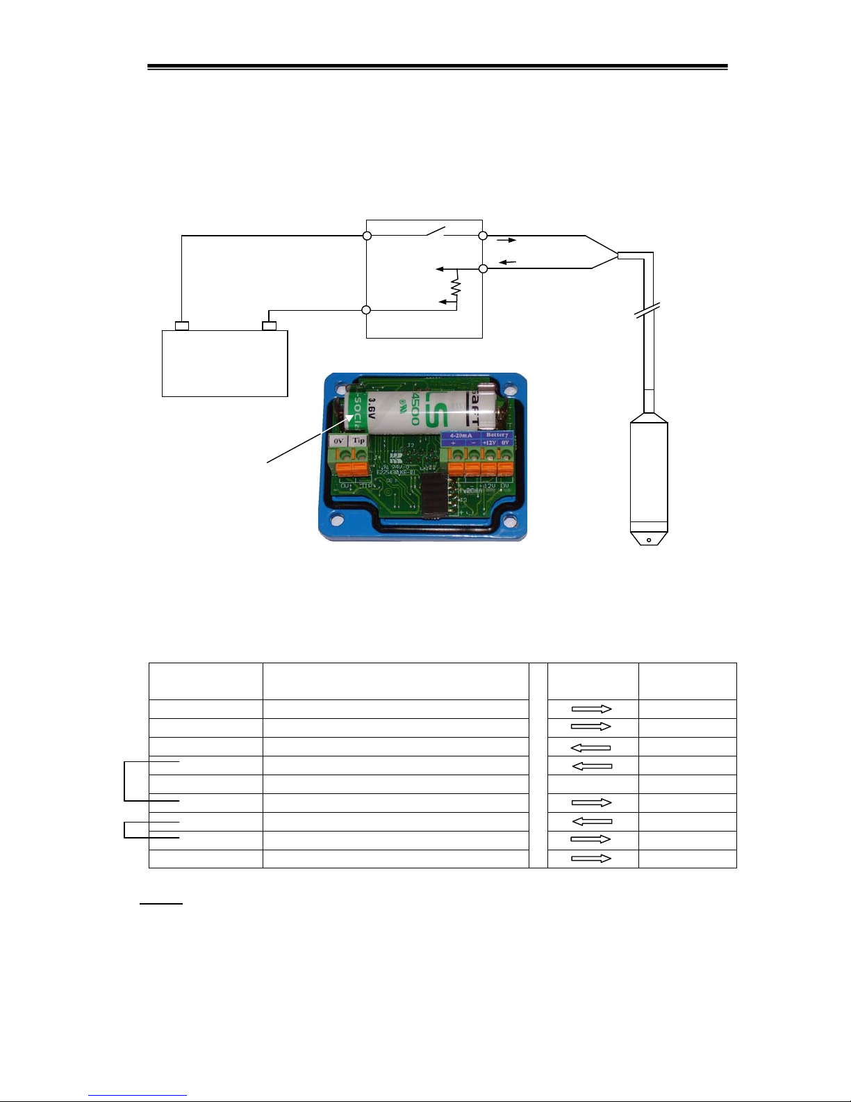
Internal battery
for maintaining
time when no
external power
is present !
ML420
Sense
Brown
4-20mA
Transducer
Green
4-20mA+
12V Battery
-
+
Batt +12V
Batt 0V
4-20mA-
3.1.3 4-20mA Transducer Input
The 4-20mA connection is via 2 wires into a screwless terminal block. The battery voltage is
switched to the 4-20mA transducer and the current is measured across an internal sense
resistor.
Connection of 4-20mA Transducer
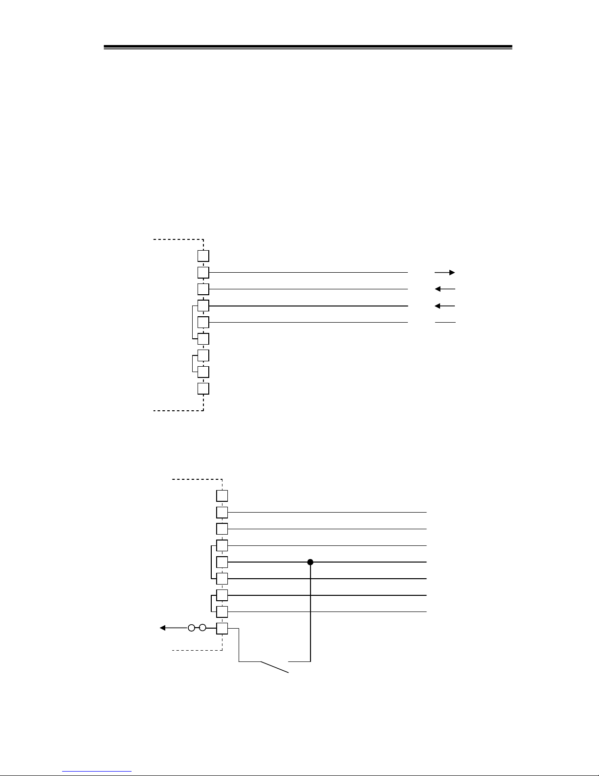
3.1.4 Communications
The pinout of the DB9 female connector on the front of the ML1-420 logger is as follows :-
Pin
Connection
ML1-420 Logger Signal Name
DB9 Female
PC Signal
Direction
PC Signal
DB9 Male
1 No Connection CD
2 Tx (RS232 Serial data output) Rx
3 Rx (RS232 Serial data input) Tx
4 External Power (+ DTR / DSR loop) DTR
5 Gnd Gnd
6 External Power (+ DSR / DTR loop) DSR
7 External Power (+ RTS / CTS loop) RTS
8 External Power (+CTS / RTS loop) CTS
9 Contact closure input (See note 3) RI
Notes:
1. When the ML1-420 is directly connected to a PC the following handshake signals are
linked
Pins 4 and 6 are linked together inside the ML1-420.
Pins 7 and 8 are linked together inside the ML1-420.
Hydrological Services Pty Ltd
Data Logger Model ML1-420
© Copyright
ML1-420 100-8 Issue 1.00 6 Apr, 2011
2. When the ML1-420 is directly connected to a PC, sufficient power is extracted from the
handshake signals to power the ML1-420 – which prevents power drain from the internal
battery while communications is in progress.
3. A solder link LK1 on the ML1-420 PCB allows the digital input from the TBRG to be
connected through pin 9 of the DB9F connector. See section 3.1.1 for more details.
The DB9 female connector on the logger is the communications port and is setup as a DCE.
This allows direct connection to a PC comm port using a DB9 male to DB9 female 1-to-1
cable. (The minimum connection is pins 2, 3, 4 and 5.)
Minimum Connection of PC on DB9F
Communications can also be active while the contact closure input on pin 9 is used when
jumper LK1 is soldered, and a special cable is prepared.
Connection of PC together with Contact Closure Input through the DB9F
PC
Comm
Port
1
8
MiniLog
ML1-420
2
3
4
5
6
7
9
DB9
Female
1
8
2
3
4
5
6
7
9
DB9
Male
PC
Comm
Port
1
8
MiniLog
ML1-420
2
3
4
5
6
7
9
DB9
Female
1
8
2
3
4
5
6
7
9
External Voltage
Free Contact
(TBRG)
DB9
Male
Contact
monito
r
LK1
Tx
Rx
DTR
(p
ulled high
)
Gnd

Hydrological Services Pty Ltd
Data Logger Model ML1-420
© Copyright
ML1-420 100-9 Issue 1.00 6 Apr, 2011
3.2 Setup and Configuring the Logger
Once the ML1-420 logger has been connected to a computer, the parameters can be setup
using WinComLog or any ‘dumb’ terminal emulation program. (NOTE: If a third party
application is used, the handshake signals DTR and RTS should be forced high to enable the
MinLog to have power.) If using a third party program, it should be set for the appropriate
baud rate, and 8/N/1 (bits/parity/stop), handshake off, and “local echo on”. On receipt of
individual commands from the computer, the logger will respond with the present parameter
setting. (Note that the command keywords permit both upper and lower case characters, or a
combination of both.) A carriage return ( < CR > , Enter Key) immediately following an
entry will action the command. Invalid entries return a “Command Error” response. A list of
all logger commands may be viewed on the computer screen by using the unique on-board
help system. Simply type ? and then press the Enter key.
Data and parameter security is provided by means of a user password. Any data or
parameters may be viewed without a password, but parameters may only be altered and data
may only be cleared after the password has been entered correctly. The default password
when the logger is supplied is “BOMM”. Parameters may be entered by typing the command,
then the equals symbol (=) and then the new parameter, followed by the Enter key.
3.2.1 Site Information
The “Site Information” (SI) is a user definable 16 character string that allows each logger to
have a unique location name. Alternatively, loggers in a locality may be given the same
name and the rainfall channel ID may be used to uniquely identify the logger data. This
allows for easy identification of dumped data or status window information. See section
4.1.8 for more information on this command.
3.2.2 System Time/Date
The “Time” (T) and “Date” (D) should be checked for accuracy during installation.
The “Time Adjust” (TA) command allows the Real Time Clock to be adjusted for crystal
frequency inaccuracies.
3.2.3 Sensor + Parameters
The Minilog ML1-420 has several parameters that allow characterisation of the sensor being
used. The “Channel ID” (CHID) is a 7 digit user definable number that should be set to
uniquely identify the digital (rainfall) channel. The “Increment” (INC) parameter defines the
capacity of the specific digital sensor used as well as the number of external events that
constitute one logged event - this determines the digital input resolution.
The “River Channel ID” (CHIDRV) is a 7 digit user definable number that should be set to
uniquely identify the 4-20mA (river) channel. The “Transducer Range” (TXR) parameter
defines the 4-20mA Range of the transducer. The “Transducer Interval” (TXI) parameter
defines how often a transducer measurement is taken, and how long the transducer is powered
for. The “River Height Ref” (RvHR) parameter defines the offset of the water height.
See section 4.1.4 for more information on these commands.

Hydrological Services Pty Ltd
Data Logger Model ML1-420
© Copyright
ML1-420 100-10 Issue 1.00 6 Apr, 2011
3.2.4 Communications
The MiniLog ML1-420 has an RS232 serial interface to support asynchronous ASCII
communications to accommodate data extraction and user set-up. This port operates at 1200,
2400, 4800, 9600, 19200, 38400 and 57600 baud with 8 data bits, no parity and 1 stop bit.
If initially you can’t establish communications with the ML1-420, try each of the 7 baud
rates, in case it has been changed from the default rate of 9600.
Each digital input event, and 4-20mA measurement that is logged is also transmitted on the
serial port, unless the event output flag is off (EV=off).
The RS232 serial port interface may be connected to a modem for remote interrogation and
data retrieval – see Appendix A for more details.

Hydrological Services Pty Ltd
Data Logger Model ML1-420
© Copyright
ML1-420 100-11 Issue 1.00 6 Apr, 2011
4. Operation
4.1 Commands / Syntax
The following sections give detailed information on each of the MiniLog ML1-420
commands. Simply type the command and then press enter to view the parameter. To change
a parameter, the password must first be entered, and then type the command followed by =,
then the new parameter followed by Enter. Eg. SI=Sydney then press Enter.
4.1.1 On-line Help (?)
Type a ? then press Enter to get the following help screen. The commands are listed in alphabetical
order.
On-line Help
?
ML1-420 Data Logger Command Syntax [...] = optional to set parameter
(Command may be upper and/or lower case) <CR> = press carriage return
======== General Commands ===================================================
BAUD[=xxxx]<CR> (comms BAUD rate) BYE<CR> (exit passwd access)
CLEARx[=30char]<CR> (Clear Seq.x=1,2,3,4) D[=d/m/y OR m/d/y]<CR> (Date)
EV[=On/Off]<CR> (EVent output) FMT[=dmy/mdy]<CR> (date ForMaT)
ID<CR> (logger ID) LOG[=On/Off] (En/Disable Logging)
MW[=On/Off]<CR> (Memory Wrap) PASSWD=****<CR> (4 char password)
RE[=On/Off]<CR> (REsponse output) RESET<CR> (software RESET)
SI[=16chars]<CR> (SIte name) SLEEP[=N]<CR> (Set Sleep time mins)
ST<CR> (STatus window) T[=hh:mm:ss]<CR> (Time)
TA[=hh:mm:ss] (Time Adjust) VER<CR> (s/w VERsion)
======== Battery Voltage and Temperature Commands ===============================
BV<CR> (Batt. Voltages now) BVINT[=mmm] (BV/TempC log INTerval)
TEMPC<CR> (TEMPerature oC now)
======== Digital Input Commands ==============================================
CHID[=7 dig]<CR> (CHannel ID - Digital) INC[=x.x/mm]<CR> (INCrement+mult.)
TDAY<CR> (Total toDAY) TOT<CR> (TOTal)
TYPED[=16chars]<CR> (TYPE of Dig i/p) UD[=8char]<CR> (Units Di gi t a l )
======== 4-20mA Input Commands =============================================
CHIDRV[=7 dig]<CR> (CHannel ID – 4-20mA) RVHR[=xxx.xxx]<CR> (RiVer Height Ref)
TXI[=mmm/tt]<CR> (Transducer Interval) TXR[=xxx.xxx]<CR> (Transducer Range)
TYPE4[=16chars]<CR> (TYPE of 4-20 logger) U420[=8char]<CR> (Units 4-20)
WL<CR> (Water Level now)
======== Dump/Clear Commands ===============================================
CLR<CR> (Clear all Records) CLRV<CR> (Clear all Records)
DUR/N/h:m/d/m/y<CR> (DUmp Rain log) DURV/N/h:m/d/m/y<CR> (DUmp RiVer log)
DUBVI[....]<CR> (DUmp BattV.Internal) DUBVE[....]<CR> (DUmp BattV.External)
DUTMP[....]<CR> (DUmp TempC) DUBVT[....]<CR> (DUmp BattV+TempC)
DUALL[....]<CR> (DUmp ALL Data) (All dump commands have the same syntax)
eg. DUR => Dump all Rainfall data
DUR/3 => Dump last 3 days of Rainfall data
DURV/10/12:00/15/2/11 => Dump 10 days of River data from 12:00 15-Feb-11
--------------------------------------------------------------------------------------------------------------------------Water Level (WL) = (((Measured 4-20mA)-4)/16) x Range (TXR) + Offset (+/-RVHR)

Hydrological Services Pty Ltd
Data Logger Model ML1-420
© Copyright
ML1-420 100-12 Issue 1.00 6 Apr, 2011
4.1.2 Communications (BAUD, EV, RE, CLEAR)
The “Baud” (BAUD) command allows the baud rate to be viewed or changed. Acceptable
baud rates are 1200, 2400, 4800, 9600, 19200, 38400 and 57600.
BAUD<CR> Display the present baud rate
BAUD= 9600<CR> Set the baud rate to 9600 baud
The “Event” (EV) flag allows the time stamps that are transmitted on the serial port to be enabled or disabled.
When an event occurs, the time is transmitted on the serial when EV is on. When EV is off, nothing is
transmitted on the serial port when an event occurs.
EV<CR> Display the state of the event flag.
EV=ON<CR> Enable event reporting
EV=OFF<CR> Disable event reporting
The “Response” (RE) flag allows the error response to commands, to be enabled or disabled.
When RE is on then you may see “Command Error” or “Syntax Error” messages appear if the
MiniLog does not understand what was typed. When RE is off then there will be no response
if the MiniLog does not understand what was typed. It is useful to turn this off when
connected to a modem, so that the MiniLog and the modem don’t engage in endless
“Command Error” conversations.
RE<CR> Display the state of the response flag.
RE=ON<CR> Enable all error responses.
RE=OFF<CR> Disable all error responses.
The “Clear” (CLEAR1/2/3/4) command sequences are used to control an external modem –
that is, force it into a known state. (If there is no modem connected to your MiniLog, then
these sequences can be left clear. Eg. Set CLEAR1=<CR> then CLEAR2=<CR> then
CLEAR3=<CR> and finally CLEAR4=<CR>)
The Clear sequences are performed when a Bye command is received, and/or if no comms is
received within the Sleep timer period.
There is a maximum of 30 characters in each of the 4 clear sequences. Special characters
include ~ = 0.5 second pause and ^ = CTL character (Eg ^M = carriage return)
The format of each sequence is CLEAR1 = Command Sent / Expected Reply / Timeout
 Loading...