

HydroLogic W-MFI1665GET Operation & Maintenance Manual
Manual for Operation & Maintenance
Of Manganese Greensand
Iron Filter
Model pictured on right is shown with optional Stainless Steel Tank Jacket
for Model:
W-MFI1665GET
Installation and Service Manual – Manganese Greensand Iron Filter
Panel Operation Quick Reference Guide
Manual Regeneration (Backwash)
Note: . If you need to initiate a manual regeneration, either
immediately, or tonight at the preprogrammed time (typically 2
a.m.), complete the following steps.
For Immediate Regeneration: For Regeneration Tonight:
Press and hold and simultaneously until valve
motor starts (typically 3 seconds).
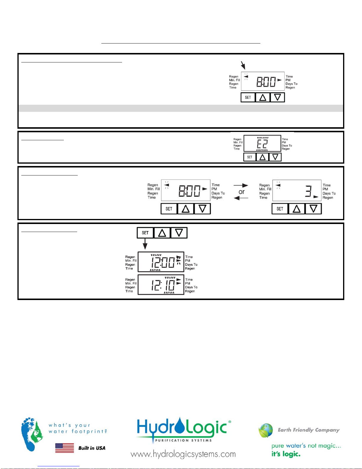
Error Message
If the display shows „E1‰, „E2‰, „E3‰, or „E4‰ (for error), check
the trouble shooting section to identify the error.
General Operation
Arrow will point to Regen if a regeneration is expected „Tonight‰.
When the system is operating one of two
displays will be shown: time of day or days
until the next regeneration.
Pressing or button will toggle between the
two choices.
To Set Time of Day
In the event of a prolonged power
outage, time of day flashes,
indicating that it needs to be reset. All
other information will be stored in
memory no matter how long the
power outage. Please complete the
steps as shown to the right. To access
this mode, press „SET‰.
Arrow will point to Regen if a regeneration is expected „Tonight‰.
Press and release and simultaneously
(notice that arrow points to Regen).
1. Accessed by pressing SET for approximately 3
seconds.
2. Adjust hour with or . With 60 Hz line frequency
detection on power-up, timekeeping is 12 hour with
PM indicator. With 50 Hz line frequency detection
on power-up, timekeeping is 24 hour without the PM
indicator. Press SET to go to the next step.
3. Adjust minutes with or .
4. Press SET to complete and return to normal operation.
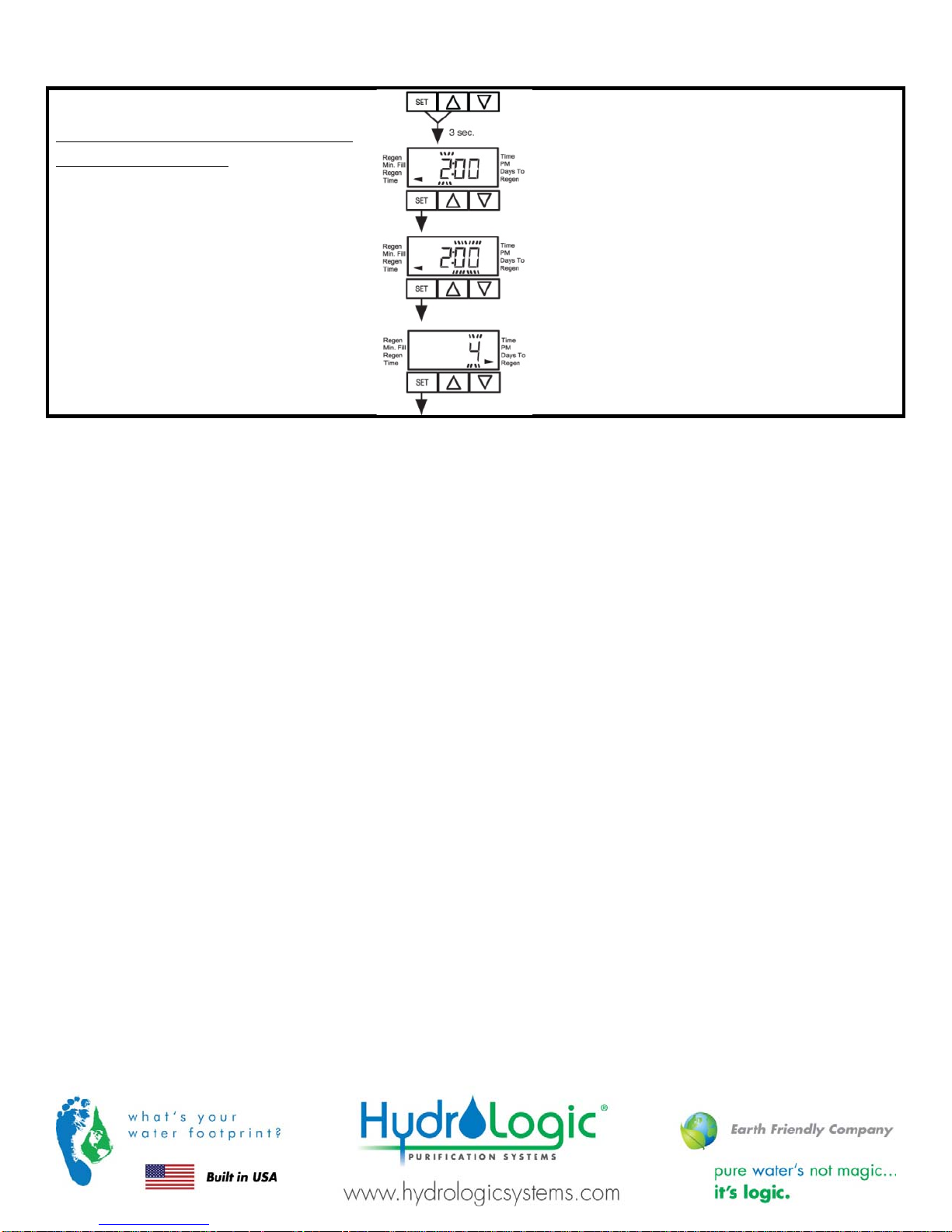
To Set Time of Regeneration and Days
Between Regeneration
For initial set-up or to make adjustments,
please complete the steps as shown.
Access this mode by pressing SET and for
approximately 3 seconds. The number of days
between regenerations may need to be varied
based on usage and water conditions.
(This step will not appear if the 7-day clock
option is selected.)
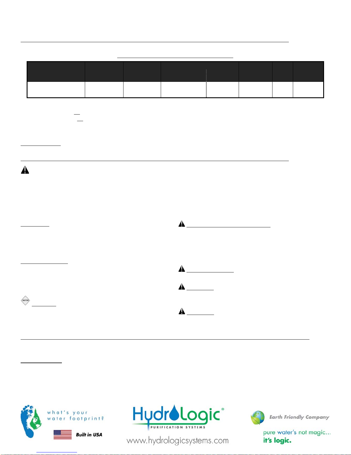
Installation and Service Manual – Manganese Greensand Iron Filter
1. Accessed by pressing SET and simultaneously for
about 3 seconds.
2. Set Regeneration Time Hour. Set the time for
regeneration to start. Press SET to go to the next step.
3. Set Regeneration Time Minutes. Press SET to go to the
next step.
4. Set number of Days between regeneration cycles.
5. Press SET to complete and return to normal operation.
Page 3

Installation and Service Manual – Manganese Greensand Iron Filter
Table of Contents
Design Basis & Specifications ................................................................................................................................. 6
Table 1 Design Basis Specifications ..................................................................................................................... 6
General Information and Safety ............................................................................................................................. 6
Installation .......................................................................................................................................................... 6
Location ............................................................................................................................................................ 6
Loading the Media ............................................................................................................................................. 7
Media Quantity per Model ................................................................................................................................... 8
Plumbing ........................................................................................................................................................... 9
Initial Start-Up ................................................................................................................................................... 10
System Monitoring and Record Keeping ................................................................................................................. 12
Operating Conditions ......................................................................................................................................... 12
Operating DoÊs and DonÊts .................................................................................................................................. 12
Maintenance .................................................................................................................................................... 13
Control Valve Operation & Service ........................................................................................................................ 14
Control Valve Specifications ................................................................................................................................ 14
Panel Operation Quick Reference Guide ............................................................................................................... 15
General Warnings ............................................................................................................................................ 17
Control Valve General Features and Information ...................................................................................................... 17
Programming Control Valve Options ...................................................................................................................... 18
System Setup: Regeneration (Backwash) Cycle Programs ........................................................................................ 18
Installer Displays and Settings for Control Valve Options ........................................................................................... 22
User Displays ................................................................................................................................................... 26
Set Time of Day ................................................................................................................................................ 27
Power Loss ...................................................................................................................................................... 27
Error Messages ................................................................................................................................................ 27
Control Valve Drawings and Components ............................................................................................................... 28
Front Cover & Drive Assembly ............................................................................................................................. 28
CV1TC Drive Cap Assembly, Downflow Piston, Regenerate Piston & Spacer Stack Assembly .......................................... 29
Injector Cap, Injector Screen, Injector, Plug and O-Ring ............................................................................................ 31
Refill Flow Control Assembly and Refill Port Plug ...................................................................................................... 32
Drain Line Flow Controls 1‰ .............................................................................................................................. 33
CV1 with 1.050‰ Distributor Tube Opening Identification ......................................................................................... 35
Installation Fitting Assembly ................................................................................................................................. 35
Flow Diagram, Service....................................................................................................................................... 36
Flow Diagram, Backwash ................................................................................................................................... 37
Flow Diagram, Rinse ......................................................................................................................................... 38
CV1 Service Spanner Wrench ............................................................................................................................ 38
Control Valve Components Description ................................................................................................................... 40
Drive Assembly ................................................................................................................................................. 40
Drive Cap Assembly, Main Piston ........................................................................................................................ 40
Spacer Stack Assembly ...................................................................................................................................... 40
Injector Plug and Refill Flow Plug .......................................................................................................................... 41
Drain Line Flow Control and Fitting Assembly .......................................................................................................... 41

Installation and Service Manual – Manganese Greensand Iron Filter
Installation Fitting Assemblies ............................................................................................................................... 41
Control Valve Service Instructions .......................................................................................................................... 41
Drive Assembly ................................................................................................................................................. 41
Drive Cap Assembly, Main Piston and Regenerant Piston .......................................................................................... 44
Spacer Stack Assembly ...................................................................................................................................... 45
Drain Line Flow Control ...................................................................................................................................... 45
Troubleshooting ................................................................................................................................................. 46
Product Warranty .............................................................................................................................................. 52
Page 5
Installation and Service Manual – Manganese Greensand Iron Filter
Design Basis & Specifications
Table 1 Design Basis Specifications
Model No.*
Flow Rate**
(GPM)
Backwash
Flow**
(GPM)
Volume of Media
Manganese
Greensand
(Only)
(ft3)
Total
(Incl.
Underbed)
Resin Tank
(Dia‰H‰)
Valve
Size
In/Out
Conn.
W-MFI1665GET 7 15 3.5 4.0 1665 1‰ 1‰
Filters are available with USA or European style plugs and voltages. The voltage code is added to the end of the model.
*
W-MFI1665GET-US = 120V AC/60Hz with USA cord & plug.
W-MFI16665GET-EU = 220V AC with European cord & plug
5 gpm per sq. ft. of media is the best design condition for filtration. Backwash flow rate based on 25 psi pressure drop.
**
(EU plug is removable to convert into universal 220v cord)
Operating Limits: Vessel rated at 150 psi max. operating pressure, 120F max. operating temperature.
General Information and Safety
ADDITIONAL EQUIPMENT REQUIRED FOR PROPER OPERATION: Manganese greensand filters require KMn04 (Potassium
Permanganate) to be injected into the feed water stream in order to regenerate the media bed. This is usually done with the use
of a chemical injection system including a chemical tank, mixer and metering pump. This equipment is sold separately and should
be designed and sized for each specific installation. The injection method and concentration of potassium permanganate
required depends on the concentration of iron and manganese in the water as well as other factors. Please contact Applied
Membranes, Inc. for assistance in sizing and purchasing the appropriate chemical injection system.
DISCLAIMER: The information contained in this document is subject to
change without notice. Applied Membranes, Inc. shall not be liable
for technical or editorial omissions made herein; nor for incidental or
consequential damages resulting from the furnishing, performance, or
use of this material.
READ THIS MANUAL: Prior to operating or servicing this unit, this
manual must be read and understood. If anything is not clear, call for
assistance before proceeding. Keep this and other associated
manuals for future reference and for new operators or qualified service
personnel.
CAUTION: Never let the filter freeze. Freezing can damage the
media tank.
USE PROPER POWER CONNECTION methods to satisfy local
electrical codes. SHOCK HAZARD: Connect this unit to a properly
grounded connection in accordance with the National Electrical
Code. DO NOT, under any circumstances, remove the ground wire
or ground prong from any power plug. Do not use extension cords or
an adapter without proper consideration.
SERVICE WARNING: To prevent electrical shock, disconnect
power to the system prior to servicing.
WARNING: Do not make any alteration or modification in the
wiring or plumbing of the system. This can result in damage to the
system and cause injury to operators or users.
WARNING: Flush the system for at least 30 minutes before use to
remove all chemicals present.
Installation
Unpack the filter. Inspect assemblies for damage (cracked couplings, broken or split pipes, loose straps, etc.).
Location
Select a location for the filter with adequate clearance from walls and other equipment to allow access on all sides of the tank.
The unit must be located near a drain able to accommodate the backwash flow rate of your unit (see the table on page 4). This is
in addition to any other equipment sharing the drain.
A grounded power supply of the appropriate voltage and a local disconnect switch is required.
Installation and Service Manual – Manganese Greensand Iron Filter
Situate downstream from the potassium permanganate injection system (see note in general information and safety).
Caution: The unit must not be located near any corrosive chemicals, or in an area where the temperature may
exceed 113F (45C).
Warning: The power supply must be properly grounded to avoid injury from electrical shock.
Loading the Media
If media shipped unloaded (packaged separately outside of the tank) then continue with the loading instructions. If the filter was
shipped loaded, please skip to plumbing.
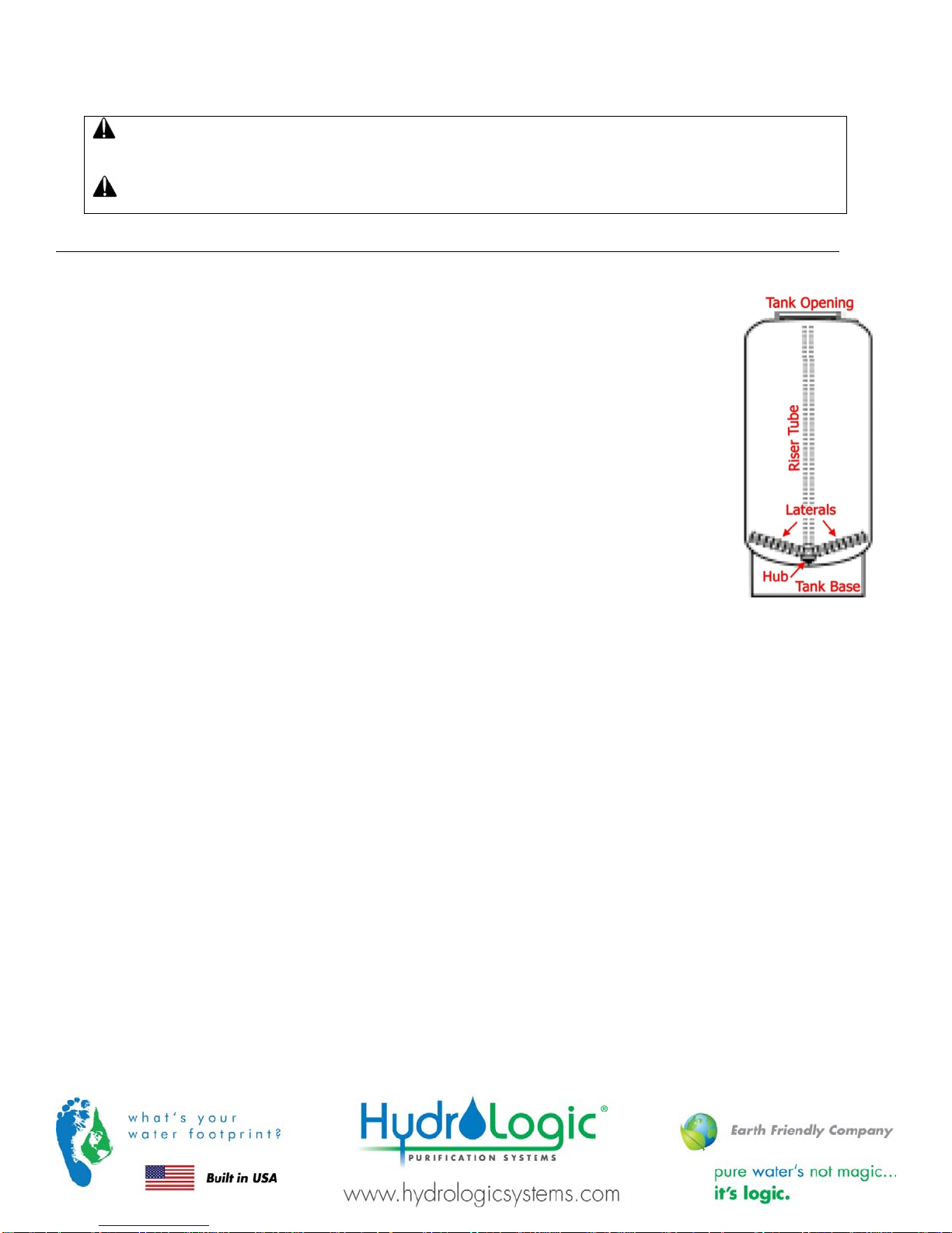
1. Place tank on a level, solid surface in the correct position for installation. Lift the riser tube from
the tank, keeping the attached hub within the opening of the tank. Within the tank, assemble the
laterals onto the hub, twisting each lateral into the hub to lock securely. Gently lower the
assembly to the bottom of the tank. The top of the riser tube should be about level with the top of
the tank.
2. The „riser tube‰ inside the media/resin tank delivers treated water to your control valve. It will
need to be temporarily covered with tape on the top end to prevent anything from falling down
inside the tube during loading.
3. Step back and look at the tank to make sure it is standing straight, and not tilted. The black base
on the bottom of the tank should also be straightened before filling the tank. If your tank is tilted,
simply pick up the tank 2-3 inches off the floor and drop it gently (but firmly) down, favoring the
side of the base that needs to be adjusted.
4. Before loading the media, fill the tank with 2-3 feet of water (or 1/3 full, depending on the tank
size), to soften the fall of the rocks and prevent damage to the distributor. To load the media, use
a funnel in the top of the media tank with the riser tube still inside. Make sure the riser tube is
covered with tape to keep media out.
5. Scoop the media into the funnel, slowly letting it fall down inside the media tank around the riser tube. Fill the tank with the
w
media provided, pouring the media in the following order (1st
of the tank, etc.).
Note: The tank will be approximately - ⅔ full after loading is complete.
ill end up on the bottom of the tank, last will end up at the top
Refer to „Table 2 Resin Quantities per Model‰ for the proper quantities of each component.
I. Gravel YMGRVL11618 0.5 CF (50 lbs) per bag
II. Manganese Greensand YMMNGS 1 CF (85 lbs) per bag
6. Remove the funnel from the top of the tank, and the tape from the end of the riser tube. Brush any loose media off the top
opening of the tank.
7. The bottom of the control valve has an opening with O-rings inside; lubricate the O-ring with a non-petroleum based lubricant.
Position the valve over the top of the media tank, making sure the top of the riser tube inserts inside the opening in the bottom
of the valve.
8. Screw the valve down into the media tank. Another person should hold the tank as the valve is being snugly tightened onto the
tank. Do not over-tighten. Tighten until snug, tighten a bit more, then STOP. The large o-ring will seal itself.
Page 7
Installation and Service Manual – Manganese Greensand Iron Filter
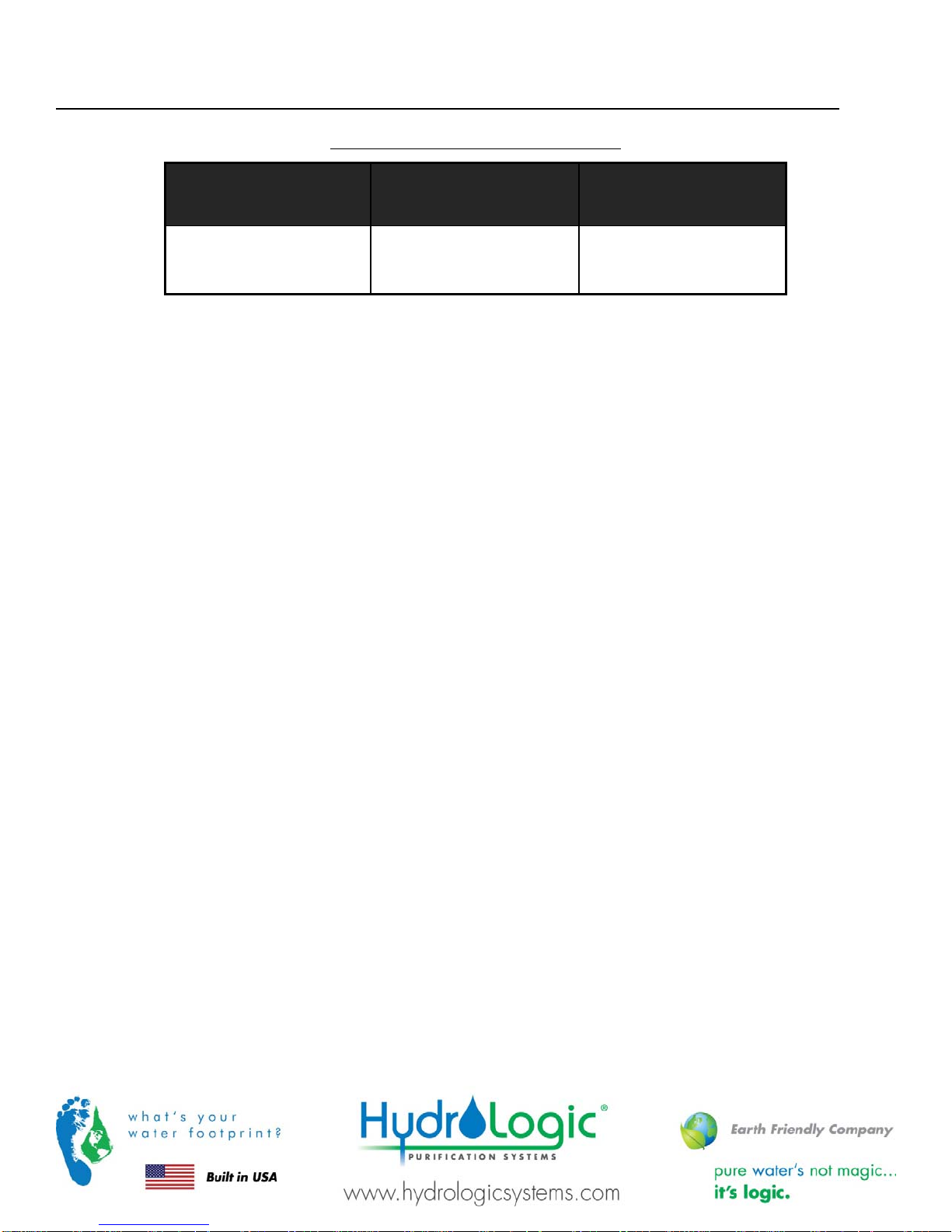
Media Quantity per Model
Table 2 Media Quantity per Model
Model No.*
(-US or EU)
Gravel
1
/16 x ⅛
I
Manganese
Greensand
II
W-MFI1665GET 0.5 CF (50 lbs) 3.5 CF (298 lbs)
Installation and Service Manual – Manganese Greensand Iron Filter
Plumbing
Note:
Caution:
All plumbing is to be done in accordance with state and local codes.
Before placing wall anchors to support piping ensure that no electrical conduit or wiring is located behind the
intended mounting location.
Note:
The control valve, fittings and/or bypass are designed to accommodate minor plumbing misalignments but are not
designed to support the weight of a system or the plumbing.
1. Install connecting piping between raw water source and input pipe on
control valve.
The installation fittings connect to the control valve or the bypass valve
using nuts that only require hand tightening. Do not use a pipe wrench to
tighten nuts on installation fittings. The split ring design, incorporated into
the installation fittings allows approximately 2 degrees off axis alignment
to the plumbing system. The installation fittings are designed to
accommodate minor plumbing misalignments but are not designed to
support the weight of a system or the plumbing.
When assembling the installation fitting package, connect the fitting to
the plumbing system first and then attach the nut, split ring and o-ring.
Heat from soldering or solvent cements may damage the nut, split ring or
o-ring. Solder joints should be cool and solvent cements should be set
before installing the nut, split ring and o-ring. Avoid getting primer and
solvent cement on any part of the orings, split rings, bypass valve or
control valve. Solvent cements and primers should be used in accordance
with the manufacturerÊs instructions.
Slip the nut onto the fitting first, then the split ring second and the o-ring last. Hand tighten the nut. If the fitting is leaking
tightening the nut will not stop the leak. Remove the nut, remove the fitting, and check for damage or misalignment of the oring.
Do not use pipe dope or other sealant on threads. Use teflon tape on threaded inlet, outlet and drain fittings. Teflon tape is
not necessary on the nut connection or caps because of o-ring seals.
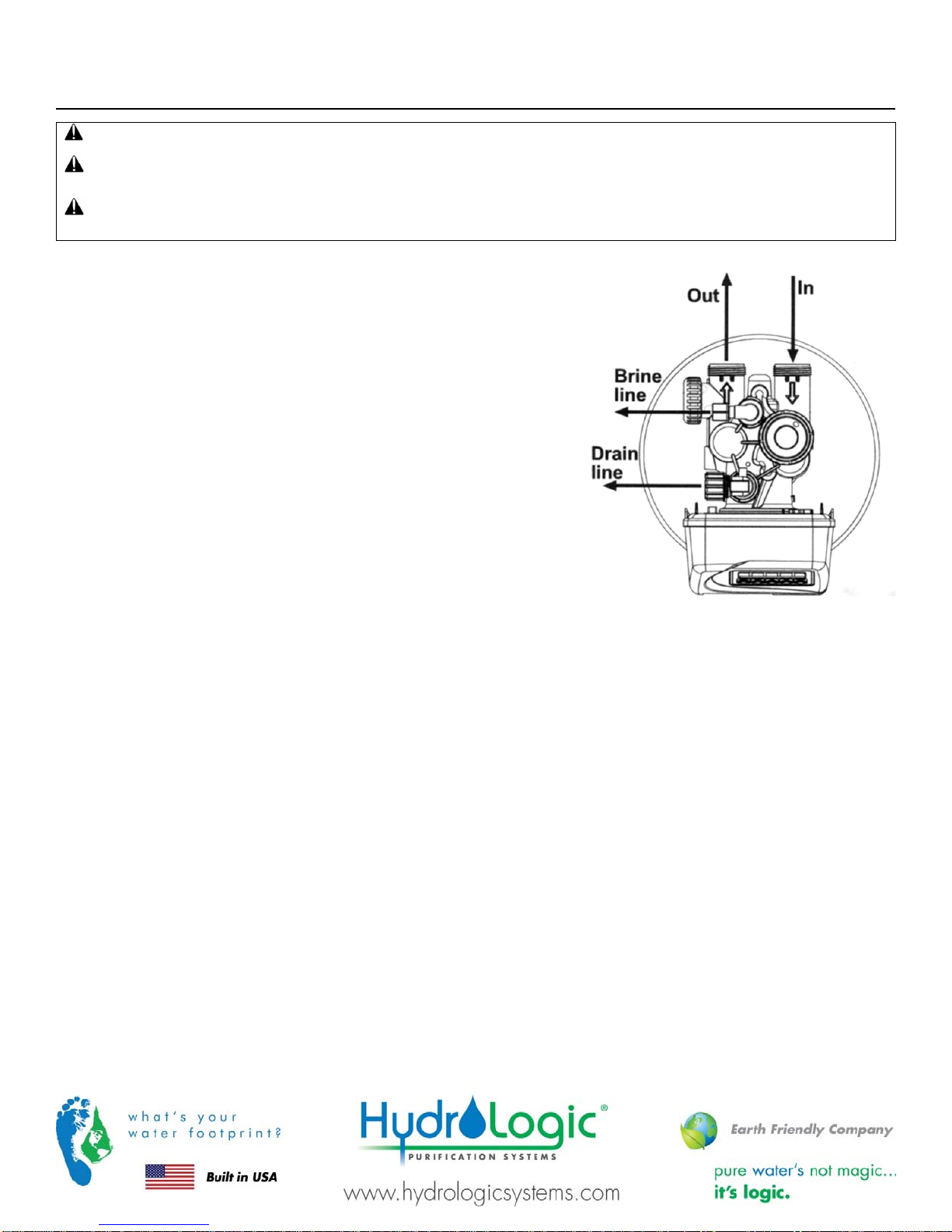
2. Install drain line from control valve to a free flowing drain.
If the drain line is a ⅝‰ flexible polytube, slide the nut onto the polytube, then place the polytube insert into the end of the
polytube and tighten the nut on to the ‰ drain line fitting. The nut is only designed for use with fexible polytube. Use other
nuts if attaching different materials. (To access the drain line flow control, remove the locking clip by pulling it straight out.
Pull fitting out and replace the locking clip so that it is not misplaced. The drain line fitting is pressed in and has an o-ring
seal.)
3.
4. Install piping between valve output and point of use. The installation fittings connect to the control valve or the bypass valve
using nuts that only require hand tightening.
See step 1 for handling details.
Page 9

Installation and Service Manual – Manganese Greensand Iron Filter
Initial Start-Up
For detailed programming and operating information, please refer to the control valve section of this manual.
1. Check all piping connections and make sure feed valves are open. Inspect plumbing for leaks.
2. Check that control valve is connected to electrical source.
3. Open Raw Water source valve.
Note:
4. Fully open a cold water faucet downstream of the system. Allow water to run until clear. Close the cold water faucet.
5. Turn off the supply water.
6. Initiate manual regeneration of the control valve to regenerate: simultaneously press and for three seconds. Press the
button to advance the unit into the backwash cycle. Wait until the motor stops and the backwash time begins to count
down.
7. Open the inlet water supply valve very slowly, allowing the water to fill the tank in order to expel air.
Check for leaks throughout system as pressure is applied.
Note:
For detailed information on the control valve operation, see the valve manual enclosed.
Caution:
8. When water is flowing steadily to the drain without the presence of air, press the button again to advance the When
water is flowing steadily to the drain without the presence of air, fully open the water supply inlet valve.
Press the REGEN button again to advance to the rinse position and allow the water to run to drain for 2-3 minutes or until
the drain runs clear.
9. Press the REGEN button to advance to the service position.
10. Review the control valve operations section of this manual and ensure settings are properly programmed before placing
the filter in service.
11. Review the potassium permanganate feed injection system (supplied separately) to ensure proper configuration and
dosing. *
*
ADDITIONAL EQUIPMENT REQUIRED FOR PROPER OPERATION: Manganese greensand filters require KMn04
(Potassium Permanganate) to be injected into the feed water stream in order to regenerate the media bed. This is usually
done with the use of a chemical injection system including a chemical tank, mixer and metering pump. This equipment is
sold separately and should be designed and sized for each specific installation. The injection method and concentration of
potassium permanganate required depends on the concentration of iron and manganese in the water as well as other
factors. Please contact Applied Membranes, Inc. for assistance in sizing and purchasing the appropriate chemical injection
system.
If water flows too rapidly, there will be a loss of media out the drain.

Installation and Service Manual – Manganese Greensand Iron Filter
Page 11

Installation and Service Manual – Manganese Greensand Iron Filter
System Monitoring and Record Keeping
Monitor the filter daily and record all pertinent data. This data is needed to determine operating efficiency and for performing
system maintenance.
Note:
The latter includes changing of the media, pressure drop across the mineral tank and control valve.
Warranty Claims cannot be processed without adequate operating data and the filter history.
Operating Conditions
For optimum filter performance, observe the following:
Maintain a minimum of 25 psi during backwash cycle.
Water pressure should not exceed 120 psi across mineral tank.
Water temperature should not exceed 110 F.
CAUTION:
rings or plastic components. Exposure to such hydrocarbons may cause the products to leak. Do not use the
product(s) contained in this document on water supplies that contain hydrocarbons such as kerosene, benzene,
gasoline, etc.
Hydrocarbons such as kerosene, benzene, gasoline, etc., may damage products that contain o-
Operating DoÊs and DonÊts
DO:
Monitor system and keep a daily log.
Maintain proper water pressure for backwashing.
DONÊT:
Permit oils or fats in feed water.
Shut down system for extended periods.
Exceed operating pressures or temperatures.
Backwash filter with insufficient water flow.

Installation and Service Manual – Manganese Greensand Iron Filter
Maintenance
Removal & Replacement of Media
Tools Needed:
Wrench (to removing piping)
Screwdriver wide blade
1. Turn off water to filter.
2. Relieve pressure in tank by either opening a downstream valve or cycling the control valve into the back wash position.
3. If a by-pass valve is installed, place it in the by-pass position.
4. Disconnect drain line.
5. Turn off electrical source and disconnect control valve. Remove any wiring connected to control valve.
6. Loosen plumbing from control valve.
7. Carefully move the filter forward until it clears plumbing.
8. Move the filter to an area where access is available to all sides.
Buckets (for materials)
Wet and Dry Vacuum Cleaner or Tarp
9. Carefully loosen control valve on mineral tank top. Slowly unscrew valve being careful not to damage threads in top of
tank.
10. When valve is loose from top of tank, slowly twist it back and forth to remove it from top of distributor tube inside tank.
11. To remove the filter from mineral tank choose one of the recommended methods below:
a. Vacuum Removal: Vacuum all material out of tank and then wash inside with clean water.
b. Manual Removal: Place a canvas on floor to catch media and other materials dumped from mineral tank. Lay
tank on its side and tip it up to dump media and other materials out of tank. Slowly rotate tank as it is being
dumped. When all material is out of tank wash it with clean water.
Note:
Dispose of the media & underbedding by local procedures or laws.
12. Replace media as per media loading instructions.
13. Perform start-up procedure.
Page 13

Installation and Service Manual – Manganese Greensand Iron Filter
Control Valve Operation & Service
CV1 Control Valves
Control Valve Specifications
Minimum/Maximum Operating Pressures: 20 psi (138 kPa, 1.4 bar) to 125 psi (862 kPa, 8.6 bar)
Minimum/Maximum Operating Temperatures: 40F (4C) to 110F (43C)
No user serviceable parts are on the PC board, the motor, or the power adapter. The means of disconnection from the main
power supply is by unplugging the power adapter from the wall.

Installation and Service Manual – Manganese Greensand Iron Filter
Panel Operation Quick Reference Guide
Manual Regeneration (Backwash)
Note: If you need to initiate a manual regeneration, either
immediately, or tonight at the preprogrammed time (typically 2
a.m.), complete the following steps.
For Immediate Regeneration: For Regeneration Tonight:
Press and hold and simultaneously until valve
motor starts (typically 3 seconds).
Error Message
If the display shows „E1‰, „E2‰, „E3‰, or „E4‰ (for error), check
the trouble shooting section to identify the error.
General Operation
Arrow will point to Regen if a regeneration is expected „Tonight‰.
When the system is operating one of two
displays will be shown: time of day or days
until the next regeneration.
Pressing or button will toggle between the
two choices.
To Set Time of Day
In the event of a prolonged power
outage, time of day flashes,
indicating that it needs to be reset. All
other information will be stored in
memory no matter how long the
power outage. Please complete the
steps as shown to the right. To access
this mode, press „SET‰.
Arrow will point to Regen if a regeneration is expected „Tonight‰.
Press and release and simultaneously
(notice that arrow points to Regen).
5. Accessed by pressing SET for approximately 3
seconds.
6. Adjust hour with or . With 60 Hz line frequency
detection on power-up, timekeeping is 12 hour with
PM indicator. With 50 Hz line frequency detection
on power-up, timekeeping is 24 hour without the PM
indicator. Press SET to go to the next step.
7. Adjust minutes with or .
8. Press SET to complete and return to normal operation.
Page 15

Installation and Service Manual – Manganese Greensand Iron Filter
To Set Time of Regeneration and Days
Between Regeneration
For initial set-up or to make adjustments,
please complete the steps as shown.
Access this mode by pressing SET and for
approximately 3 seconds. The number of days
between regenerations may need to be varied
based on usage and water conditions.
(This step will not appear if the 7-day clock
option is selected.)
6. Accessed by pressing SET and simultaneously for
about 3 seconds.
7. Set Regeneration Time Hour. Set the time for
regeneration to start. Press SET to go to the next step.
8. Set Regeneration Time Minutes. Press SET to go to the
next step.
9. Set number of Days between regeneration cycles.
10. Press SET to complete and return to normal operation.
 Loading...