

Hydrolevel Company AcuTemp, AcuTemp 2000, AcuTemp 2000-135 Installation Instructions And Operating Manual
Installation Instructions
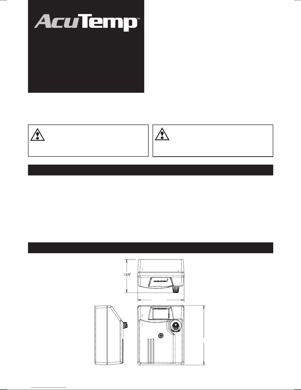
3-17/32"
and Operating Manual
The AcuTemp utilizes a microcontroller-based
Temperature
Control
NOTICE - Read these instructions completely before proceeding
with the installation. Retain these instructions for future reference.
design to control water temperature. An advanced
software algorithm closely monitors the rate of
tank temperature changes and controls the heating
source to minimize fluctuations in tank temperature
while optimizing fuel efficiency. The control features
adjustable temperature settings for both residential
and commercial temperature operating ranges.
Electrical shock
WARNING
electrical shock, death, or equipment damage, disconnect power supply before installing or servicing control.
hazard. To prevent
RATINGS
Input 24 VAC, 60 Hz
Power 2.4 VA
Output Dry contacts, 50 VA
@ 24 VAC, 60 Hz
Ambient temp 30°F - 140°F
Operating temp (user selected)
Differential Automatically controlled 5°F - 10°F
DIMENSIONS
All work must be
WARNING
qualified and licensed professional in accordance with
all applicable codes and ordinances.
Model 2000 (Residential Setting): 60°F - 160°F default
Model 2000 (Commercial Setting): 60°F - 180°F
Other Models: 60°F to the number specified in the suffix of the
model number. (ex Model 2000-135 has an operating temp
range of 60°F - 135°F)
performed by a
2-3/4"
1
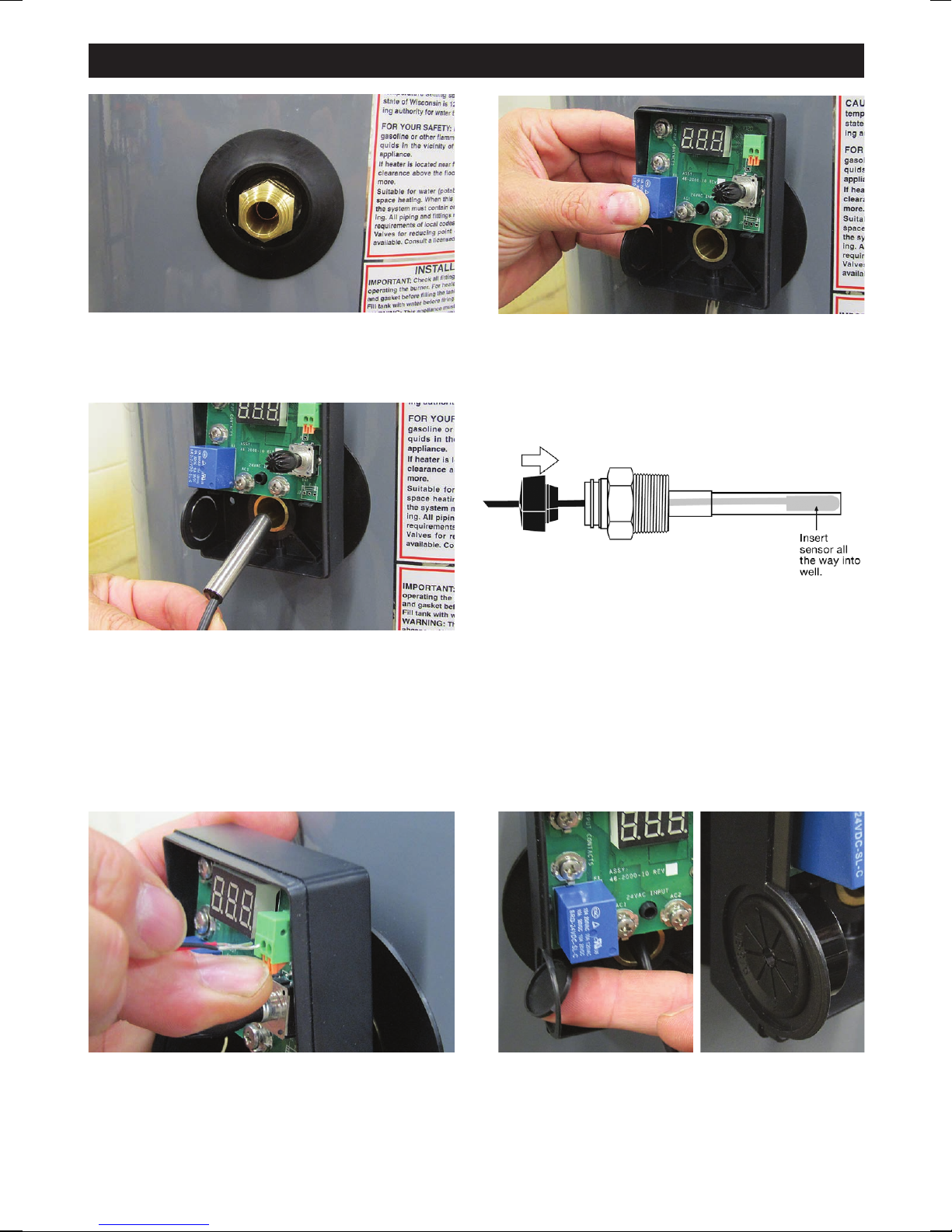
INSTALLING THE CONTROL
1 Locate the immersion well in the tank that is
designed for the temperature control.
2 Hold the AcuTemp control onto the well and
tighten the screw at the base of the control.
3A Sensor and Well
(remote mounted control)
3 Slide the sensor into the well. NOTE: two
sensor diameters (3/8" & 1/4") are available to
accommodate different well sizes.
WARNING: The sensor must be fully inserted and fit snugly in the well for proper operation.
If a smaller sensor is used or the sensor is not fully inserted overheating and scalding could result.
1. Insert the sensor all the way into the well.
2. Install the rubber well cap onto the sensor wire
and slide to cover the end of the well
4 Trim the sensor wire to the required length (if
needed). Plug the sensor wire into the sensor
input. The terminals are not polarity sensitive.
NOTE: Be sure the wires are fully inserted into the
sensor input.
5 Remove the knockout and replace it with the
plastic bushing.
NOTE: For line voltage applications replace the
knockout with proper conduit in accordance with
all applicable codes and ordinances.
2
 Loading...