

Hydrolevel Company 3200-Plus User Manual
MODEL 3200-Plus
INSTALLATION INSTRUCTIONS
and OPERATING MANUAL
Temp Limit / LWCO Control
with Thermal Targeting
™
for Water Boilers
120 VAC Input / 24 VAC Burner Circuit
PATENT NO. 7,891,572
• Saves Fuel – Features Thermal Targeting™ technology and
• Outdoor Reset Ready – Provides Outdoor Reset and Warm Weather
• Universal Design – Replaces common cold-start and triple-action
• Operating Indicators – LEDs, Dynamic Display and Test Button provide
• Prioritizes Domestic Hot Water – Gives priority to low limit setting or to
• Reduces Condensation – Holds circulator off until boiler reaches 125°F
•
Three Function
Design
Temperature Limit Control
Designed for cold start and tankless
coil boilers.
Low Water Cut-Off
Provides protection against potentially
dangerous low water conditions
when installed with the Hydrolevel
Electro-Well™ (see page 2 for details).
Thermal Pre-Purge capability
Shut-Down capability with the addition of Hydrolevel OS-100 Outdoor
Sensor Kit (sold separately)
Aquastats*
continual and on-demand status checks
calls from indirect water heater
*Aquastat is a registered trademark of Honeywell International, Inc.
Boiler Reset Control
Thermal Targeting – On-board micro-
•
processor adjusts boiler temperature
based on heating demand.
Outdoor Reset Ready – Compatible with
•
Hydrolevel OS-100 Outdoor Sensor Kit
(sold separately) for outdoor reset and
warm weather shut-down functionality.
WARNING
installing or servicing control. Only qualified personnel may install or service this control in
accordance with local codes and ordinances. Read instructions completely before proceeding.
WARNING
is recommended for unattended dwellings in climates subject to sustain below-freezing temperatures.
Electrical shock hazard. To prevent electrical shock, death or
equipment damage, disconnect power supply before
Frozen pipes/water damage. Central heating systems are prone to shut down as a result of power or fuel outages,
safety related fault conditions or equipment failure. Installation of freeze protection monitoring or other precautions
83 Water Street • New Haven, CT 06511 • Phone (203) 776-0473 • FAX (203) 773-1019 • www.hydrolevel.com
CAUTION
should be thoroughly cooled before installing or
servicing control.
To prevent serious
burns, boiler
1
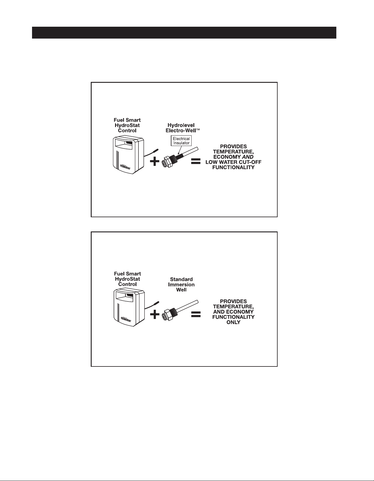
IMMERSION WELLS
Fuel Smart HydroStat can be installed on an existing immersion well already in the boiler or on a Hydrolevel Electro-Well™
(sold separately). The low water cut-off function is automatically activated when installed on an Electro-Well™.
IMPORTANT: The control will not provide low water cut-off protection when installed on a standard immersion well.
NOTE: Do not use heat-conducting grease.
Fuel Smart HydroStat installed
with Hydrolevel Electro-Well™
IMPORTANT: For proper operation of the low water cut-off
function, there must be a minimum of ½" clearance between
the copper well tube and any surface within the boiler.
See Electro-Well models on page 15.
Fuel Smart HydroStat installed
with standard immersion well
NOTE: When installed on a standard immersion well, the
“LWCO Active” LED will not illuminate.
2
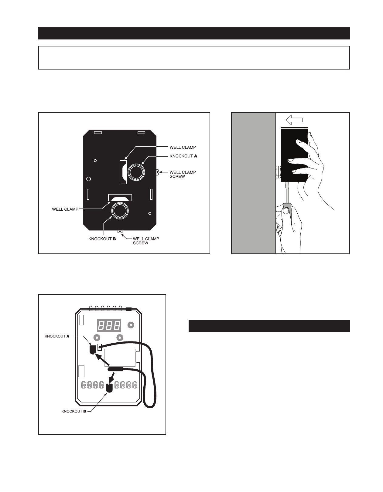
MOUNTING THE CONTROL
IMPORTANT Make sure that the immersion well or Electro-Well™ is installed in the boiler manufacturer’s designated
temperature limit control tapping.
NNOOTTEE::
If
installing an Electro-Well, pipe sealing compound should be used. Teflon tape is not recommended.
STEP 1
back of the control (Fig. 1). Select which of the two positions
(2 knockouts) is best for the location of the control. Remove the
knockout.
FIG. 1
Two mounting positions are available on the
BACK OF FUEL SMART HYDROSTAT BOX
STEP 2 Place control on the well. While
holding box against well nut, tighten well clamp
screw. (Fig. 2)
FIG. 2
STEP 3 Insert sensor ALL THE WAY into well
through the knockout (A or B) you have chosen.
(Fig. 3)
FIG. 3
NOTE: In the case of space restrictions, the Fuel Smart HydroStat
control may be mounted in a horizontal orientation without any loss
of function. Hydrolevel recommends vertical mounting, when possible, for proper orientation of LED display.
REMOTE MOUNTING KITS
Remote Mounting Kits are available separately for mounting the
Fuel Smart HydroStat control box in a remote location. Each kit
includes mounting hardware and a remote sensor.
Part No. Description
48-101 HydroStat Remote Mount Kit with 24" sensor
48-102 HydroStat Remote Mount Kit with 48" sensor
48-103 HydroStat Remote Mount Kit with 10' sensor
48-104 HydroStat Remote Mount Kit with 20' sensor
48-121 HydroStat Pipe Mounting Kit with 48" sensor
3
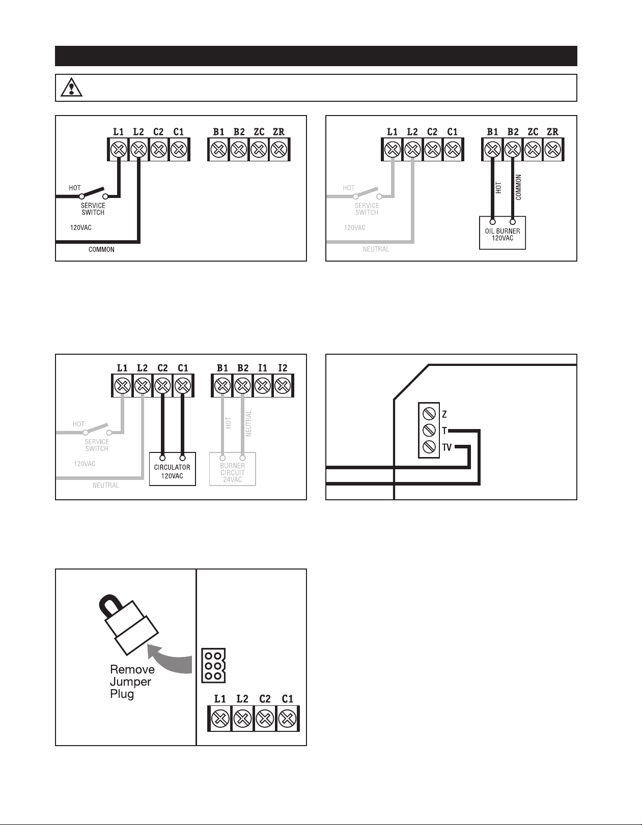
WIRING
WARNING
Electrical shock hazard. To prevent electrical shock, death or equipment damage, disconnect power supply before
installing or servicing this control.
STEP 1
Connect 120 VAC Hot to terminal L1. Connect 120 VAC
Common to terminal L2. Disconnect means and overload
protection as required (provided by others).
STEP 2
Connect the burner circuit to B1-B2. (B2 is common.)
STEP 3
Connect the circulator to C1-C2. (C2 is common.)
STEP 4
Connect the thermostat to T-TV.
STEP 5
If the boiler is equipped with a plug-in style vent damper,
unplug the factory installed jumper from the receptacle on the
circuit board and replace it with the vent damper plug.
NOTE: Once a vent damper plug is connected to the
HydroStat, the control is permanently altered and will no
longer function when the vent damper plug is disconnected
4
.

WIRING continued
WARNING
Electrical shock hazard. To prevent electrical shock, death or equipment damage, disconnect power supply before
installing or servicing this control.
STEP 6 For Systems with Indirect Water Heaters
When installing with an indirect water heater, the signal from the indirect must be separated from the heating zone signals and
wired to I1 and I2 as shown above. Calls to I1 and I2 will bypass the Thermal Targeting feature and allow the boiler to fire to
the high limit setting to heat the indirect tank.
NOTE: If you choose not to separate the indirect signal from the heating zones, the Economy Feature should the turned OFF
to insure that the boiler supplies adequate temperature to heat the indirect tank (see page 6).
ZONE VALVE WIRING
IMPORTANT: Use a separate transformer to power zone valves. Connecting zone valves to Z-TV may overload the
HydroStat and cause a lock-out condition (see
the burner circuit, vent damper, and Z-TV connections must not exceed 1.2 amps (30 VA). Connect zone valve end-switch
to T-TV as shown below.
Troubleshooting
on page 12 for more information). The total load, including
5
 Loading...