

Page 1
Automatically shuts off burner, after delay, in a low water
condition to prevent dry firing.
CG470 Series
Low Water Cut-Offs
For Steam Boilers
120 VAC Operating Voltage
Max. Pressure 15 psi
U.S. Patent Nos. 5,739,504 & 6,390,027
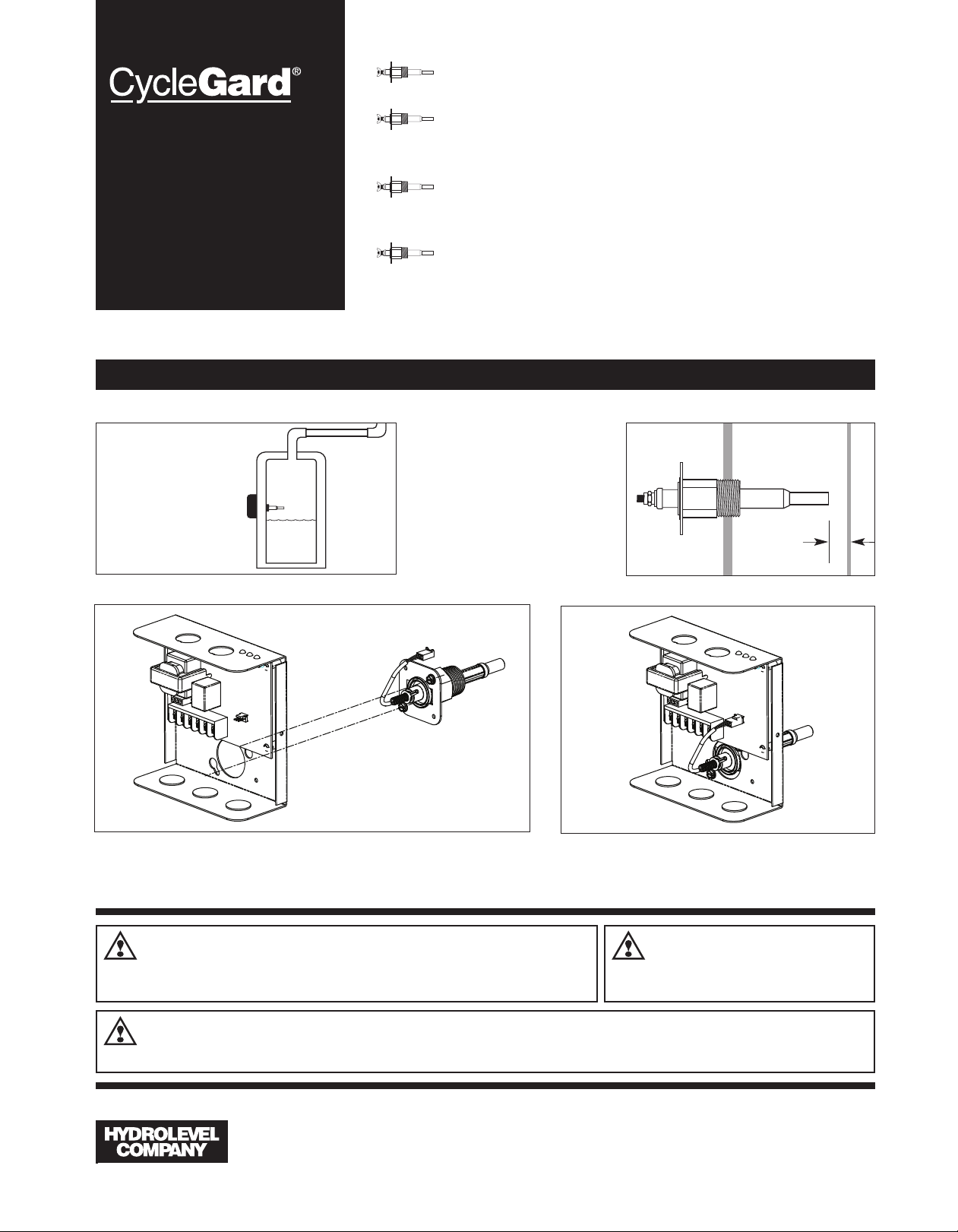
MOUNTING THE CONTROL
The probe may be
installed in the boiler
above the lowest safe
water level established by
the boiler manufacturer.
Most manufacturers provide a suitable tapping in
the side of the boiler.
SAFE
WATER
LINE
Enhanced Intermittent Level Test technology – active only
when water is at boiling temperature. Provides added protection in foaming and volatile water conditions.
Time delay sequencing prevents burner short-cycling caused
by momentary dips in water level and allows a water feeder
to replenish water to a level above the probe.
Integral temperature sensor provides High Limit Lock-Out
feature for an unprecedented level of boiler protection.
STEP 1 Screw the probe
into the LWCO tapping in the boiler. Allow 1/4" clearance from the
probe to any boiler surface, tube
or baffle. NOTE: Excessive use of
Teflon tape to seal probe piping
threads may insulate the control
from boiler ground. This could
result in the control not operating.
1/4"
STEP 2 Loosen the two control cover screws and remove the cover.
Assemble the chassis to the probe flange and secure with the screws provided.
WARNING
installing or servicing control. Only qualified personnel may install or service this control in
accordance with local codes and ordinances. Read instructions completely before proceeding.
WARNING
is recommended for unattended dwellings in climates subject to sustain below-freezing temperatures.
Electrical shock hazard. To prevent electrical shock, death or
equipment damage, disconnect power supply before
Frozen pipes/water damage. Central heating systems are prone to shut down as a result of power or fuel outages,
safety related fault conditions or equipment failure. Installation of freeze protection monitoring or other precautions
83 Water Street • New Haven, CT 06511 • Phone (203) 776-0473 • FAX (203) 773-1019 • www.hydrolevel.com
STEP 3 Plug the wire lead from the probe into the
mating connection on the circuit board.
1
CAUTION
should be thoroughly cooled before installing or
servicing control.
To prevent serious
burns, boiler
Page 2
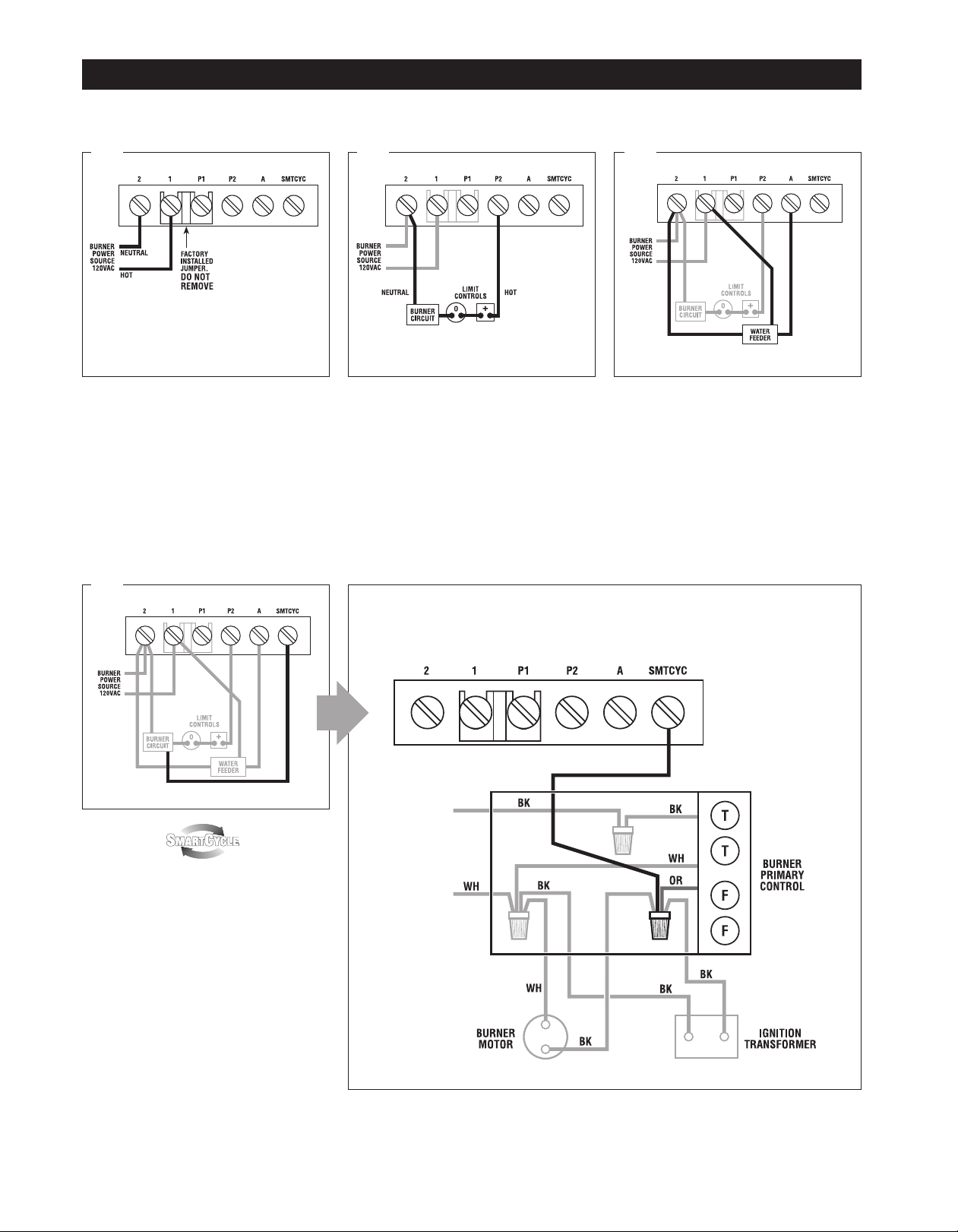
WIRING – Model CG470
1 2 3
Connect input voltage (120 VAC, 60 HZ) to
terminals 1 and 2.
4
Connect terminal 2 to burner circuit neutral.
Connect terminal P2 to burner Circuit in
series with other limit controls. Consult boiler manufacturer instructions for proper terminal connections. Control should be wired
in series with and before other limit controls.
Detail of SmartCycle Connection
Model CG470
Optional water feeder connection.
Connect feeder N to terminal 2. Connect Feeder
H to terminal 1. Connect feeder “FEED” or “W”
to terminal A. For water feeders with 2 leads,
connect feeder neutral to terminal 2 and feeder
hot to terminal A.
NOTE: Use of a solenoid valve or McDonnell &
Miller Model 101A water feeder may cause
flooding and is not recommended for use with
this low water cut-off.
OPTIONAL ACTIVATION
Connect “SMTCYC” terminal on the
CycleGard control to the orange burner wire
(120VAC) located under the primary. See
detail illustration at the right.
See SmartCycle description on next page.
2
Page 3

Enhanced Intermittent
Level Test Feature
To provide added protection to today’s smaller boilers, CycleGard Model CG470 is
equipped with an enhanced Intermittent Level
Test (ILT) feature. Fifteen minutes after the
boiler reaches boiling temperature, the ILT
feature removes power from the burner for
60 seconds. During this ILT test, foam dissipates and the water level quickly stabilizes,
allowing the CG470 to monitor the true water
level in the boiler. If the water in the boiler is
at a safe level, the control will re-energize the
burner. If the water level has dropped to a
level below the probe, the control will keep
the burner off (and send power to an optional
water feeder) until the water level is replenished. The 60 second ILT test will repeat
every 15 minutes as long as the boiler
remains at boiling temperature. The ILT feature disengages when the boiler temperature
is below the boiling point.
OPERATING INSTRUCTIONS
The optional Smart Cycle feature is designed to
prevent unnecessary ILT tests in the event the
burner cycles off for other reasons (ex. pressure limit or thermostat calls). When activated
(see wiring on previous page), the Smart Cycle
feature restarts the 15 minute timing sequence
each time the burner fires. So, for example, if
the pressure control shuts down the burner,
the Smart Cycle feature will reset the 15
minute clock once the pressure control reenergizes the burner. This prevents an ILT
from occurring sooner than is needed as the
control was able to monitor the settled water
level during the pressure limit interruption.
Hi Temp Lock-Out
Unlike any other steam low water cut-off, the
CG470 monitors boiler temperature in addition to water level. This feature will shut
down and lock out the burner circuit if the
boiler reaches an unsafe level (250°F).
NOTE: For proper low water cut-off operation, the boiler should be cleaned at initial installation and periodically thereafter. Refer to the boiler
manufacturer’s instructions for cleaning procedures.
OPERATING TEST PROCEDURE
1. After installation, bring the boiler water to
a safe operating level, turn on power and
set the thermostat to call for heat. The
amber LED lamp should be off. The boiler
will fire immediately.
2. Slowl
y lower the boiler water to a point
below the probe. The amber LED lamp on
the control will light. The lamp may begin
to flicker with the bouncing water level.
Stop draining the boiler when the lamp
glows steadily. NOTE: The water should
not be lowered beyond a visible point in
the gauge glass.
3. The boiler will shut down within 15
seconds.
TEST BUTTON
The CG470 is equipped with a button to test
wiring and control operation. To use the test
button, remove the cover and press the button located on the circuit board. The burner
will shut off for the length of time the button
is pressed. If the burner does not shut off,
remove power and recheck wiring. Note:
Hydrolevel recommends lowering the water
level (as described in “Operating Test
Procedure”) to functionally test the control
and probe operation on an annual basis.
IF BURNER DOES NOT SHUT DOWN IN
LOW WATER
1. Check terminal block wiring to insure that
all connections are correct.
2. Check the probe installation to insure that
there is 1/4" clearance from any surface
within the boiler or pipe. (Refer to Step 1
on page 1 of this instruction sheet.
3. Clean the boiler in accordance with the
manufacturer’s instructions. Machining
oils, grease, rust and other contaminants
in the boiler water can cause foaming or
surging and make a low water condition
difficult to detect during burner operation.
IF THE AMBER LED LAMP IS ON
The amber LED lamp indicates that the water
is below the probe. If the gauge glass shows
that the water is at the correct operating level
and the amber LED is lit, check the following:
1. Check for plugged gauge glass.
2. Make sure probe lead wire is properly
secured to the terminal.
3. Check for proper ground between probe
and boiler shell. Excessive use of Teflon
tape or sealing compound may isolate the
probe from the boiler shell.
4. Remove probe and examine for oily
residue. Clean probe with steel wool and
skim boiler.
IF THE RED LED LAMP IS ON
The red LED lamp indicates that the boiler
has experienced an unsafe temperature
(250°F). The control will lock out the burner
circuit and illuminate the LED when this
occurs. DANGER: Adding water to an overheated boiler can cause an explosion. The
boiler must be allowed to fully cool before
adding water. The boiler should be evaluated
by a qualified service technician before
restoring operation. The CycleGard control
should be replaced.
IF THE RED LED LAMP IS BLINKING
A blinking red LED lamp indicates that the
control has been locked out on an unsafe
temperature at some point in its history. The
CycleGard control should be replaced.
IF THE GREEN LED LAMP IS ON
The green LED lamp indicates that the control
is conducting an Intermittent Level Test. The
burner does not fire during the test period.
See Intermittent Level Test Feature on this
page for more details.
3
Page 4

MAINTENANCE
To ensure optimum performance remove and inspect probe annually. Clean any sediment or scale from the probe using a scouring pad or steel
wool. Re-install the probe and perform the Operating Test Procedure described on page 3.
PROBES
EL1230 – STANDARD MODEL – 3/4" NPT EL1232-P – 3/4" NPT
The Probe Makes the Difference The probe used in all Hydrolevel controls offers you distinctive advantages. Unlike float
devices, there are no moving parts to wear stick, or “hang-up” the in harsh boiler environment. A stuck or “hung-up” float can cause dangerous
low water conditions. And if suddenly released, a float can feed cold water into overheated tubes or plates and cause explosive results. The
Hydrolevel control has no float bowl so sediment cannot collect. The reliable microprocessor-based design and low maintenance probe are
designed to provide years of troublefree operation.
DIMENSIONS SPECIFICATIONS
MAXIMUM PRESSURE: 15 PSI
INPUT VOLTAGE: 120 VAC, 60 HZ
SWITCH RATINGS: 5.8 FLA, 34.8 LRA
SWITCH CONTACTS: SPDT
LIMITED MANUFACTURERʼS WARRANTY
We warrant products manufactured by Hydrolevel Company to be free from defects in
material and workmanship for a period of two years from the date of manufacture or
one year from the date of installation, whichever occurs first. In the event of any claim
under this warranty or otherwise with respect to our products which is made within
such period, we will, at our option, repair or replace such products or refund the purchase price paid to us by you for such products. In no event shall Hydrolevel
ALARM CIRCUIT: 125 VA @ 120 VAC
Company be liable for any other loss or damage, whether direct, indirect, incidental or
consequential. This warranty is your EXCLUSIVE remedy and shall be IN PLACE OF
any other warranty or guarantee, express or implied, including, without limitation, any
warranty of MERCHANTABILITY or fitness for a particular purpose. This warranty
may not be assigned or transferred and any unauthorized transfer or assignment
thereof shall be void and of no force or effect.
Pilot Duty
83 Water Street • New Haven, CT 06511 • Phone (203) 776-0473 • FAX (203) 773-1019 • www.hydrolevel.com
4
CG470-1012
 Loading...