

Page 1
724 Series
Low Water Cut-Off
Feeder Combination
for Steam Boilers
24 VAC Operating Voltage
WARNING: Power must be off during installation or servicing of the control. Only qualified personnel may install or service the
control in accordance with local codes and ordinances. Read instructions completely before proceeding. Caution – Disconnect power
supply before beginning installation to prevent electrical shock or equipment damage.
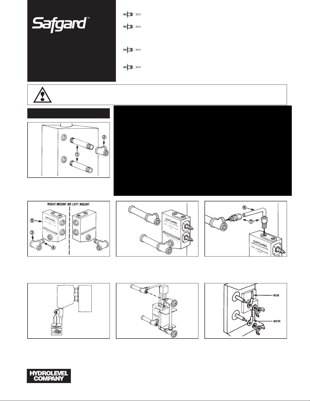
HOW TO INSTALL
1
No moving parts in water.
No floats to hang-up or foul.
Unique two probe design. Bouncing
water line wonʼt cause on-off burner
cycling or water valve slamming
noise.
Easy installation. Quick hook-up
fittings adapt control to all 8" to 14"
sight glasses.
Simple fast wiring. Can be used with
any standard automatic water feeder.
(2) 6" x 1/2" brass nipples
(1) 1/2" x 1/2" x 3/8" tee
(1) 1/2" x 1/2" x 1/2" tee
(1) 2" x 1/2" brass nipple
(1) 711C manifold casting
(1) 3/8" copper tube
(2) 3/8" compression fittings
(1) 3/4" nipple (not included)
(1) Blow down valve
(not included)
Remove gauge glass assembly and nipples replacing nipples with two 6" brass nipples provided.
Install 1/2" x 1/2" x 3/8" teeon top nipple.
2 34
Install 1/2" x 2" brass nippleand 1/2" x 1/2" x
1/2" teeto 1/2" threaded hole in casting.
Note: Casting is designed for either left or right
mounting on gauge glass. Be sure to plug hole on
opposite side.
Thread tee attached to casting into bottom 6" nipple. Tighten until casting is vertical.
Install compression fittingsinto casting and
top tee. Size copper tubingand tighten
between the two compression fittings.
5 67
Attach control to probes using No. 8-32 self tapping screws provided. Install blow down valve (by
others) in bottom 3/4" tapped hole. Be sure to
attach maintenance tag in prominent place near
valve.
83 Water Street • New Haven, CT 06511 • Phone (203) 776-0473 • FAX (203) 773-1019 • www.hydrolevel.com
Reattach gauge glass cocks and gauge glass into
end of 1/2" tees. Pressure-trol can be threaded
into 1/8" threaded hole on top of casting. If pressure-trol is not used, plug 1/8" hole on top of
casting.
Attach blue probe lead wire to upper probe and
white probe lead wire to bottom probe with wing
nuts and lock washers provided.
Page 2
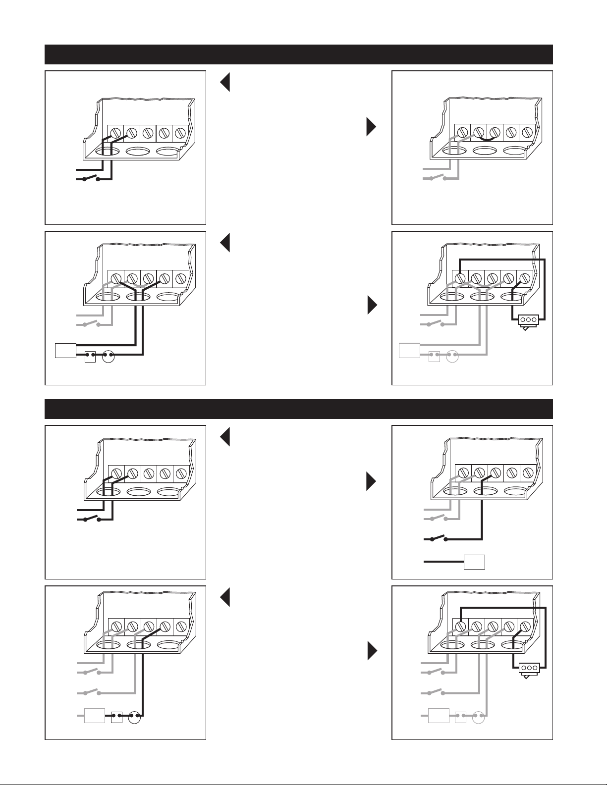
WIRING METHOD A:
s
s
SAME POWER SOURCE FOR CONTROL AND BURNER CIRCUIT.
A1
must be supplied to terminals 1 and 2 for internal
operation of the control.
Install a jumper between terminal 2
and terminal P(1). Power from terminal
P(1) is supplied to terminal P(2) when water
reaches the upper probe. Power to terminal P(2)
is removed when water falls below the bottom
probe.
A3 A4
burner circuit in series with other limit controls.
Consult boiler manufacturer’s instructions for
proper terminal connections. NOTE: Control is
wired in series with and before other limits.
Feeder Connection: Connect feeder
common to terminal 1. Connect feeder
hot to terminal V. Whenever water falls below the
lower probe, power is supplied to the feeder terminal V. When water reaches the upper probe,
power to the feeder is removed.
Connect input voltage (24 VAC, 60HZ)
A1
to terminals 1 and 2. 24 VAC, 60HZ
Connect terminal 1 to burner circuit
A3
neutral. Connect terminal P(2) to
A2
A2
A4
WIRING METHOD B:
B1 B2
B3 B4
SEPARATE POWER SOURCE FOR CONTROL AND BURNER CIRCUIT.
Connect input voltage (24 VAC, 60HZ)
B1
must be supplied to terminals 1 and 2 for internal
operation of the control.
Connect hot lead from burner
control circuit to terminal P(1).
This terminal supplies power to terminal P(2) in
normal operating conditions when water is at the
probe. Connect neutral to burner circuit.
NOTE: Consult boiler manufacturer’s instructions
for proper terminal connections.
Consult boiler manufacturer’s instructions for
proper terminal connections. NOTE: Control is
wired in series with and before other limits.
Feeder Connection: Connect feeder
common to terminal 1. Connect
feeder hot to terminal V. Whenever water falls
below the lower probe, power is supplied to the
feeder terminal V. When water reaches the upper
probe, power to the feeder is removed.
to terminals 1 and 2. 24 VAC, 60HZ
Connect terminal P(2) to burner circuit
B3
in series with other limit controls.
B2
B4
NOTE: All schematic diagrams show all systems in
the off position. No power applied.
Page 3

PRINCIPLE OF OPERATION
The 724 Series low water cut-off is designed to
maintain a safe operating water level in the boiler.
When water is in contact with the upper probe, the
control enables the burner to fire (switch contacts
P – P are closed). When the water level falls below
the lower probe, the control will de-energize the
burner circuit. The control will not re-energize the
burner until the water level is restored to the
upper probe level.
Hydrolevel controls are electronically operated.
Water is used as an electrical conductor to complete a circuit from the probe to the control unit.
The control unit provides switching contacts to
operate the burner circuit and optional water feeder.
The 724WF includes a feed valve designed to
automatically restore the water level in the event
of a low water condition. When water falls below
the lower probe, the 724 will energize the feed
valve (switch contact 2 – V make). When the boil-
INSTALLATION & OPERATION OF FEEDER
A feed valve is supplied standard with control
model 724WF. It is recommended that a shut-off
valve and union be installed on either side of the
water feed valve and a by-pass valve and piping
be installed to permit removal of the water feed
valve should service be required. During normal
operation, by-pass valve should be closed and isolation valves should remain open.
er water level is restored to the upper probe, the
724 will de-energize the feed valve and restore
burner operation. The 724CF does not include a
feed valve, but does provide contacts for operation
of a steam boiler water feeder.
OPERATING INSTRUCTIONS
NOTE: Hydrolevel recommends that the boiler
manufacturer’s procedures for skimming the boiler be performed prior to placing the control into
operation.
After installation, raise the boiler water level
11
until water is in contact with the upper probe.
Turn on power and set the thermostat to call for
heat. The burner should fire immediately.
Using the boiler drain, slowly lower the water
22
level to a point below the lower probe. The
burner should shut down immediately upon a
low water condition.
TROUBLESHOOTING
If the burner does not shut down upon water
11
falling below the lower probe: Remove power to
the burner and check installation. Check wiring
and make sure that burner is connected to the
fourth terminal from left on terminal (P2). If
wiring is correct, check to make sure the
probes are not falsely grounded. Voltage
between the probes and chassis ground should
be 120-140 VAC with water beneath both
probes. A lower reading may indicate a shorted
probe. Remove probes and check for contamination.
If the burner will not fire with water at the top
22
probe: With a voltmeter and power applied at
terminals 1 and 2: Check the voltage between
NOTE: The water should not be lowered beyond
a visible point on the gauge glass.
IMPORTANT: If the burner does not shut down
in a low water condition, turn off power immediately and refer to troubleshooting instructions
below.
the upper probe and chassis ground. Reading
should be 0-10 VAC with water at the upper
probe. A higher reading may be the result of
poorly conductive water or probe contamination. Remove probes and check for contamination. If the burner will still not fire after cleaning
probes, contact factory for assistance.
Page 4
MAINTENANCE
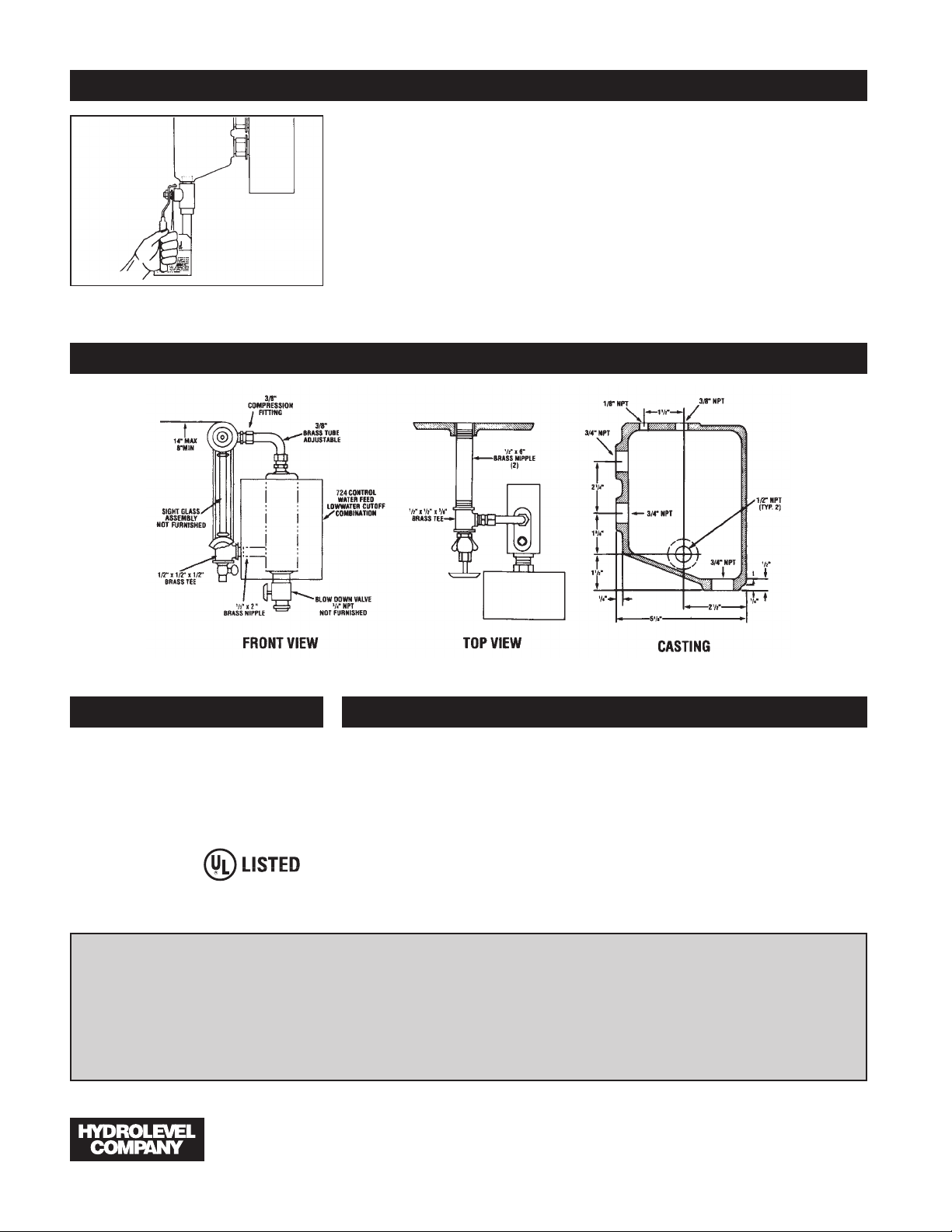
DIMENSIONS
To insure proper operation, the 724 Series Control
requires periodic maintenance. During normal
boiler operation, sediment may accumulate in the
probe housing. If left unchecked, this sediment
can build up and interfere with the operation of
the control. Failure to properly maintain the control can lead to severe damage to the boiler or
other property, personal injury or death.
To flush the sediment from the chamber, the control must be blown down throughout the heating
CAUTION: Protect yourself when blowing down the control.
Hot water and steam will flow out of the control during this process.
season in accordance with the following schedule:
First Week Following Installation: Every Day.
Thereafter: Once a Week.
Instructions: To blow down the control, place a
heat resistant pail directly beneath the control
casting blow down valve. Open the valve and allow
the sediment and water to drain into the pail.
Continue to drain the water until it runs clean. One
to two gallons is generally sufficient.
SPECIFICATIONS
MAXIMUM PRESSURE: 35 PSI
INPUT VOLTAGE: 24 VAC, 60 HZ
SWITCH RATINGS: 5.8 FLA, 34.8 LRA
SWITCH CONTACTS: SPDT
ALARM CIRCUIT: 125 VA @ 120 VAC
Pilot Duty
OPTIONS
The VXT water feeder (available separately) can be
used with Hydrolevel or other low water cut-offs
to automatically replenish boiler water in the event
of a low water condition. The VXT offers programmable feed amount and feed delay settings. These
can easily be set to ensure the proper feed
amount and to provide adequate time for condensate to return to the boiler before starting a feed
cycle. The VXT’s digital feed counter tracks the
amount of water added to the boiler exposing sys-
LIMITED MANUFACTURERʼS WARRANTY
We warrant products manufactured by Hydrolevel Company to be free
from defects in material and workmanship for a period of two years from
the date of manufacture or one year from the date of installation,
whichever occurs first. In the event of any claim under this warranty or
otherwise with respect to our products which is made within such period, we will, at our option, repair or replace such products or refund the
purchase price paid to us by you for such products. In no event shall
83 Water Street • New Haven, CT 06511 • Phone (203) 776-0473 • FAX (203) 773-1019 • www.hydrolevel.com
tem leaks, which can significantly shorten the life
of a cast iron boiler.
Additional features
including a manual
feed button underfeed and flood protection, make the
VXT an ideal choice
for safety and convenience.
Hydrolevel Company be liable for any other loss or damage, whether
direct, indirect, incidental or consequential. This warranty is your EXCLUSIVE remedy and shall be IN PLACE OF any other warranty or guarantee,
express or implied, including, without limitation, any warranty of MERCHANTABILITY or fitness for a particular purpose. This warranty may not
be assigned or transferred and any unauthorized transfer or assignment
thereof shall be void and of no force or effect.
 Loading...